Page is loading ...

AIR HYDRAULIC PUMP
Read and carefully follow these instructions. Most problems with new equipment are caused by improper operation
or installation.
SAFETY PRECAUTIONS
WARNING
To help prevent personal injury, all warning statements must be observed.
Hydraulic Hoses
•
Before operating the pump, all hose connections must be tightened using the proper tools. Do NOT
overtighten. Connections need only be secure and leak-free. Overtightening may cause premature
thread failure or may cause high pressure fittings to split at pressures lower than their rated capacities.
•
If a hydraulic hose ever ruptures, bursts, or needs to be disconnected, immediately shut off the pump.
Never attempt to grasp a leaking hose under pressure with your hands. The force of escaping hydraulic
fluid could cause serious injury.
•
Do not subject the hose to potential hazard such as fire, extreme heat or cold, sharp surfaces, or heavy
impact. Do not allow the hose to kink, twist, curl or bend so tightly that the oil flow within the hose is
blocked or reduced. Periodically inspect the hose for wear because any of these conditions can damage
the hose and possibly result in personal injury.
•
Do not use the hose to move attached equipment. Stress may damage the hose and possibly cause
personal injury.
•
Hose material and coupler seals must be compatible with the hydraulic fluid used. Hoses also must not
come in contact with corrosive materials, such as creosote-Impregnated objects, and some paints.
Consult the manufacturer before painting a hose. NEVER paint the couplers. Hose deterioration due to
corrosive materials may result in personal injury.
Pump
•
Do not exceed the PSI hydraulic pressure rating noted on the pump nameplate or tamper with the internal
high pressure relief valve. Creating pressure beyond rated capacities may result in personal injury.
•
Before replenishing the oil level, retract the system to prevent overfilling the pump reservoir. an overfill
may cause personal injury dur to excess reservoir pressure created when the cylinders are retracted.
Cylinder
•
Do NOT exceed the rated capacities of the cylinders because excess pressure may result in personal
injury.
•
Do NOT set poorly-balanced or off-center loads on a cylinder because the load may tip and cause
personal injury.
Air Motor
•
Disconnect the air supply when the pump is not is use or when breaking any connection in the hydraulic
system.
•
It is recommended that a shut-off valve or quick disconnect be installed in the air line to the pump unit.
Close the shut-off valve before connecting the air line to the pump.
Form No. 102561
PA46 Series
Sheet No. 1 of 4
Rev. 3 Date: 25 May 2012
Operating
Instructions for:
Litho in USA

Operating Instructions, Form No. 102561, Back sheet 1 of 4
OPERATING INSTRUCTIONS
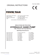
1
. INSTALL the AIR FITTINGS: Remove the thread protector from the air inlet, and install the air supply fittings
(not included) as shown. Minimum air supply must be 50 CFM and 80 PSI, with 100 PSI being the maximum.
S
ecure your pump fitting to the air supply.
IMPORTANT: Seal all external pipe connections with a high-quality, nonhardening thread sealant, such as
Power Team HTS6. PTFE tape can be used to seal hydraulic connections if only one layer of tape is used.
Apply the tape carefully, two threads back, to prevent it from being pinched by the coupler and broken off
inside the system. Any loose pieces of tape could travel through the system and obstruct the flow of oil or
cause jamming of precision-fit parts.
2. ASSEMBLE the HOSES: Clean the areas around the oil ports of the valve and hydraulic cylinders, and remove
the plastic thread protectors. Clean all hose ends, couplers, or union ends. Inspect all threads and fittings for
signs of wear or damage and replace as needed.
3. FILL the RESERVOIR: Remove the filler cap and insert a clean funnel. Fill the reservoir with hydraulic oil to
within 1/2" of the top of the filler hole. Replace the filler cap with the breather hole open.
NOTE: The pump has been shipped without oil in the reservoir. Power Team hydraulic oil has been shipped
with the pump, and if additional oil is required, use only Power Team hydraulic oil.
4. BLEED AIR from the SYSTEM: Position the hydraulic cylinder at a lower level than the pump and completely
retract any load from the cylinder. Remove the filler plug. Run the hydraulic system through several cycles of
extending and retracting the cylinder, free of any load. Check the oil level in the reservoir and add oil if needed.
PREVENTIVE MAINTENANCE
IMPORTANT:
Any repair or servicing which requires dismantling the pump should be performed in a dirt-free environment
by a qualified technician.
Disconnect the pump from the air supply before performing maintenance or repair procedures.
LUBRICATION of the AIR DRIVEN MOTOR: If the pump is operated on a continuous duty cycle or at maximum
speed for an exteded period, an automatic air line oiler is recommended. Install the oiler in the air inlet line as close
to the pumping unit as possible. Adjust the oiler to feed 1-3 drops of SAE #10 oil per minute (one drop for every 50-
75 CFM of air) into the system.
Next
Page

Operating Instructions
BLEEDING AIR from the SYSTEM: After use, air may accumulate in the hydraulic system if the reservoir level has
been permitted to get too low. This air will cause the cylinder to responded in an unstable or slow manner. To
remove this air:
A. If the pump is positioned above the cylinders:
1
. The hydraulic cylinder(s) must be positioned on their side with the couplers pointed upward.
2. Remove any load from the cylinder(s) and cycle the hydraulic system through several cycles (fully extend and
retract the cylinders).
B. If the pump is located below the cylinders:
1. Loosen cap screw on top of cylinders and start pump.
2. When oil replaces the air excaping (bleeding) from loosened screw in cylinder, stop pump and retighten the
screws.
DRAINING and FLUSHING the RESERVOIR: The reservoir should be drained, flushed, and refilled with
Power Team hydraulic oil after approximately 300 hours of use.
1. Clean the pump exterior before the pump unit is removed from the reservoir.
2. Remove the screws that hold the motor and pump assembly to the reservoir. Important: Do not damage the
gasket or bump the filter or hydraulic pressure regulating valves when lifting the pump and motor off the
reservoir.
3. After disposing of the used oil, clean the inside of the reservoir and fill with a suitable flushing oil. Rinse the filter
clean.
4. Place the pump and motor assembly back onto the reservoir and secure it with two machine screws assembled
on opposite corners of the housing.
5. Connect a hose to the advance port of the valve and place the other end of the hose into the oil filler plug hole.
6. Run the pump on "advance" for several minutes.
7. Remove the motor and pump assembly from the reservoir. Drain and clean the inside of the reservoir.
8. Fill the reservoir with Power Team hydraulic oil. Place the pump and motor assembly (with gasket) back on the
reservoir and tighten the screws securely and evenly.
HYDRAULIC FLUID LEVEL
•
Check the oil level in the reservoir after each 10 hours of use.
•
Proper oil level is within 1/2" of the filler plug when all cylinders are retracted.
ADDING OIL to the RESERVOIR
•
Use only Power Team hydraulic oil (215 SSu @ 100° F).
•
Clean the entire area around the filler plug before removing the filler plug.
•
Use a clean funnel with filter when adding oil.
•
Cylinder(s) must be fully retracted and the power supply disconnected when adding oil to the reservoir.
MAINTENANCE CLEANING
•
Keep the outer surface of the pump, all hose connections and any equipment hooked up to the pump as free of
dirt and oil as possible.
•
The breather hole in the filler cap must be kept clean and unobstructed at all times.
•
All unused couplers are to be sealed with thread protectors.
•
Change oil as recommended.
Form No. 102561
Sheet No. 2 of 4
Rev. 3 Date: 25 May 2012

Operating Instructions, Form No. 102561, Back sheet 2 of 4
Hydraulic Gauge
1. Remove the pipe plug from the gauge port.
2. Remove the four cap screws holding the valve to the pump
plate and lift the valve off the pump plate. Do NOT kink the
air lines.
3. Apply Power Team HTS6 thread sealant or PTFE tape to
the threads of the gauge. Thread the gauge into the gauge
port and tighten with a wrench.
4. Assemble the valve back onto the pump plate.
Pressure Regulating Valve
The pressure regulating valve can be adjusted to by pass oil at a desired pressure setting while the pump continues
to run.
1. Loosen the locknut on the pressure regulating valve. Turn the adjusting screw a few turns counterclockwise
(CCW) to decrease the pressure setting to a lower than desired pressure.
Note: For easy adjustment of the pressure regulating valve, always adjust the pressure by INCREASING it to
an appropriate pressure setting.
2. Connect the pump air supply and place the remote flow control valve in the advance position.
3. Slowly turn the adjusting screw in a clockwise (CW) direction to gradually increase the pressure setting. When
the desired pressure setting is reached, lock the adjusting screw in position by tightening the locknut.
TROUBLESHOOTING GUIDE
WARNING
•
To prevent injuries, any repair work or troubleshooting must be done by qualified personnel familiar
with this equipment.
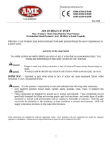
HYDRAULIC SCHEMATIC
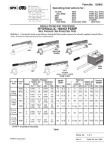
ACCESSORY INSTALLATION
Next
Page

Operating Instructions
NOTE:
•
Use the proper gauges and equipment when troubleshooting.
•
D
epending on the pump version, it is often best to check for leaks by using a hand pump and applying
pressure to the suspect area without the motor running. Watch for leaking oil and follow it back to its
source.
•
Plug the outlet ports of the pump when checking for leakage to determine if the leakage is in the pump or
if it is in the cylinder or tool.
•
Refer to Parts List #100716 or #100717 and the hydraulic schematic when using this troubleshooting
guide.
Form No. 102561
PROBLEM CAUSE SOLUTION
Pump is not delivering oil or
delivers only enough oil to
advance ram(s) partially or
erratically
(1) Oil level too low
(2) Loose fitting coupler to ram
(3) Air in system
(4) Air leak in suction line
(5) Dirt in pump or filter plugged
(6) Oil is bypassing through the
double-acting cylinder
(7) Cold oil or oil is too heavy
(Hydraulic oil is of a higher viscosity
than necessary)
(8) Relief valve or low pressure
unloading valve out of adjustment
(9) Reservoir capacity is too small
for the size of the cylinder(s) used
(10) Defective directional valve
(11) Sheared drive shaft key(s)
(12) Motor rotating in wrong
direction
(13) Vacuum in reservoir
(14) Low pressure pump worn
(1) Fill reservoir to within 1/2" of filler
plug with all cylinders retracted.
(2) Inspect couplers to insure that
they are completely coupled.
Occassionally couplers have to be
replaced because the ball-check
does not stay open due to wear.
(3) Bleed the system.
(4) Check and tighten the suction
line.
(5) Pump filter should be cleaned
and if necessary, pump should be
dismantled and all parts inspected
and cleaned.
(6) By removing the ram and
capping the hoses, the pump and
valve can be checked. Observe
whether or not the pump will hold
pressure.
(7) Change to lighter oil
(8) Readjust as needed.
(9) Use smaller cylinder(s) or larger
reservoir.
(10) Inspect all parts carefully and
replace if necessary.
(11) Replace
(12) Air line connected into wrong
port.
(13) check for plugged vent in filler
plug.
(14) Clean pump parts, replace worn
gerotor set, repair or replace the
pump housings.
Sheet No. 3 of 4
Rev. 3 Date: 25 May 2012
Next
Page

Operating Instructions, Form No. 102561, Back sheet 3 of 4
PROBLEM CAUSE SOLUTION
Pump builds pressure but cannot
maintain pressure
(1) Check to see if there are any
external leaks. If no oil leakage is
visible, the problem is internal. If
u
sing a double-acting cylinder,
remove it from the system to insure
that the leak is not in the cylinder.
(2) To test for a leaking control
valve, lift the pump from the reservoir
but keep the filter in the oil. Remove
the drain line to see if the oil is
leaking from the valve. If the valve is
not leaking, the internal check valve
could be leaking. Refer to the note
concerning checking for oil leaks at
the beginning of this Troubleshooting
Guide.
(1) Reseal leaking pipe fittings with
pipe sealant.
(2) Clean, reseat or replace control
valve parts. If the internal check
valve(s) are leaking, the pump must
be dismantled and the seat areas
repaired, poppets replaced, shear
seals relapped, etc.
Pump will not build full pressure (1) Faulty pressure gauge
(2) Check for external leakage
(3) Check the external pressure
regulator. Check the relief valve
setting.
(4) Look for internal leakage in
double-acting cylinders.
(5) Check for leaks in the flow
control valve
(6) Inspect the pump for internal
leakage. Check high pressure pump
inlet or outlet ball checks.
(7) Sheared Key(s)
(8) Inadequate air pressure
(1) Calibrate gauge
(2) Seal any faulty pipe fitting with
pipe sealant.
(3) Lift the pump from the reservoir
but keep the filter immersed in oil.
Note the pressure reading when the
relief valve begins to open up. If
functioning normally, it should start to
leak off at relief valve pressure.
(4) Remove the cylinder from the
pump. If the pump builds full
pressure, the cylinder is defective.
(5) Clean and reseat or replace
parts.
(6) Same procedure as above but
look for leaks around the entire inner
mechanism. If there are no visible
leaks the high pressure pump
subassembly may be leaking.
Remove all parts. Check the valve
head assembly body for any damage
to the seat area. Clean and reseat if
necessary. Inspct for damage and
replace parts if necessary, then
reassemble.
(7) Replace
(8) Increase air pressure.
Next
Page

Operations Instructions
Form No. 102561
PROBLEM CAUSE SOLUTION
Cylinder(s) will not retract (1) Check the system pressure; if
t
he pressure is zero, the control
valve is releasing pressure and the
p
roblem may be in the cylinders,
(mechanical linkage connected to
cylinders), or quick-disconnect
couplings.
(2) Defective valve
(3) Inadequate air pressure
(1) Check the cylinders for broken
r
eturn springs and check couplers to
insure that they are completely
c
oupled. Occasionally couplers have
to be replaced because one check
does not stay open in the coupled
position.
(2) Check valve operation and
instpect parts. Replace if necessary.
(3) Increase air pressure.
Pump delivers excess oil pressure (1) Check pressure gauge
(2) Relief valve not properly set
(1) Calibrate gauge
(2) Reseat the relief valve
Sheet No. 4 of 4
Rev. 3 Date: 25 May 2012
1/7