Samsung NC190 User manual

Category
LED displays
Type
User manual

This manual is also suitable for

SyncMaster NC190,NC240
LCD MONITOR
quick start guide
1 Installing the Product
1-1 Package Contents
Unpack the product and check if all of the following contents have been included.
Store the packaging box in case you need to move the Product at a later stage.
Monitor
1-2 Installing the Stand
Before assembling the product, place the product down on a flat and stable surface so that the screen is facing downwards.
CONTENTS
Installation Manual Product Warranty User Manual Power Cord
OPTIONAL PARTS
Keyboard (USB) Mouse (USB) D-Sub Cable
Place a soft cloth over the table to protect the product and place the product onto the
cloth so that the front of the product is facing downwards.
Do not remove the stopper pin before installing the base.
Hold the main body of the product with your hand as shown by the figure.
Insert the stand base into the stand connection part in the direction shown in the figure.
Turn the connecting screw at the bottom of the stand fully so that it is completely fixed.
Installing the Product 1-3
Disassembly is in the reverse order of assembly.
1-3 Installing a Wall Mount
Before installation, disassemble the product according to the following steps.
After the installation of the base, stand the monitor up as shown in the figure. Now you
can remove the stopper pin to adjust the stand.
- Caution
Avoid lifting the product holding only the stand.
1-3 Installing the Product
This product provides a wall mount of 100 mm x 100 mm(200 mm x 100 mm) that complies with the VESA specifications.
1. Turn the product off and unplug the power cord from the wall outlet.
2. Place a soft cloth or cushion on a flat surface to protect the panel and place the product face down.
3. Separate the stand.
4. Align the groove of the Monitor's wall mount base with the groove in the wall mount ki and firmly fix the wall mount kit by
fastening the screws.
Lift up the monitor stand to the maximum angle with your left hand, and remove the back
decoration cover with your right hand, as shown in the figure.
Remove the two screws(A).
Remove the stand arm in the direction shown in the figure.
100 mm x 100 mm 200 mm x 100 mm
A. Wall Mount Base
B. Wall Mount Kit (Optional)
Installing the Product 1-4
•If you use a screw that is longer than the standard specifications, the inside of the product may be damaged.
•For wall mounts that are not compatible with the standard VESA specifications, the length of the screw may differ depending
on the corresponding specifications.
•Do not use screws that are incompatible with the standard VESA specifications and do not assemble them using excessive
force.
This may result in damage to the product or injury due to the product falling. Samsung shall not be held liable for any damage
or injury.
•Samsung shall not be held liable for any damage to the product or injury caused by using a stand that is not compatible with
the specified specifications or due to an installation not performed by an authorized installation engineer.
•When installing the product using a wall mount, purchase a wall mount that provides at least 4 inches (10 cm) of space from
the wall.
•Samsung shall not be held liable for any problems caused by using a stand that is not compatible with the specified
specifications.
•Use a wall mount according to specifications of your country.
1-4 Connecting to your Network
The connecting part may differ depending on the product model.
Connect between the [LAN] port on the product and your network using a LAN cable.
The two [LAN] ports are designed to work as an Internet HUB. One port can be used for input and the other port for output
to connect the product to an external Internet device. Both ports can be used for either input or output.
1-5 Installing the Product
1-5 Connecting Power
Connect one end of the power cord to the POWER port of the product and connect the other end of the power cord to a 220V or
110V wall outlet.
(The input voltage is switched automatically.)
Installing the Product 1-6
1-6 Connecting to another Monitor
Please select the right connection method for your monitor.
When using the [RGB OUT] port
Connect between the [RGB OUT] port on the product and the D-Sub port on your monitor using a D-Sub cable.
When using the [DVI OUT] port
Connect between the [DVI OUT] port on the product and the DVI port on your monitor using a DVI cable.
Connect to the [DVI OUT], [RGB OUT] port to display the same picture on another monitor such as the projector.
(For presentation purposes)
1-7 Installing the Product
1-7 Connecting with a PC
Connect the [RGB IN] port of the product to the [D-Sub] port of your PC with a D-Sub cable.
Use the [RGB IN] port to directly connect the monitor to a PC.
Installing the Product 1-8
1-8 Connecting a Stereo Cable
Connect the [AUDIO IN] port on the rear side of the monitor to the sound card of the PC.
1-9 Installing the Product
1-9 Connecting USB
The USB port of the monitor supports High-Speed Certified USB 1.1.
Connect USB devices such as a mouse, keyboard and external storage devices (DSC (Digital Still Camera), MP3, external
storage, etc.).
You can use a USB device such as a mouse, keyboard, Memory Stick, or external hard disk drive by connecting them to the
USB port of the monitor without connecting them to the PC.
Installing the Product 1-10
1-10 Connecting Headphones
Connect your headphones to the Headphone connection terminal.
You may connect your headphones to the monitor.
1-11 Installing the Product
1-11 Connecting MIC
Connect the microphone cable to the MIC port on the monitor.
You may connect your microphone to the monitor.
Installing the Product 1-12
1-12 Kensington Lock
A Kensington Lock is an anti-theft device that enables users to lock the product so that they can safely use it in public locations.
Since the shape and usage of the locking device may differ depending on the model and the manufacturer, for more information,
refer to the User Manual supplied with the locking device. You have to purchase an additional locking device.
Locking the product
1. Insert the locking part of the locking device into the hole of the Kensington lock of the product ( ) and turn it in the locking
direction ( ).
2. Connect the Kensington lock cable.
3. Tie the Kensington lock cable to a desk or heavy object.
You can purchase the locking device from an electronics store or an online shop.
1-13 Product Operating Buttons
Product Operating Buttons
The buttons are located on the bottom of the product.
1-13 Installing the Product
Icon Description
MENU/
Press this button to view the On Screen Display (OSD).
This button is also used to exit the OSD or to return to a higher-level OSD menu
* OSD Adjustment Lock
This function locks the OSD in order to maintain the current settings or to prevent the settings
from being changed by another person
On: If you press and hold the MENU button down for 5 seconds, the OSD Adjustment Lock
function is activated.
Off: If you press and hold the MENU button down for 5 seconds again, the OSD Adjustment
Lock function is disabled.
Even if the OSD Adjustment Lock is on, <Brightness>, <Contrast> and <MagicBright>
can be modified.
This button performs the role of the Power button for the server PC in Client mode and per-
forms the role of the direction buttons in Analog mode.
When OSD is not on the screen, push the button to adjust volume.
/ Adjust items in the menu.
/SOURCE
Use this button to select a function
Press [ /SOURCE] to select the video signal from a connected device while the OSD is
off. (When the [ /SOURCE] button is pressed to change the input mode, a message
appears in the upper left of the screen displaying the current mode).
AUTO /
In <Analog> mode, this button is used for auto adjustments. In <Client> mode, it is used to
disconnect from the server.
Press this button to turn the product on or off
Troubleshooting 2-1
2 Troubleshooting
2-1 Monitor Self-Diagnosis
You can check if the product is working properly using the Self-Diagnosis function.
If a blank screen is displayed and the Power LED blinks even if the product and the PC are properly connected, perform
the self-diagnosis function according to the procedures below.
1. Turn the product and the PC off.
2. Separate the signal cable from the product .
3. Turn the product on.
4. If the product is working properly, the <Check Signal Cable> message appears.
In this case, if a blank screen is displayed again, make sure that there is no problem with the PC and the connection. The product
is working properly.
2-2 Before Requesting Service
Please check the following before requesting After-Sales service. If the problem continues, please contact your nearest
Samsung Electronics Service Center.
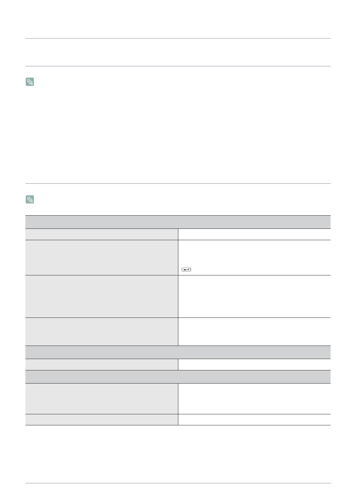
A blank screen appears / I cannot turn the product on
Is the power cord connected properly? Check the connection status of the power cord.
Is the <Check Signal Cable> message displayed on the
screen?
Check the cable connecting the PC and the product.
If the message appears on the screen even if the cable is
properly connected, recheck the input signal by pressing the
/SOURCE button of the product.
Is the <Not Optimum Mode> message displayed on the
screen?
This occurs when the signal from the graphics card exceeds
the maximum resolution or the maximum frequency of the
product.
In this case, set up the appropriate resolution and the fre-
quency for the product.
Is a blank screen displayed and does the power LED blink at
a 1 second interval?
This occurs when the power saving function is running.
If you click the mouse or press any key, the screen will be
turned on.
The on screen adjustment menu (OSD) does not appear.
Did you cancel the screen adjustment? Check if the <OSD Adjustment Lock> function is set to Off.
The color is weird / The picture is displayed in black and white
Is the entire screen displayed in the same color as if viewing
the screen through a cellophane paper?
Check the cable connection to the computer.
Reinsert the graphics card into the computer completely.
Check if the <Color Effect> is set to <Off>.
Is the graphics card configured correctly? Set up the graphics card referring to the user manual.
2-2 Troubleshooting
The display area suddenly moves to an edge or to the center.
Did you change the graphics card or the driver? Please press the [AUTO] button to run the auto adjustment
function.
Did you change the resolution and frequency appropriate to
the product?
Set the resolution and the frequency to the appropriate values
in the graphics card
Refer to the (Standard Signal Mode Table)
Is the graphics card configured correctly? Set up the graphics card referring to the user manual.
The pictures are out-of-focus.
Did you change the resolution and the frequency appropriate
to the product?
Set the resolution and the frequency to the appropriate values
in the graphics card
Refer to the (Standard Signal Mode Table)
The color is displayed in 16 bit (16 colors). The color has been changed after changing the graphics card.
Did you install the device driver for the product? Windows ME/XP/2000 : Set the color again by selecting Con-
trol Panel Display Settings.
Is the graphics card configured correctly? Configure the color again in accordance with the new graph-
ics card driver.
When I connect the monitor, the 'Unknown monitor, Plug&Play (VESA DDC) monitor found' message is displayed.
Did you install the device driver for the product? Install the device driver referring to the descriptions about the
driver installation.
Check if all the Plug&Play (VESA DDC) functions are sup-
ported referring to the User Manual of the graphics card.
Install the device driver referring to the descriptions about the
driver installation.
A “beep, beep” sound is heard when booting the computer.
If the beep sound is generated 3 or more times when booting up the computer, please request service for the computer.
Problems related to Audio
No sound Ensure that the audio cable is firmly connected to both the
audio-in port on your monitor and the audio-out port on your
sound card.
Check the volume level.
Sound level is too low. Check the volume level.
If the volume is still too low after turning the control to its max-
imum, check the volume control on the computer sound card
or software program.
Troubleshooting 2-3
2-3 FAQ
FAQ! Please try the following!
How can I change the frequency of the video signal? You have to change the frequency of the graphics card.
(For more information, refer to the User Manual of the com-
puter or the graphics card.)
How can I change the resolution? Windows XP : Change the resolution by selecting Control
Panel
Appearance and Themes Display Settings.
Windows ME/2000 : Change the resolution by selecting Con-
trol Panel
Display Settings.
(For more information, refer to the User Manual of the com-
puter or the graphics card.)
How can I use the power saving function?
Windows XP : Configure it by selecting Control Panel
Appearance and Themes
Display Screen Saver Set-
ting or configure it in the BIOS Setup of the computer.
Windows ME/2000 : Configure it by selecting Control Panel
Display Screen Saver Setting or Configure it in the
BIOS Setup of the computer.
For more information, refer to the Windows user manual for
the computer.
2-3 Troubleshooting
  • Page 1 1
  • Page 2 2
  • Page 3 3
  • Page 4 4
  • Page 5 5
  • Page 6 6
  • Page 7 7
  • Page 8 8
  • Page 9 9
  • Page 10 10
  • Page 11 11
  • Page 12 12
  • Page 13 13
  • Page 14 14
  • Page 15 15
  • Page 16 16
  • Page 17 17
  • Page 18 18
  • Page 19 19

Samsung NC190 User manual

Category
LED displays
Type
User manual
This manual is also suitable for

Ask a question and I''ll find the answer in the document

Finding information in a document is now easier with AI