Page is loading ...

Owners Manual Version 1.1a
Models
M1512
M1512E
M1524
M1524E
Trace Engineering Company, Inc.
5916 195th NE
Arlington, Washington USA 98226
Phone (360) 435-8826
Fax (360) 435-2229
http://www.traceengineering.com
Part #830-1

This page intentionally left blank

Packaging Materials
Thank you for choosing Trace Engineering products to meet your alterna-
tive-energy power needs. We make every effort to ensure that your in-
verter/charger packaging includes the following materials:
Owner's Manual;
Red\Black battery terminal covers (with hardware);
Trace bumper sticker;
If any of the above listed materials are missing from your package, or if it is un-
satisfactory in any manner, please call Customer Service at (360) 435-8826 or
fax this page with your comments to (360) 435-2229.
Model Number: _____________________________________
Serial Number: _____________________________________
Purchase Date: _____________________________________
Comments:
________________________________________________________________
________________________________________________________________
________________________________________________________________
________________________________________________________________
________________________________________________________________
________________________________________________________________
Thank you for choosing Trace Engineering to meet your independent power
needs. Check out our web site at www.traceengineering.com for more informa-
tion and answers to your FAQ's.

Table Of Contents
UL Safety Instructions
General Precautions................1
Personal Precautions ...............4
Product Overview
..........................5
Inverter Operation
Self Test .........................6
Front Panel Controls and LED Indicators ........6
Front Panel ....................6
Power / Charger Only Switch ...........7
On / Search LED .................7
Error Indicators ..................7
Circuit Board Controls ..................8
Search Watts ...................9
Bat Size A/H ...................10
LBCO/XFR ....................10
Waveform .......................11
Regulation .......................11
Battery Charger
Theory of Operation ..................12
Inverter to Charger Transition ..........12
Transfer Switching Speed ............12
Battery Terminology ...............12
Charger Terminology ..............13
Three Stage Battery Charging ..........13
Battery Charger Controls and LED Indicators .....14
Bulk Charge LED.................14
Float Charge LED ................15
Adjusting Charger Rate .............15
AC Amps In ...................15
Circuit Board Fuses ...............15
Temperature Compensation ...........15

Selecting Battery Types .............16
Generator Requirements.............16
Batteries
Sizing .........................17
Estimating Battery Requirements............17
Hookup Configurations.................20
Installation
Environment ......................19
AC Wiring
Overview .....................20
Shore Power Connections to Boats Main AC Panel20
Galvanic Corrosion and Electrolysis .......21
Connection of Shipboard Sources of AC Power . 21
AC Connections .................23
Important Precautions ..............24
Ground Fault Interrupters ............24
AC Wiring Diagram ...............25
DC Wiring
Safety Instructions ................26
DC Disconnect ..................26
Battery Cable Connection ............26
Battery Cable Sizing ...............27
Installation Diagrams
A. Installation with Single AC Panel .......28
B. Installation with AC Sub Panel ........29
C. Installation with External Relay ........30
D. Installation with External Relay ........31
E. Installation with External Relay ........32
Troubleshooting Guide
............................33
Applications
Resistive Loads .................34
Inductive Loads.................34
Problem Loads .................35

Technical Information
Specifications .....................37
Performance Graphs
Load Capacity vs. Time .............38
Power vs. Efficiency ...............39
Battery Charge Rate vs. Peak Input Voltage...40
Tables
Table 2- Battery Drain vs. Loads (M1512) ....41
Table 4- Battery Drain vs. Loads (M1524) ....42
Table 5 - Metric to English Wire Size ......43
Other Products
..........................44
Warranty Information
Limited Warranty ..................i
Warranty Procedure ................ii

IMPORTANT SAFETY INSTRUCTIONS
SAVE THESE INSTRUCTIONS
This manual contains important safety and operating instructions as prescribed
by ANSI/UL specifications for inverters used in marine and RV applications.
This manual covers inverter/charger models: M1512 and M1524.
These models are ETL listed to UL1236, UL458 and meets ABYC standards for
marine use. Both are listed to UL458 for RV/Motor home use.
General Precautions
1. Before using the charger/inverter, read all instructions and cautionary mark-
ings on (1) the charger/inverter and (2) the batteries.
2. CAUTION- To reduce risk of injury, charge only deep cycle lead acid, lead
antimony, lead calcium and gel cell type rechargeable batteries. Other types
of batteries may burst causing personal injury and damage. Do not use bat-
tery charger for charging dry-cell batteries that are commonly used with
household appliances. These batteries may burst and cause injury to per-
sons and damage property.
3. Do not expose charger/inverter to rain, snow or moisture.
4. Use of an attachment not recommended or sold by TRACE ENGINEER-
ING may result in a risk of fire, electric shock, or injury to persons.
5. Make sure wiring is located so that it will not be stepped on, tripped over,
or otherwise subjected to damage or stress.
6. Do not operate the charger/inverter with bad wiring - replace immediately.
7. Do not operate charger/inverter if it has received a sharp blow, been
dropped, or otherwise damaged in any way. Take it to a qualified service
center for inspection and test.
8. Do not disassemble the charger/inverter; take it to a qualified service center
when service or repair is required. Incorrect re-assembly may result in a risk
of electric shock or fire.
9. To reduce risk of electric shock, disconnect all wiring before attempting
any maintenance or cleaning. Turning off controls will not reduce this risk.
Page 1

10. WARNING - WORKING IN VICINITY OF A LEAD ACID BATTERY IS
DANGEROUS. BATTERIES GENERATE EXPLOSIVE GASES DUR-
ING NORMAL OPERATION.
11. NEVER charge a frozen battery.
12. If necessary to remove battery from vehicle to charge, always remove
grounded terminal first. Make sure all accessories in the vehicle are off, so
as not to cause an arc.
13. Be sure area around battery is well ventilated while battery is being
charged. Gas can be forcefully blown away by using a piece of cardboard
or other nonmetallic material as a fan.
14. Clean battery terminals. Do not allow corrosion to come in contact with
eyes.
15. Add distilled water in each cell until battery acid reaches level specified by
battery manufacturer. This helps purge excessive gas from cells. Do not
over-fill. For a battery without cell caps, carefully follow manufacturer’s
recharging instructions.
16. Study all battery manufacturer’s specific precautions such as removing cell
caps while recharging and recommended rates of charge.
17. FOLLOW THESE STEPS WHEN BATTERY IS OUTSIDE VEHICLE. A
SPARK NEAR THE BATTERY MAY CAUSE BATTERY EXPLOSION.
TO REDUCE RISK OF ASPARK NEAR BATTERY:
A. Check polarity of battery posts. POSITIVE (POS,P,+) battery post usu-
ally has a larger diameter than NEGATIVE (NEG,N,-) post.
B. Attach an insulated battery cable at least 24 in. long to the NEGATIVE
(NEG,N,-) post. Size in accordance with chart on pg. 27.
C. Connect POSITIVE (RED) charger battery cable terminal to the POSI-
TIVE (POS,P,+) post of battery.
D. Position yourself at the free end of cable as far away from battery as
possible, then connect NEGATIVE (BLACK) charger battery cable to
the charger.
E. Do not face battery when making final connection.
F. When disconnecting charger, always do so in reverse sequence of con-
necting procedure, and break first connection while as far away from
battery as practical.
Page 2

18. EXTERNAL CONNECTIONS TO CHARGER SHALL COMPLY WITH
THE UNITED STATES COAST GUARD ELECTRICAL REGULATIONS
(33CFR1833, SUB PART 1).
19. No terminals or lugs are required for hook-up of the AC wiring. AC wiring
should be 12 (AWG) gauge 90 degree C copper wire. Units supplied with
the optional STANDBY feature should use 8 (AWG) gauge 90 degree C
copper wire. Battery cables must be rated for 105 degree C and should be
2/0 (AWG) gauge (welding cable). A crimped and soldered lug with a 5/16
hole attached to the battery cable is required for connection to the
inverter/charger.
20. Torque all AC wiring connections to 20 inch pounds. Torque all DC cable
connections to 12 foot pounds.
21. Symbols used in this manual and on the inverter/charger are:
22. Tools required to make AC wiring connections: Wire strippers 1/2",
(13MM) open end wrench or socket, Philips screw driver #2, Slotted screw
driver 1/4" (6MM) blade.
23. This inverter/charger is intended to be used with a battery supply of nomi-
nal voltage that matches the last two digits of the inverter model number,
e.g.. 12 volt with a M1512.
24. Instructions for wall or ceiling mounting: See mounting instruction section
of this manual. For battery installation and maintenance: read the manufac-
turer’s installation and maintenance instructions prior to operating.
25. No AC or DC disconnect switch is provided as an integral part of this unit.
Both AC and DC disconnects must be provided as part of the system instal-
lation. See SYSTEM SAFETY WIRING REQUIREMENTS section of this
manual.
26. No over current protection for the battery supply is provided as an integral
part of this unit. Over current protection of the battery cables must be pro-
vided as part of the system installation. See SYSTEM SAFETY WIRING
REQUIREMENTS section of this manual.
Page 3
Chassis AC Output
AC Input Phase

27. No over current protection for the AC output wiring is provided as an inte-
gral part of this unit. Over current protection of the AC output wiring must
be provided as part of the system installation. See SYSTEM SAFETY
WIRING REQUIREMENTS section of this manual.
28. GROUNDING INSTRUCTIONS - This battery charger should be con-
nected to a grounded , metal, permanent wiring system; or an equipment
-grounding conductor should be run with circuit conductors and connected
to equipment-grounding terminal or lead on battery charger. Connections to
battery charger should comply with all local codes and ordinances.
PERSONAL PRECAUTIONS
1. Someone should be within range of your voice or close enough to come to
your aid when you work near lead-acid batteries.
2. Have plenty of fresh water and soap nearby in case battery acid contacts
skin, clothing, or eyes.
3. Wear complete eye protection and clothing protection. avoid touching eyes
while working near batteries.
4. If battery acid contacts skin or clothing, wash immediately with soap and
water. If acid enters eye, immediately flood eye with running cold water for
at least 10 minutes and get medical attention immediately.
5. NEVER smoke or allow a spark or flame in vicinity of battery or engine.
6. Be extra cautious to reduce the risk of dropping a metal tool onto batteries.
It might spark or short-circuit batteries or other electrical parts that may
cause an explosion.
7. Remove personal metal items such as rings, bracelets, necklaces, and
watches when working with a lead-acid battery. A lead-acid battery can
produce a short-circuit current high enough to weld a ring or the like to
metal, causing a severe burn.
Page 4

Product Overview
The Model M1512, M1524 and the 230 vac “E” versions are microprocessor
controlled power inverter’s with built-in battery chargers and automatic transfer
circuitry. The inverter is a modified square wave design tailored to the require-
ments of the boating and RV users. Tight voltage and frequency regulation, sub-
stantial surge power, high efficiency and comprehensive protection circuitry
characterize the design.
The battery charger uses a three stage charging technique that ensures rapid
charging without battery gassing. Transferring to and from battery charging
mode is done automatically. When shore power is present the unit charges bat-
teries and passes the shore power thru to its AC output. If shore power fails the
unit returns to inverter operation. Transfer time is typically fast enough to sup-
port computers.
Additionally, many advance features are standard.
• Adjustable energy saving Search Mode.
• Current compensated protection against battery over-discharge.
• Adjustable transfer voltage.
• Adjustable charge rate.
• Charger only operation so that power failure will not deplete the
batteries.
• Adjustable automatic charge rate reduction to limit AC input current.
• LED volt and amp meters. Amp meters measure charge rate and
inverter consumption.
• Automatic return to operation after most error conditions.
• Synchronous rectification battery charger topology for cooler
operation.
• Selectable Gel or liquid electrolyte battery charger settings.
• Temperature compensated charger with sensor.
• Automatic return to operation after low battery condition with the
resumption of AC power.
We at Trace Engineering sincerely thank you for choosing our products and trust
that you will be completely satisfied with them.
Page 5

Inverter Operation
Self Test
When first connected to batteries, the inverter initiates a self test. The cooling
fan runs momentarily and the internal speaker chirps. During this time the Bulk
Charge, Float Charge and On / Search LED’s light. This is followed by the
Volts and Amps LED’s meters lighting sequentially from the bottom to the top.
Once this is completed, the unit is ready to be turned on with the Power /
Charger Only switch.
Front Panel Controls and LED Indicators
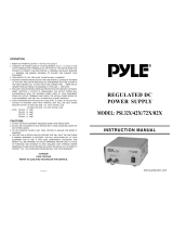
Front Panel
Shown below are the M1512’s front panel controls and indicator lights . The
Model M1524’s are similar with only the voltage and amperage values changed.
The LED’s provide information about the unit when it is in either its inverter or
battery charging mode of operation.
Page 6
Figure 1, Front Panel Controls

Power / Charger Only Switch
The Power / Charger Only control is a momentary rocker switch. Momentary
switches do not remain depressed after use. It is used to turn the inverter/charger
mode on and off. Its also, used to turn the charger only mode on and off. When
the unit is first connected to batteries it executes a self test. Upon completion the
unit is off.
Turning on to Inverter/charger mode
If the inverter is off - press the momentary switch to the POWER position.
Turning on to Charger Only mode
If the inverter is off - press the momentary switch to the CHARGER ONLY
position.
This position allows the unit to operate as a battery charger only. Power is
passed thru the unit from AC input to AC output. However, if power fails the
unit will not invert and deliver power to its AC output.
Turning the unit off
If the unit is in inverter/charger mode - press Power. If the unit is in Charger
Only mode - press Charger Only. In order to change from inverter/charger
mode to charger only mode or vice versa the unit must first be turned off.
On / Search LED
This green LED indicator lights when the unit is in the inverter mode (not charg-
ing batteries). When the inverter is in its search mode the LED will blink. While
the inverter is delivering full output voltage the LED is on solid.
Error Indicators
The top four LED’s of the vertical row of LED’s that comprise the AMPS meter
are used to indicate error conditions. The appropriate LED will flash if a condi-
tion unsafe for inverter or charger operation exits. Additionally, the On / Search
LED will blink and the buzzer will beep. The volt meter continues to operate un-
der error conditions.
• High Bat- High battery voltage turns the unit off immediately. When
battery voltage falls to a safe level, the inverter returns automatically to
operation.
• Over Temp- The unit monitors the temperature of its transformer and
power devices. The Over Temp is activated if either approach their
design limits. A ten second warning is provided before shutdown. After
the temperatures fall the inverter returns automatically to operation.
• Overload- Overload occurs when the inverter is asked to deliver too
much power or the output is short circuited. Overload protection is
Page 7

instantaneous. If the over-current condition lasts for less than 10
seconds the unit will automatically resume operation. It will have to be
manually restarted if it is a prolonged overload that lasts longer than 10
seconds.
• Low Bat- When a low battery condition occurs the unit provides a ten
second warning before interrupting operation. Once the unit has turned
itself off to protect the batteries, it will return to operation when either
AC is available at its input terminals or it is manually restarted.
Note:The battery charger control circuit operates from battery voltage.
If battery voltage falls below 7 volts neither the charger nor inverter
will operate. In this situation, a small charge from a stand-alone charger
will be required to bring the battery to a high enough voltage for the
inverter/charger to resume operation.
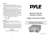
Circuit Board Controls
Shown below are the M1512’s circuit board controls, jumpers, accessory jacks
and low battery alarm terminals. These are accessed by opening the front panel
door. The door is opened by removing the four Phillips-head screws that secure
it. The circuit board is attached to the back side of the door. The first three con-
trols on the upper left hand corner are used to adjust inverter features. The re-
maining two are used for battery charging and are discussed in that section of
the manual.
Page 8
Figure 2, Circuit Board Controls

Search Watts
The SEARCH WATTS control is used for adjusting the sensitivity of the
search mode circuit.
The M1512 and M1524 inverters feature an adjustable search mode circuit. It
minimizes power drain by reducing the inverter’s output to small test pulses
when there is no load turned on. These pulses are used to detect the presence of
a load. When a load is detected the inverters’s output goes to full voltage. The
sensitivity of the detection threshold is adjustable. Turning the SEARCH
WATTS control clockwise decreases the sensitivity (bigger loads are required
for the inverter to return to normal operation). Turning the control full counter-
clockwise defeats the search mode feature.
Example: With the SEARCH WATTS control set to detect a 40 watt load, a 50
watt load will bring the unit to full output voltage, however a 30 watt load will
leave the inverter in its energy saving search mode state. If the sensitivity is in-
creased by setting the control to 10, a 20 watt load will bring the inverter out of
the search mode, while a 5 watt load will not.
When in the search mode, the green On / Search LED will blink and the
inverter will make a ticking sound. At full output voltage, the On / Search LED
will burn steadily and the inverter will make a steady humming sound. When
the inverter is used as an uninterruptable power supply the search mode function
should be defeated.
A neon
nightlite can also be used as a good indicator to determine if the inverter
is in search mode. Simply plug the light into any AC outlet. When the inverter
is in the search mode the light will blink. If the inverter is running a load, the
light will be solid.
Exceptions: (Murphy’s Law) Unfortunately, things don’t always work the
way the manual says they will.
Example A: If the SEARCH WATTS control is set to detect a 40 watt load and
a 30 watt incandescent light is turned on, the inverter will detect the light. The
light is a bigger load than 40 watts when its filaments are cold. When the light
gets bright the filaments heat up and the light becomes a 30 watt load. Since this
is below the control setting of 40, the inverter will not detect it and the light will
go out. And so on and so forth.
Example B: If the SEARCH WATTS control is set to detect a 30 watt load and
a 40 watt florescent light is turned on, the inverter will not detect the light. The
light presents a smaller load than 30 watts until the gas in the florescent tube
ionizes,
Example C: There are some appliances that draw power even though they are
turned off. TV’s with instant on circuits, microwave ovens with digital displays
and VCR’s are examples. These loads present a dilemma. If the sensitivity is
set higher than the combination of these loads, then an auxiliary load must be
used to bring the inverter out of the search mode before the appliances can be
turned on. If the sensitivity is set lower
than this combination of loads, the loads
will be left on and will put an additional drain on the batteries. (Three such 15
watt loads would amount to an additional 90 amp/hours per 24 hours in a 12
Page 9

VDC system.) One solution is to turn these items off at the outlet. Use an exten-
sion cord with a rocker switch, a switch at the outlet or the appropriate circuit
breaker.
BAT SIZE A/H
The BAT SIZE A/H control is used to inform the inverter’s microprocessor of
the battery bank size. This allows the inverter to make better “over-discharge
protection” and battery charging decisions. Battery bank size is adjustable from
50 to 1000 amp hrs.
LBCO/XFR
This cryptic and tricky control provides two different functions. When the dial is
set to the left side the LBCO feature is disabled. When the dial is set to the right
side the LBCO feature is enabled. Transfer voltage (the XFR part) is the other
feature controlled by this dial. With the dial set to either the left or right side,
transfer voltage can be adjusted from 80 to 105 VAC (on 230 VAC models 155
to 200 VAC).
LBCO (Low Battery Cut-out)
The LBCO feature provides battery over-discharge protection. This circuit is
unique to Trace Inverters. It monitors both the current being drawn by the
inverter and the battery voltage. Battery voltage alone is not an accurate indica-
tor of battery condition. The internal resistance of a battery causes its output
voltage to drop when the battery is delivering current. The smaller the battery
the greater the voltage drop for a given load. This battery voltage drop due to
load is not an indicator of the battery’s state of charge. The Trace “load com-
pensated” circuit uses information about the battery bank size, temperature and
the load current to derive a corrected battery voltage. If the circuit determines
that the battery condition is low, the inverter turns off and will reset when AC
power is input to the inverter or the unit is manually restarted.
If control is set between 7:00 and 11:00 o’clock the LBCO feature is disabled.
When set between 1:00 and 5:00 o’clock the LBCO feature is enabled. If the
over discharge circuit is defeated the inverter itself is protected from low battery
voltage conditions by an additional protection circuit.
Turnoff voltage is compensated to 1.83 v per cell.
Page 10

Transfer Voltage
When shore power fails or falls to a low level, the unit changes from battery
charger mode to inverter mode. The shore power voltage point at which the
inverter decides to change modes is called the transfer voltage. It is adjustable
from 80 to 105 VAC. The adjustment is made by rotating the dial between 7:00
and 11:00 o’clock if the LBCO is defeated. The adjustment is made by rotating
the dial between 1:00 and 5:00 o’clock if the LBCO is enabled.
Higher voltage setting result in slightly faster transfer times. Lower settings are
less likely to cause a transfer due to voltage fluctuations.
Waveform
The output waveform
of the inverter is re-
ferred to as a modi-
fied sine wave. This
waveform is suitable
for a wide variety of
applications. Induc-
tion motors (i.e. re-
frigerators, drill
presses), resistive
loads (i.e. heaters,
toasters), universal
motors (i.e. hand
tools, vacuum clean-
ers) as well as micro-
wave ovens and
computers are all
suitable loads.
The waveform could be more accurately described as a pulse width modified
square wave. The accompanying Figure 2 shows the relationships between
square wave, sine wave and modified sine wave formats.
Regulation
The inverter is RMS voltage regulated. RMS regulation ensures that resistive
loads will always have the same amount of power delivered to them as battery
voltage changes. Regulation is achieved by varying the width of each pulse.
Peak voltage is the product of the battery voltage times the turns ratio of the
inverter’s power transformer and is therefore not regulated.
Page 11
Figure 3, Modified Sine Wave

Battery Charger
Theory of Operation
Inverter to Charger Transition
The internal battery charger and automatic transfer relay allows the unit to oper-
ate as either a battery charger or inverter (but not both at the same time). An ex-
ternal source of AC power (e.g., shore power or generator) must be supplied to
the inverter’s AC input in order to allow it to operate as a battery charger. When
the unit is operating as a charger, it’s AC output is powered by the external
source (i.e. generator or shore power).
The inverter automatically becomes a battery charger whenever AC power is de-
livered to its AC inputs. There is a 40 second time delay from the time the
inverter senses that AC is present at its input to when the transfer is made. This
delay is built in to provide time for a generator to spin-up to a stable voltage and
avoid relay chattering. While in the battery charger mode the inverter’s AC in-
put is internally connected to the inverter’s AC output. The maximum power
that can be handled by the inverter’s internal wiring and transfer relay is 30
amps. During heavy charging a maximum of 12 amps is consumed by the
charger. If the total current required by the loads and the charger exceeds 30
amps, the charger will automatically reduce its charge rate to maintain the 30
amp limit.
Models with 230 VAC output have a 20 amp maximum thru-put current. The
charger draws a maximum of 6 amps.
Transfer Switching Speed
While this inverter is not designed specifically as an uninterruptable power sup-
ply (UPS) system, its transfer time is normally fast enough to hold up comput-
ers. The transfer time is a maximum of 16 milliseconds.
When switching from inverter to charger, the inverter waits approximately 40
seconds to ensure the AC source is stable (generator up to speed).
PC Magazine has run tests that indicated a transfer time of 100 milliseconds will
normally hold up the present generation of PC’s.
Battery Terminology
A description of the battery charger operation requires the use of terms with
which you may not be familiar. The following terms will be referred to in the
description of the battery charger operation.
Page 12

• Electrolyte- Typically a mixture of water and sulfuric acid, it is
commonly referred to as battery acid.
• Plates- Originally made of lead, they are now made of lead oxide.
Plates are the part of the battery that collects current and are connected
to the terminals. There are several plates in each cell, each insulated
from the other by separators.
• Sulfating- As a battery discharges, its plates are progressively covered
with lead sulfate. During recharging, the lead sulfate is removed from
the plates and recombines with the electrolyte. If the lead sulfate
remains on the plates for an extended period of time (over two months),
it hardens, and recharging will not remove it. This reduces effective
plate area and the battery capacity is diminished.
• Stratification- Over time the batteries’ electrolyte (liquid) tends to
separate. The electrolyte at the top of the battery becomes watery while
at the bottom it becomes more acidic. This effect is corrosive to the
plates.
• Deep Cycle- A deep cycle occurs when a battery has been discharged
such that less than 20% of its capacity remains (80% discharge).
• Temperature Compensation- The optimum voltage is temperature
dependent. As temperature decreases the proper voltage for each
charge stage needs to be increased. The temperature probe will
automatically re-scale charge voltage settings for ambient temperature.
The compensation slope based on cell voltage is -2.17 mv per degree F.
per cell.
Charger Terminology
• Bulk Voltage- This is the maximum voltage at which the batteries will
be charged during a normal charging cycle. The normal range is 2.367
to 2.4 volts per cell. For a 12 VDC battery (6 cells) this is 14.2 to 14.4.
Liquid electrolyte batteries are usually set to the higher voltage, while
gel cell batteries are set to the lower.
• Float Voltage- This is the voltage at which the batteries will be
maintained after they have been charged. A range of 13.2 - 13.4 is
appropriate for most sealed and non-sealed batteries.
• Absorption Stage- During this part of the charge cycle, the batteries are
held at the bulk voltage and accept whatever current is required to
maintain this voltage.
Three Stage Battery Charging
The battery charger normally charges in three stages - bulk, absorption and float.
This provides rapid and complete charge cycles without excess battery gassing.
Page 13

Stage One - Constant Current/Bulk Charge
This stage is initiated when AC is applied to the AC input of the inverter.
Stage one charges the batteries at a constant current. The constant current phase
is terminated when the batteries reach the bulk charge voltage. During this stage
the Bulk Charge LED glows yellow.
Stage Two - Constant Voltage/Absorption
Absorption is initiated when the bulk voltage is reached. At this point the charge
current begins to taper off at whatever rate is required to hold the voltage con-
stant. During this stage the Bulk Charge LED is lit. The absorption phase is ter-
minated in one of two ways.
1- Normally, as the charge cycle progresses, the current required to hold the
battery voltage constant gradually reduces. When this current equals the
programmed return amps setting, the voltage is allowed to fall to the float
voltage - stage three.
2- If there are DC loads on the batteries, the current may never fall to a level
low enough to initiate the float voltage stage. A timer is used to ensure that
the battery voltage does not remain indefinitely at the Bulk Charge Voltage.
The timing circuit is activated by the onset of stage two. It terminates stage
two if the charge current does not reach the return amps value setting within
12 hours.
Stage Three - Float Voltage
The purpose of stage three is to maintain the batteries at a voltage that will hold
full charge but not gas the batteries. The charger remains in the float stage until
the charger is turned on. During this stage the Charger LED glows green.
Note: When DC loads are placed on the battery, the charger will deliver currents
up to the Maximum Charge Rate setting while maintaining the float voltage.
Battery Charger Controls and LED Indicators
Two LED’s on the front panel report on the activity of the battery charger (see
Figure 1). There are two dials on the circuit board on the inside of the front
panel door that relate to battery charging rate (see Figure 2). The circuit board
also has jumper settings for liquid electrolyte or gel batteries, a jack for the tem-
perature sensor and low battery alarm terminals.
Bulk Charge LED
The yellow Bulk Charge LED is lit when the charger is in bulk or absorption
mode.
Page 14
/