Page is loading ...

Model: 18590-0010
SELF-PRIMING MACERATOR
PUMP UNITS
FEATURES
Pump: Self-Priming Flexible Impeller
with Stainless Steel Wearplate
Impeller: Jabsco Nitrile Compound
Macerator: Cast Bronze Cutter reduces
particle size to 1/8" maximum
Seal: Lip Type
Ports: Inlet – 3" Slip-on Hose
Outlet – 1" ID Hose Barb
Motor: 12 Vdc Permanent Magnet Type,
Fully Enclosed, with Stainless
Steel Shaft
Weight: 7 lb (3.2 kg) Approx.
This pump should be used in accordance with EPA
Sanitation Regulations.
APPLICATION
The Jabsco 18590-series DC macerator pump unit is the
ideal solution for emptying holding tanks on recreational
vehicles and avoiding dump stations.The macerator sec-
tion grinds waste down to a particle size of 1/8" maxi-
mum so it can easily be pumped through a 1" ID dis-
charge hose. The pump section is self-priming,
permitting the unit to be mounted above the tank in a
convenient location. (For optimal efficiency, locate pump
as close to holding tank as possible.)
Recommendation: Purchase a commercial 1" garden
hose and cut off a 1 to 2 foot length of the outlet end.
Attach this short hose to the macerator 1" outlet. Now
attach the swivel female connector to the short hose
male connector. You can now easily remove and store
the 1" service hose.
Empties most recirculating toilets in less than 2
minutes; empties a typical 30 gallon holding tank in less
than 3 minutes.
The 18590-series waste pump will macerate and pump
all waste and tissue normally found in recreational
vehicle waste systems. IT WILL NOT HANDLE HARD
SOLID OBJECTS, SANITARY NAPKINS OR RAGS.
Model: 18590-0010
OPERATING INSTRUCTIONS
The Jabsco macerator pump unit has been designed to
handle waste, toilet tissue, and facial tissue. It will also
handle solids such as filter tip cigarettes, cigars and
chunks of soft fruits or vegetables less than 1" size.It will
not pump solid objects like peach pits, rags, or sanitary
napkins. The holding tank and pump should be flushed
with several gallons of water after each pumpout.
Do NOT run pump dry. Make sure the battery is fully
charged. The DC motor is suitable only for intermittent
duty; do not run for more than 15 minutes continuously.
After long periods of nonuse, the macerator pump may
not turn freely. Pour a cup of water down pump
discharge line to help free the impeller. The motor shaft
has a screw driver slot machined at the rear of the motor.
This may be used to free a stuck impeller after months
of non use.

PERFORMANCE DATA
HEAD CAPACITY TABLE
Head Feet GPM Amps
Free Flow 14.0 14.0
5 13.0 14.5
10 11.5 15.0
15 10.5 16.0
20 9.0 16.5
** Flow rates and amperage will vary slightly depending on
pump loading (sanitation system design).
RECOMMENDED WIRE & FUSE SIZE
Wire Size for Connection
Length between Battery & Motor
Voltage 1–10' 10-20' Fuse/Breaker*
12 12 AWG 10 AWG 20 amp
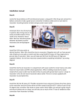
INSTALLATION INSTRUCTIONS
Locating the pump: The macerator is self-priming to a
six foot lift when impeller is wet, four foot when dry, and
may be mounted in any convenient point in the waste
discharge system. It may be mounted in any position or
angle without affecting performance. Use the rubber
grommets provided to absorb vibration. Do not over tighten
mounting screws. For optimal performance, mount the
pump as close to tank as possible.
Plumbing Connections: Use 3" ID non-collapsible hose
and clamp on outside diameter of macerator housing.
All suction connections must be airtight and free of sharp
bends or restrictions to ensure proper priming. Use
minimum 1" ID hose for discharge to direct waste to an
appropriate sewage receiver such as a sewer clean-out.
See recommendation on page 1.
Wiring Hookup: For permanent connection, use heavy
duty stranded copper wire to avoid excessive voltage
drop. Consult recommended wire and fuse size table for
correct size.Install 20 Amp fuse in positive lead between
power source and on-off switch for macerator.
NOTICE: Connect orange wire to positive circuit and black
wire to negative for proper rotation.Failure to connect wires
as described will damage unit and void warranty.
FROM HOLDING TANK TO EXTRA HOLDING TANK
Home Sewer Access
Toilet Bowl
18590-0010
Holding Tank
Sewer Drain
HOLDING TANK PUMP OUT - PERMANENT INSTALLATION
TYPICAL RECREATIONAL VEHICLE USES

EXPLODED VIEW
PARTS LIST
Part
Key Description Qty. Number
1 Acorn Nut 4 91085-0340
2 Fiber Washer 4 91613-0140*
3 Stud 2 17288-0010*
4 Macerator Housing 1 18594-1000
5 Chopper Plate with Locknut 1 37056-1000
6 Wearplate, Large 1 18597-1000
7 Gaskets (2 each per kit) 1 18596-1000*
8 Impeller 1 6303-0003*
9 Wearplate, Small 1 12316-1002
10 Body 1 18593-1000*
11 Seal 1 1040-0000*
12 Slinger 1 6342-0000
13 Stud 2 17288-0000
14 Motor Sub-Assembly-12 volt 1 17246-0000
Motor Sub-Assembly-24 volt 1 17246-0001
Motor Sub-Assembly-32 volt 1 17246-0002
15 Grommets (Set of 4) 1 92900-0120
Service Kit 1 18598-1000
* These parts are supplied in 18598-1000 Service Kit.
DISASSEMBLY
Remove the four acorn nuts (Key 1) and fiber washers
(Key 2) from the pump studs (Key 3). Slide the macerator
housing (Key 4) off the studs. Insert a thin bladed 9/32"
(7mm) ignition wrench behind the chopper plate (Key 5)
and onto the flat of the motor shaft to prevent it from
turning. Unscrew (counter-clockwise) the locknut on the
end of the motor shaft and remove the stainless steel
chopper blade.
†
Remove the pump wearplate (Key 6)
and two paper gaskets (Key 7).Now slide the pump body
(Key 10) with impeller (Key 8), small wearplate (Key 9),
two studs and shaft seal as an assembly off the motor
shaft and remaining two mounting studs. Remove the
starlock retaining washer on the seal and push the seal
out of the seal bore.
If reconditioning pump with a service kit (Part No.18598-
1000), it is not necessary to remove the seal because
the new seal is pre-installed in the new body. It is also
generally not necessary to remove the slinger or brass
studs screwed into the motor end bell.
ASSEMBLY
If installing a new seal, push it into the seal bore of the
body with the lip pointing toward the impeller bore.Press
the starlock washer into the seal bore with the concave
side up to secure the seal in the bore. Install the two
shorter studs in the two holes with threaded inserts in
the new pump body and tighten finger tight. If required,
screw the two longer studs into the tapped holes in the
motor end bell. Slide the new pump body with the shaft
seal installed onto the motor shaft and two long mounting
studs in the motor. Slide the small wearplate over the
motor shaft and position it in the bottom of the impeller
bore. Slide the new impeller onto the motor shaft and,
with a counter-clockwise motion, push it into the pump
impeller bore. Position one new gasket on the studs and
against the pump body assuring the cut-out aligns with
the inlet groove in the body. Position the large wearplate
and second gasket on the studs and against the body
again aligning the hole in the wearplate and gasket cut-out
with the pump inlet. Position the chopper on the end of
the motor shaft with drive tab aligned with flat of shaft
and pointing toward the motor. Hold the shaft with the
ignition wrench and secure the chopper to the shaft with
the locknut. Position the macerator housing on the four
studs ensuring the cut-out in the inner wall aligns with
pump body inlet port and hole in the wearplate. Position
a new fiber washer on each of the studs and secure the
macerator housing in place with the four acorn nuts.
†
On pumps manufactured prior to April of 1998, position a
screwdriver between the prongs of the bronze chopper and
unscrew it (counter-clockwise) and remove it with its lock
washer from the motor shaft.

4-5/8
(117)
2-5/8
(67)
3-5/8
(92)
3/4
(19)
2-1/8
(54)
1" ID Hose Barb
3 DIA.
(76)
2
(51)
2-7/16
(62)
8-1/4
(210)
4-3/4
(121)
1-3/4
(44)
2-3/32
(53)
4-5/32
(106)
U.S.A.
Jabsco
1485 Dale Way, P.O.Box 2158
Costa Mesa, CA 92628-2158
Tel:(714) 545-8251
Fax:(714) 957-0609
UNITED KINGDOM
Jabsco
Bingley Road, Hoddesdon
Hertfordshire EN11 OBU
Tel:+44 (0) 1992 450145
Fax:+44 (0) 1992 467132
CANADA
Fluid Products Canada
55 Royal Road
Guelph, Ontario N1H 1T1
Tel:(519) 821 -1900
Fax:(519) 821-2569
JAPAN
NHK Jabsco Company Ltd.
3-21-10, Shin-Yokohama
Kohoku-Ku, Yokohama, 222
Tel: 045-4758906
Fax: 045-475-8908
GERMANY
Jabsco GmbH
Oststrasse 28
22844 Norderstedt
Tel:+49-40-53 53 73 -0
Fax:+49-40-53 53 73 -11
© Copyright 2000, ITT Industries Printed in U.S.A. All Rights Reserved Form: 43000-0472 Rev. 3/2001
DIMENSIONAL DRAWING
Inches (Millimeters)
ONE YEAR LIMITED WARRANTY
A. LIMITED WARRANTY: Jabsco warrants that at the time of
shipment, the products manufactured by Jabsco and sold hereunder
shall be in conformity with applicable written specifications and descriptions
referred to or set forth herein, free from defects in material and workmanship
,
merchantable, and suitable for a particular purpose, provided such is
implied by State law under the circumstances of this sale.
B.WARRANTY ADJUSTMENT:
1. Jabsco agrees to repair or furnish a replacement for, but not to
remove or install, any product or component thereof which, within
one (1) year from date of purchase, shall upon test and examination
by Jabsco prove defective within the above warranty. Receipt verifying
purchase date is required to obtain adjustment.
2. Buyer shall notify Jabsco of any defect within this warranty no later
than ninety (90) days after the defect is discovered.
3. No product will be accepted for return or replacement without the
prior written authorization of Jabsco. Upon such authorization, and
in accordance with instructions from Jabsco, the product will be
returned to Jabsco, shipping charges prepaid by Buyer. Products
returned to Jabsco will be addressed as follows:
JABSCO
1485 Dale Way
Costa Mesa, California 92626-3998
Or to such alternate locations as may be designated on the product,
its container, or this sheet.
Repair or replacement made under this warranty will be
shipped prepaid to Buyer
C. EXCLUSIONS FROM WARRANTY AND LIMITATION OF LIABILITY:
1. The foregoing warranty is limited solely as set forth herein and
applies only for the period designated above.
2. JABSCO SHALL NOT BE LIABLE FOR ANY LOSS, DAMAGE,
SPECIAL OR CONSEQUENTIAL DAMAGE OF ANY KIND,
WHETHER BASED UPON WARRANTY, CONTRACT,
NEGLIGENCE, OR STRICT LIABILITY ARISING IN CONNECTION
WITH THE SALE,USE, OR REPAIR OF THE PRODUCT.
3. THE MAXIMUM LIABILITY OF JABSCO IN CONNECTION WITH
THIS WARRANTY SHALL NOT IN ANY CASE EXCEED THE
CONTRACT PRICE FOR THE PRODUCT CLAIMED TO BE
DEFECTIVE OR UNSUITABLE.
4. This warranty does not extend to any product manufactured by
Jabsco which has been subjected to misuse, neglect, accident,
improper installation, or use in violation of instructions furnished by
Jabsco.
5. This warranty does not extend to or apply to any unit which has
been repaired or altered at any place other than Jabsco's factory,
or by persons not expressly approved by Jabsco, nor to any unit the
serial number, model number, or identification of which has been
removed, defaced or changed.
6. Components manufactured by any supplier other than Jabsco shall
bear only that warranty made by the manufacturer of that product.
7. This warranty applies to products defined as "consumer products"
by the Consumer Product Warranties Act as from time to time
amended.
D. CONSUMER RIGHTS: This warranty gives you specific legal rights,
and you may have other rights which vary from state to state. Some
states do not allow exclusion or limitation of damages.
STANDARD WARRANTY: If the products manufactured and sold
hereunder are not Consumer Products, the warranty extended to
Buyer shall be as set forth in subparagraphs (A), (B), and (C),
EXCEPT THAT ALL EXPRESS OR IMPLIED WARRANTIES OR
MERCHANTABILITY OR SUITABILITY FOR ANY PARTICULAR
PURPOSE ARE EXCLUDED.
THE PRODUCTS DESCRIBED HEREIN ARE
SUBJECT TO THE JABSCO ONE YEAR LIMITED
WARRANTY, WHICH IS AVAILABLE FOR YOUR
INSPECTION UPON REQUEST.
/