Page is loading ...

1
ATTENTION:
Thank you for purchasing the VD-8810 wireless video door intercom.
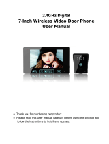
Before permanently mounting the camera door unit on the wall, please conrm successful
wireless signal transmission by testing the quality of the voice and video image.
Before installation and use, please read this instruction manual thoroughly and keep it safe
for future reference.
Instruction Manual
VD-8810 Wireless Video Door Intercom

2
Introduction and installation
Miscellaneous
Using the system
Introduction
Index........................................................................................ 02
What’s included in your kit............................................ 03
Safety precautions............................................................ 04
Operation guidelines......................................................... 04
Identifying the key system components
Camera Door unit.............................................................. 06
Portable LCD Display unit.............................................. 06
LCD Display..................................................... ...................... 07
Installation
Selecting a location for the Camera Door unit..... 08
Installing the Camera Door unit.................................. 10
Charging the Indoor Portable LCD Display unit.... 12
Wall mounting the Charging Cradle.......................... 13
Setting the Date and Time............................................. 14
Using the system
Answering a caller............................................................. 15
Adjusting the Brightness & Volume........................... 16
Live Browsing...................................................................... 17
Recording Video Images................................................. 18
Changing the number of images recorded............ 18
Using the SNAP feature................................................. 19
Viewing the recorded images...................................... 19
Deleting the recorded images..................................... 19
Other functions
Night-time illumination..................................................... 20
Pairing..................................................................................... 20
Replacing the rechargeable battery pack.............. 21
Caring for your system................................................... 22
Troubleshooting................................................................. 23
IQ America Two Year Warranty.................................. 25
Index

3
Main units
1 x Camera Door Unit
1 x Indoor Portable LCD Display Unit
1 x Charging Cradle
Accessories
1 x AC Adaptor
1 x Rechargeable Battery pack
4 x Mounting Screws
4 x Screw Pegs
1 x Instruction Manual
What’s included in your kit

4
Operation guidelines
Avoid using the Indoor Portable LCD Display Unit in the following areas
• Close to a re, thermal appliance or other source of extreme heat/cold.
• Within 3m of a television, microwave oven, personal computer, wireless LAN
equipment, wireless audio/visual equipment - the radio frequency waves
emitted by these devices can affect operation.
• In direct sunlight.
• Where extreme uctuations in temperature can occur - if moving the unit
from a warm to cold environment, or vice versa, please allow 30 minutes
before use.
Please observe the following precautions when installing or using the kit.
Rechargeable Battery Pack
Do not disassemble the battery pack.
Do not dispose of in re.
Use only the specied battery pack in the kit.
Do not use this battery pack in other equipment.
Only charge the battery pack using the charging cradle & AC adaptor supplied.
Do not bring the battery terminals (+/-) into contact with a metal surface/object.
Do not hold the battery pack by the wires.
Should any liquid leak from the battery pack, avoid contact with your skin or eyes.
Indoor LCD Display Unit
Ensure the AC adaptor is securely plugged into the main power outlet.
Do not use within 22cm of a person wearing a cardiac pacemaker - the operation of
the pacemaker could be affected.
Do not install/use in damp, steamy or dusty environments.
Do not hold the LCD monitor to your ear - your hearing could be damaged.
Do not install in an unstable location or where subject to strong vibration.
Safety precautions

5
The following can also affect successful operation of the system
• Metal doors and shutters.
• Walls with aluminium foil insulation.
• Concrete or galvanized metal walls.
The effective communication range is 100m in free air space (line of sight). This
range will be signicantly reduced by the number and thickness of walls through
which the signal is required to pass - please keep to a minimum wherever possible.
This unit shares a frequency band with a wide range of equipment: i.e. industrial,
scientic and medical equipment, licensed and unlicensed low-power radio
transmitters such as those used for RFID applications in factories/warehouses
and amateur radio stations. Before use please conrm that no such equipment is in
use in your vicinity.
In the event that this unit causes unwanted interference to such device, please
discontinue use immediately and contact the customer service center for
consultation on interference avoidance measures.
Privacy & portrait/image rights
• Please respect the privacy and image rights of others when using this
equipment. By using this equipment the user assumes total responsibility in
upholding these rights.
• Images stored must not be used for any purpose other than that for which the
equipment is designed.
• Images should be deleted once no longer required - see page 19 for details of
how to delete the stored images.
About the radio frequency transmitter
• This unit transmits a wireless signal in the frequency range 2.4
- 2.4835GHz.
• The modulation system is GFSK and the interference-causing
radius is 80m.

6
Identifying the key system components
Note:
- Visitor image will be impaired if the ambient backlight is very strong.
- The video image is displayed in color during daytime or in well-lit area, but it is
displayed in black and white at night or in dark area.
Camera lens
Speaker
Battery compartment
Camera unit adjustment
Pairing button
Wall mounting plate
Indication light
Camera Door Unit
Removal of wall
mounting plate
Microphone
Push button
Terminals for external 6V supply
Portable LCD Display Unit
Microphone
Rechargeable
battery pack
Speaker
LCD display
“Talk” button
Accept incoming call
“Scroll” buttons
Select menu items
Adjust volume
“Snap” button
Record camera view
“Browse” button
Instant view of camera
“Brightness” button
Adjust LCD image
brightness
“Play” button
Playback recorded images
“Off” button
End conversation
Power off
Battery cover

7
1
2
3
4
RF transmission condition
Excellent
Good
Weak
None
1
Battery power condition indicator
(Portable Indoor Display Unit)
2
Excellent
• Battery status after 6 hours full charging.
• Operation temperature at 20 deg. C
• Continuous talking: 2 hours
• Standby: 120 hours
Good
Low
• Please charge the battery.
Flat
LCD Display
Date and time indications
The date and time is displayed at the
bottom of the screen.
(For date and time setting See page 17)
4
3
Low battery indicator
(Camera door unit)
• When the camera batteries are
running low, the icon will blink at the
upper right corner of the screen
for 10 seconds during talking or live
browsing.
• Based on average 3 x 10 second
activations per day, the estimated
battery life is approx. 5 months.

8
Selecting a location for the Camera Door Unit
1) Areas to avoid when mounting the door camera unit
The performance of the system may be affected when mounting the unit in the
following areas -
• Areas that are subjected to vibration or shock.
• Near a source of hydrosulphuric, phosphorus, ammonia, sulphur, carbon, acid,
dust and noxious fumes.
• An enclosed area that may cause echo
• Where rain or water may directly hit the back of the unit.
The video image may be seriously impaired where the camera faces directly into
the sun, and also in the following situations.
SKY
WHITE
WALL
1
2 3
Location where the background is primarily occupied by the sky, such as in
the upper oor of an apartment building.
Location which has an adjacent white wall that will directly reect sunlight.
Location that receives direct bright sunlight.
1
2
3
Installation

9
2) Camera position & Field of View (FOV)
The Camera Door Unit can be mounted in a variety of locations. Review the
information below before installation. It is suggested that you experiment with
different mounting locations by holding the camera in position, pressing the doorbell
pushbutton then checking the image on the LCD monitor.
The diagrams below show an example camera position to view a visitor 500mm
from the camera.
• Camera tilt angle = 0 Deg. (this is the default setting).
• Camera mounting height approx. 1500mm
SIDE VIEW
1500mm
1290mm
420mm
46 Deg.
500mm
1710mm
SHOOTING AREA
TOP VIEW
SHOOTING AREA
500mm
560mm
59 Deg.
The Camera Door Unit can be mounted in a lower position or on the left or right
side. The target shooting area can be adjusted as shown below.
• Camera tilt angle = 15 Deg. (upward).
• Lower mounting height approx. 1100mm
• Camera pan angle = 15 Deg. (to the right).
• Camera mounted to left side
1100mm
1030mm
420mm
46 Deg.
500mm
1710mm
SIDE VIEW
500mm
59 Deg.
620mm
TOP VIEW

10
Open the screw cover with a
at blade screwdriver, then
loosen the screw using a
crosshead screwdriver.
1
83.50mm
Mounting screws
Wall mounting plate.
Holes drilled in wall.
Please use the specied batteries only.
Do not mix new and used batteries
CAUTION
Installing the Camera Door Unit
1) Remove the main unit from the mounting base
4) Adjust the camera lens angle
• The camera lens is adjustable to a maximum of 15 degrees.
• Please note that the video image may become slightly distorted if the camera
angle is set to maximum upper left/right adjustment.
Lift to remove the main unit
from the mounting base.
2
2) Fix the mounting base on the wall at the height and location selected
3) Install the batteries
Insert 6 x AA alkaline batteries.
Please ensure to observe the
correct +/- polarity as shown.

11
Angle
adjustment
lever
Adjust camera
view to the left
(max. 15deg.)
Examples of possible camera adjustment
Camera looks
upwards
Adjust camera
view to the right
(max. 15deg.)
Adjust camera
view upwards
(Max. 15deg.)
Camera looks
to the right
Camera looks
up & right
5) Re-t the main unit to the mounting base
• Ensure to secure with the screw and replace the screw cover.
Power supply wires
6) Powering the Camera Door unit via mains power (optional)
The Camera Door unit can be used without batteries by connecting it directly to an
existing 16V wired doorbell supply or 16V external power pack (not supplied).
Remove the main
unit from the
mounting base.
1
Pass the bell wire or the wire
from the power pack through the
mounting plate before xing the
plate to the wall. Connect the wire
to the supply terminals directly.
2
Re-t the main unit
to the mounting
base and secure
with the screw.
3
Power supply wires
Power supply wires
If using an external 16V power pack, it may be
necessary to cut off the attached connector in
order to connect the bare supply wires directly into
the terminals as described in (2) above.
4

12
The indoor portable LCD display unit will need to be charged for approximately 6 - 8
hours before rst use.
• Insert the plug from the AC adaptor into the
socket on the base of the charging cradle. Secure
the cable under the cord grip.
• Fit the charging cradle onto the stand and snap
into place.
Charging the Indoor Portable LCD Display unit.
Remove
the battery
compartment
cover.
1
Connect the battery connector to
the socket located in the battery
compartment. Seat the battery
pack into the compartment.
2
Re-t the battery
cover - do not
remove the foam
cushion.
3
2) Assemble the charging cradle
• A full charge will take around 6 hours,
longer if the unit is used during charging.
• The charging indicator light will extinguish
when charging is complete.
• It’s ok to leave the LCD unit in the charging
cradle - it cannot be over-charged.
• Ensure the charging terminals are kept
free from dust and dirt.
• If the system is not being used for a period
of time, remove the battery pack.
3) Plug the AC adaptor into a 120VAC outlet
4) Place the Indoor Portable LCD Display unit
into the charging cradle
1) Install the battery pack
Charging
indicator light

13
Release
button
Charging stand
Charging
Cradle
The Charging Cradle can either be used free-standing by use of the stand, or wall
mounted as described below.
Wall mounting the Charging Cradle
“UP” marking to the
front side.
Mounting
screws
Mounting
plate
Remove the stand by pressing
down the release button located
behind of the charging stand &
pulling the cradle upwards.
1
Remove the mounting plate from
the charging cradle.
2
Mount the mounting plate to the
wall using the screws and pegs
provided. Ensure the UP marking
is on the front side.
3
Hang the Charging Cradle
securely on the mounting plate
and push it down so that it snaps
in place.
4
Be sure to x the cradle rmly to the wall so that it does not become detached
when inserting/removing the Indoor Portable LCD Display unit.

14
1) Hold the “PLAY” button for 3 seconds.
The date and time will appear with the YEAR highlighted as
shown.
Press the “UP” and “DOWN” arrows to select the year.
2) Press the “PLAY” button to move to the MONTH selection.
Press the “UP” and “DOWN” arrows to select the month.
3) Press the “PLAY” button to move to the DATE selection.
Press the “UP” and “DOWN” arrows to select the date.
4) Press the “PLAY” button to move to the HOUR selection.
Press the “UP” and “DOWN” arrows to select the hour.
Ensure the correct AM/PM setting is selected.
5) Press the “PLAY” button to move to the MINUTE selection.
Press the “UP” and “DOWN” arrows to select the minute.
6) Press the “OFF” button to complete the settings and exit
Date & Time Setting mode.
Setting the Date and Time

15
1) When a visitor presses the pushbutton, ring tones can be
heard and the camera image shows on the LCD monitor.
• A moving image of the visitor will appear for ten seconds
followed by a still image.
• The still image is stored in memory.
• The “OFF” and “ANSWER” buttons will blink slowly.
2) Press the “ANSWER” button to talk to the visitor for up
to 60 seconds.
3) Press the “OFF” button to nish the conversation.
You have 150 seconds to answer a call and initiate a
conversation. If you do not answer a call, an image of the visitor
is stored in memory. The PLAY button will blink slowly to alert you
that a visitor called while you were out - see page 19 “Viewing the
recorded images” for details of how to view the recorded image.
Conversations are limited to a 60 second duration to conserve
battery life should you forget to manually end the conversation by
pressing the “OFF” button.
ANSWER
Key
OFF Key
Answering a caller
Using the system

16
The following adjustments can only be made while the system is operating. The
easiest way to achieve this is to press the doorbell pushbutton and then press the
“ANSWER” button.
Adjusting the Brightness & Volume
1) Changing the Display brightness
• Press the “BRIGHTNESS” button repeatedly until the desired
display brightness is achieved - 5 levels are available.
Default setting
(Level 4)
Maximum
(Level 5)
Sound off
Default setting
(Level 4)
Maximum
(Level 5)
Sound off
2) Changing the voice volume
• Press the “UP” and “DOWN” arrow buttons during the conversation to change
the voice volume - 5 levels are available.
3) Changing the LCD Display unit ringtone volume
• Press the “OFF” button to place the unit in STANDBY
• Press the “UP” and “DOWN” arrow buttons during standby to change the
ringtone volume - 5 levels are available.

17
This function allows you to monitor the view from the Door Camera on the LCD
display at any time. Please note - the Live Browsing feature is only available if the
Door Camera Unit is powered via mains power (see page 11 for details). The
feature is disabled when powered by batteries.
Live Browsing
1) Press the “BROWSE” button.
• The Camera Door unit is activated.
• The LCD monitor will display the
image from the Camera Door unit.
• Sound from the Camera Door unit
microphone can be heard.
Notes:
• After pressing the “BROWSE” or “ANSWER” button, it may take up to 4 seconds for the
‘Live Browsing’ feature to activate.
• Conversations are limited to a 60 second duration to conserve battery life should you
forget to manually end the conversation by pressing the “OFF” button.
3) Press the “OFF” button to exit Live Browsing.
2) Press the “ANSWER” button.
• The Camera Door unit is activated.
• The LCD monitor will display the
image from the Camera Door unit.
• Sound from the Camera Door unit
microphone can be heard.
• You can talk to the person outside
via the LCD monitor.
OR

18
Call
Answered
Still image 1 - captured 1 sec. after call
1 sec
1 sec
1
2
Still image 2 - captured 2 secs. after call
1st image
2nd image
Automatic Recording
Video images are automatically recorded each time a visitor presses the doorbell
pushbutton. Each image has a date and time stamp that indicate when the visit
occurred. The system can store a maximum of 163 images; when this limit is
reached, the oldest image will be automatically deleted to allow a new image to be
stored.
By default, the number of images stored per visit is set to TWO; this can be
changed as described below.
Recording Video Images
1) Press and hold the “SNAP” button for two seconds.
• The options for number of recorded images will appear.
2) Press the “UP” and “DOWN” arrow buttons to select the required number of
images (1, 2 or 3).
3) Press the “OFF” button to complete the settings and exit.
Default setting
(2 images)
Changing the number of images recorded

19
Using the SNAP feature
The SNAP feature allows you to capture and store an image at any time whilst live
video is on the screen of the LCD monitor. The image along with a time and date
stamp is stored.
1st Image
2nd Image
3rd Image
Viewing the recorded images
The recorded images can be viewed at any time.
1) Press the “PLAY” button.
• The most recently stored image will be displayed on
the screen.
2) Press the “UP” and “DOWN” arrow buttons to browse
through the images stored.
3) Press the “OFF” button to exit playback.
NO IMAGE
1) Press the “SNAP” button during live video.
• The screen will indicate that recording is
taking place.
Deleting the recorded images
1) Press and hold the “OFF” and “SNAP” buttons
simultaneously for ve seconds.
2) “NO IMAGE” message will appear on screen and a
beeping sound will be heard - all images are now deleted.
3) Release both buttons.

20
Night-time Illumination
In low light night-time conditions, an infra-red LED light will
illuminate on the Camera Door unit to improve the quality of the
transmitted image. Note that the image will be displayed in black
& white under these conditions.
Pairing
The Door Camera and LCD Monitor are “paired” by a coding system so they will
only communicate with each other. This encoding provides a secure system so
your video and audio are not shared with others. This pairing is taken care of at the
factory for the units contained in your kit, hence no actions are necessary. However,
if for some reason you have to replace the Door Camera unit or LCD Monitor, follow
the procedure below to “pair” the new units together.
1) Remove the Door Camera from it’s mounting bracket to expose the “Pairing”
button.
2) Remove the battery cover from the LCD Monitor to expose the “Pairing” button.
3) Press the “Pairing” button on the Door Camera unit. The LED in the Door
Pushbutton will blink for 30 seconds.
4) Whilst the LED in the Door Camera unit is blinking, press the “Pairing” button in
the LCD Monitor. You will hear ve beeps to indicate that “Pairing” is complete.
Pairing Button
Pairing
Button
Portable indoor display unit Outdoor camera unit
Other functions
/