Page is loading ...

RD2XRT Due to continuing product development, specifications are subject to change without notice
©
2010 RenewAire LLC
138259_001 RD2XRT_BOOK_3.0_SEP10.DOC Revised 9/2010 PAGE 1
AVAILABLE IN B&W OR COLOR AT www.renewaire.com
4510 Helgesen Drive, Madison, WI, 53718
608.221.4499, 800.627.4499, Fax: 608.221.2824
[email protected] www.renewaire.com
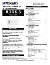
RD2XRT INSTALLATION AND
OPERATION MANUAL
BOOK 3
MECHANICAL
ABOUT BOOK 3:
This book covers the mechanical installation of the
RD2XRT.
See Book 1 for an overview of the RD2X and system
design considerations.
See Book 2 for product and performance
specifications.
See Book 4 for basic electrical connections and
wiring schematics.
See Book 5 for control system connections, VFD
adjustment, Start-Up, Commissioning or
Maintenance.
This book does not cover overall system design or
system integration issues. Some of these issues are
discussed in Books 1 and 5, but in general,
specification documents provided by a qualified
specifying engineer are to be considered the Basis
of System Design.
Following these instructions does not necessarily
assure compliance with local codes and standards,
which must always be observed.
UNPACKING INSPECTION
Move the RD2X to its staging location and remove
packaging. Inspect the unit for visual signs of damage.
Table of Contents
BOOK 1: Overview
Product Features 2
De-Coupled and DOAS System Overview 3
RD2X Psychrometrics 4
System Integration 6
Critical Warnings 7
Checklist for Specifying Engineer 8
BOOK 2: Specifications
Product Features 2
Available Features 3
Descriptive Drawings 4
Configuration Codes 6
Condensed Specifications 8
Dimensions 10
Ratings 12
Modes of Operation 19
Unit Controls and Operating Sequences 20
Connections to External Equipment 22
Guide Specifications 23
BOOK 3: Mechanical Installation
Product Features 2
Order of Installation 3
Critical Dimensions 4
Curb and Rail Dimensions 5
Service Clearances 6
Curb and Rail Installation Considerations 7
Rigging Information 8
Securing the Unit Against Wind Loads 9
Ducting 10
Coil and Drain Connections 11
How to Reconfigure the Inlet and Outlet (opt.) 12
How to Install Field-Supplied Coil (opt.) 14
BOOK 4: Electrical Installation
Product Features 2
Power Connections 3
Disconnect Switch Ratings 5
On-Board Transformer 6
Control Connections 7
Electrical Installation Checklists 8
Schematics 10
Ladder Schematics 18
BOOK 5: Start-Up, Commissioning and Maintenance
Initial Checks 3
Balance Air Flow 4
Review / Adjust On-Board Controls (opt.) 6
VFD Parameters 8
Control Connection Examples: On/Off and 3-speed 11
Analog Control of the VFDs -- General 16
Scaling to VFD Response to Analog Inputs 17
Control Connection Examples: Analog Controllers 22
Control Connection Examples: Mixed Analog & On/Off35
To Reset VFD Parameters 39
Service Parts 40
Warranty Information 48
Records 49

RD2XRT Due to continuing product development, specifications are subject to change without notice
©
2010 RenewAire LLC
138259_001 RD2XRT_BOOK_3.0_SEP10.DOC Revised 9/2010 PAGE 2
AVAILABLE IN B&W OR COLOR AT www.renewaire.com
BOOK 3: MECHANICAL
PRODUCT FEATURES
The RD2X is an Energy Recovery Ventilator with
available features designed for Dedicated Outdoor Air
Systems.
Standard features include:
Energy recovery by fixed-plate enthalpic energy
exchanger
Enthalpy- and temperature-controlled bypass of
energy recovery
Isolation dampers that shut down when ventilation is
not needed
Variable-Frequency Drive (VFD)-controlled direct-
drive fresh air and exhaust air blowers
Integrated disconnect switch
Airflow measurement stations
Available features include:
Heating and/or cooling coils for post-treatment of
fresh air
Double-wall construction
PRINCIPLE OF OPERATION
The RD2X can operate in up to four modes depending
on options installed:
Energy Recovery mode: the unit transfers heating or
cooling energy from the exhaust air to the fresh air.
Recovery Bypass mode: the unit takes advantage of
free cooling from the outside air and doesn’t transfer
energy between air streams.
Dehumidification mode: the unit conditions the fresh
air to 53°F.
Heating mode: the unit tempers the fresh air to 75°F.
The RD2X operates automatically. The unit receives an
external call for ventilation. Its isolation dampers open
and turn on the variable frequency drives and blowers.
The unit determines the operating mode by continuously
monitoring the air streams for temperature and enthalpy.
The RD2X does not include a condensing unit, chiller,
heat pump or boiler. When a coil for dehumidification or
cooling is part of the RD2X unit, the condensing unit,
chiller, heat pump or boiler is separately installed to
meet the needs of the complete system. RD2X units
equipped with coils include connection points to call for
operation of the separate heating or cooling equipment.
However, no fluid or refrigerant flow control valve
(TX valve) is provided, and must be specified by the
designer of the overall system for separate sourcing.
OPERATING CONTROLS
A wide variety of low voltage (24VAC) control schemes
may be selected to meet the ventilation needs of the
facility. These may include time clock, occupancy
sensor, carbon dioxide sensor, and others. DDC
systems may also control the unit with external control
by other. TX valves are not provided.
WARNING
RISK OF FIRE, ELECTRIC SHOCK, OR INJURY.
OBSERVE ALL CODES AND THE FOLLOWING:
1. Before servicing or cleaning the unit, switch power
off at disconnect switch or service panel and lock-
out/tag-out to prevent power from being switched on
accidentally. More than one disconnect switch may
be required to de-energize the equipment for
servicing.
2. This installation manual shows the suggested
installation method. Additional measures may be
required by local codes and standards.
3. Installation work and electrical wiring must be done
by qualified professional(s) in accordance with all
applicable codes, standards and licensing
requirements.
4. Any structural alterations necessary for installation
must comply with all applicable building, health, and
safety code requirements.
5. This unit must be grounded.
6. Sufficient air is needed for proper combustion and
exhausting of gases through the flue (chimney) of
fuel burning equipment that might be installed in the
area affected by this equipment. If this unit is
exhausting air from a space in which chimney-
vented fuel burning equipment is located, take steps
to assure that combustion air supply is not affected.
Follow the heating equipment manufacturer’s
requirements and the combustion air supply
requirements of applicable codes and standards.
7. Use the unit only in the manner intended by the
manufacturer. If you have questions, contact the
manufacturer.
8. This unit is intended for general ventilating only. Do
not use to exhaust hazardous or explosive materials
and vapors. Do not connect this unit to range
hoods, fume hoods or collection systems for toxics.
9. When cutting or drilling into wall or ceiling, do not
damage electrical wiring and other hidden utilities.
10. If installed indoors this unit must be properly ducted
to the outdoors.
CAUTION
To avoid motor bearing damage and noisy and/or
unbalanced impellers, keep drywall spray,
construction dust etc, out of unit.

RD2XRT Due to continuing product development, specifications are subject to change without notice
©
2010 RenewAire LLC
138259_001 RD2XRT_BOOK_3.0_SEP10.DOC Revised 9/2010 PAGE 3
AVAILABLE IN B&W OR COLOR AT www.renewaire.com
BOOK 3: MECHANICAL
ORDER OF INSTALLATION
ESSENTIAL STEPS – CURB MOUNT
PLAN THE INSTALLATION this page
INSTALL CURB page 7
INSTALL DUCTS page 11
RECONFIGURE THE UNIT (if necessary) page 12
MOVE THE UNIT TO THE CURB this page
SECURE THE UNIT TO THE CURB page 7, 9
CONNECT COILS TO HEATING/COOLING EQUIPMENT (if necessary) page 11
CONNECT POWER AND CONTROLS TO UNIT BOOK 4
ESSENTIAL STEPS – RAIL OR PLATFORM MOUNT
PLAN THE INSTALLATION this page
INSTALL RAILS OR PLATFORM page 7
RECONFIGURE THE UNIT (if necessary) page 12
MOVE THE UNIT TO THE RAILS OR PLATFORM this page
SECURE THE UNIT TO THE RAILS OR PLATFORM page 7, 9
INSTALL DUCTS page 11
CONNECT COILS TO HEATING/COOLING EQUIPMENT (if necessary) page 11
CONNECT POWER AND CONTROLS TO UNIT BOOK 4
PLAN THE INSTALLATION
Plan the installation before starting:
• Determine how the unit will be moved to its
installation location, and whether available
equipment can handle the unit. See “RIGGING
INFORMATION”.
• Insure there will be access to the front and rear of
the unit for maintenance and service. See
“SERVICE CLEARANCES”.
• Visualize the ducting layout. If the inlet and outlet
connections on the unit need to be re-configured do
this prior to installation. See “FIELD RE-
CONFIGURATION OF INLET AND OUTLET”.
• Know where the line voltage and control wires are
connected. See “CRITICAL DIMENSIONS”.
• Confirm routing of pipes connected to coils (if
applicable) including the condensate drain line.
MOVE THE UNIT
The RD2XRT is designed for installation outside, on a
roof curb or mounting rails. The unit must be on a level
surface or slightly pitched from back to front of the unit to
allow for proper drainage of the condensate drain pan
out the front of the unit. See “SECURING AGAINST
WIND LOADS” AND “DUCTING’ for additional
information about proper installation locations.
See next page for illustrations of critical dimensions and
weights for moving the unit, and for final location of the
unit.
CAUTION
Do not stand on the unit. Do not stack or store
items on the unit when installed.

RD2XRT Due to continuing product development, specifications are subject to change without notice
©
2010 RenewAire LLC
138259_001 RD2XRT_BOOK_3.0_SEP10.DOC Revised 9/2010 PAGE 4
AVAILABLE IN B&W OR COLOR AT www.renewaire.com
BOOK 3: MECHANICAL
CRITICAL DIMENSIONS
FIGURE 3-1
CRITICAL DIMENSIONS
SHIPPING WEIGHT ON PALLET APPROXIMATELY 1280 LBS.

RD2XRT Due to continuing product development, specifications are subject to change without notice
©
2010 RenewAire LLC
138259_001 RD2XRT_BOOK_3.0_SEP10.DOC Revised 9/2010 PAGE 5
AVAILABLE IN B&W OR COLOR AT www.renewaire.com
BOOK 3: MECHANICAL
CURB AND RAIL DIMENSIONS
FIGURE 3-2
CURB AND RAIL DIMENSIONS

RD2XRT Due to continuing product development, specifications are subject to change without notice
©
2010 RenewAire LLC
138259_001 RD2XRT_BOOK_3.0_SEP10.DOC Revised 9/2010 PAGE 6
AVAILABLE IN B&W OR COLOR AT www.renewaire.com
BOOK 3: MECHANICAL
SERVICE CLEARANCES
FIGURE 3-3
SERVICE CLEARANCES FROM CURB OR RAILS
INSTALLED UNIT WEIGHT: 1158 LBS (varies slightly with installed options)
For installed corner weights, see Book 2 Fig. 2-19.
For weights at lifting lugs, see this book’s Fig 3-4 RIGGING INFORMATION.

RD2XRT Due to continuing product development, specifications are subject to change without notice
©
2010 RenewAire LLC
138259_001 RD2XRT_BOOK_3.0_SEP10.DOC Revised 9/2010 PAGE 7
AVAILABLE IN B&W OR COLOR AT www.renewaire.com
BOOK 3: MECHANICAL
CURB/RAIL INSTALLATION CONSIDERATIONS
CURB OR EQUIPMENT RAILS?
Curbs must be used if either the Fresh Air outlet or the
Return Air inlet is located in the base of the unit.
Equipment Rails may be used if both the Fresh Air outlet
and the Return Air inlet are located in the sides of the
unit.
See Figure 3-2, page 5, for recommended Curb or
Equipment Rail dimensions.
CURB/RAIL HEIGHT
We recommend a minimum 14” curb or rail height from
the structural roof. However, consider local codes and
practice with respect to snow buildup. See Figure 3-1
for distance from top of curb/rail to the OA inlet.
CURB/RAIL LOCATION
The RD unit must be located so that the OA inlet is at
least 10’ from any building air exhaust, sanitary vent
piping, fume hood exhausts, or combustion product
exhausts. Local codes must also be observed.
Curb or rail must be located so that the building structure
can support it. Consider both static loads of the
equipment, seismic loads, and wind loads.
Confirm that the curb/rail location allows for proper
connection of the ducts, electrical power and control
wires, coil and condensate pipes, and provides
necessary service access. See Figure 3-1, page 4 and
Figure 3-3, page 6.
ATTACH CURB OR RAIL TO BUILDING TO
RESIST WIND AND SEISMIC LOADS
Since the curb or rails attach the unit to the building
structure, they must themselves be attached to the
building sufficiently well to transfer wind and seismic
loads, which can be lateral, upward, and downward.
CURB OR RAIL MUST BE LEVEL
The unit must be on a level surface or slightly pitched
from back to front of the unit to allow for proper drainage
of the condensate drain pan out the front of the unit.
CURBS MUST BE INSULATED
Prior to installing the unit, the sides of the curb must be
insulated per the manufacturer’s instructions or as per
standard practice. The curb or rails must also have
roofing and counter-flashing applied as per standard
practice.
DUCTS ARE INSTALLED IN CURB PRIOR
TO UNIT INSTALLATION
Ducts which are to connect to the bottom of the RD unit
must be installed into the Curb and through the roof itself
before the RD unit is placed on the curb.
Do not cut out the entire area of the roof enclosed by the
curb. Openings in the roof for ductwork, electrical and
power and control wiring, and refrigerant or water piping,
should be as small as practical, so that they may be
sealed against air leakage after installation.
GASKET TAPE PROVIDED WITH CURB
MUST BE INSTALLED
Gasket tape is required between the RD unit and a Curb.
The gasket tape should be installed:
- at the entire perimeter of the curb;
- on the top surface of the flanges of the ducts
installed in the curb.
WARNING
DO NOT SUSPEND OR HANG THE UNIT (except as
shown on next page as needed to move the unit to
its installation location). The RD2XRT unit is
designed for installation only on curbs or equipment
rails. Secure the unit to meet applicable wind and
seismic load requirements per applicable codes.
WARNING
The RD2XRT should be moved by qualified
personnel only. Failure to do so can result in death
or serious injury.

RD2XRT Due to continuing product development, specifications are subject to change without notice
©
2010 RenewAire LLC
138259_001 RD2XRT_BOOK_3.0_SEP10.DOC Revised 9/2010 PAGE 8
AVAILABLE IN B&W OR COLOR AT www.renewaire.com
BOOK 3: MECHANICAL
RIGGING INFORMATION
FIGURE 3-4
RIGGING INFORMATION
Unit weight: 1110 LBS without hoods
(varies slightly with options installed)

RD2XRT Due to continuing product development, specifications are subject to change without notice
©
2010 RenewAire LLC
138259_001 RD2XRT_BOOK_3.0_SEP10.DOC Revised 9/2010 PAGE 9
AVAILABLE IN B&W OR COLOR AT www.renewaire.com
BOOK 3: MECHANICAL
SECURING AGAINST WIND LOADS
WARNING
Danger of roof damage or severe injury if high winds
move this unit. Secure unit to structure. Observe
local code requirements.
RenewAire strongly recommends that you secure
rooftop units properly to the curb or equipment rails, and
thus to the building structure. Strong winds, tornados,
and hurricanes can and do displace or remove rooftop
equipment from rails or curbs. When this happens, the
equipment, adjacent roof structure, and even vehicles
parked near the building can be damaged, and rain
typically enters the building. The equipment is put out of
service and the collateral damage can be very
expensive.
At a minimum, observe locally applicable codes, but note
that even if local codes require some attachment means
that may not be enough to withstand common wind
occurrences.
AVAILABLE CURB CLIP KIT
Shown above is one option for securing the RD2XRT
unit against winds up to 90MPH. The available
2XRDCC Curb Clip Kit includes clips and hardware.
Clips must be installed as shown before the RD2XRT
unit is placed on the curb, using supplied hardware.
The curb itself also must be properly secured to the roof
decking. Further information is available in the Curb
Clips Installation Manual.
FIGURE 3-5
SECURING AGAINST WIND LOADS USING AVAILABLE CURB CLIP KIT

RD2XRT Due to continuing product development, specifications are subject to change without notice
©
2010 RenewAire LLC
138259_001 RD2XRT_BOOK_3.0_SEP10.DOC Revised 9/2010 PAGE 10
AVAILABLE IN B&W OR COLOR AT www.renewaire.com
BOOK 3: MECHANICAL
DUCTING
DUCT CONSTRUCTION
GENERAL:
• Follow SMACNA guidelines for duct construction
and airtightness.
• Follow duct design specified in construction
documents in order to achieve design system
airflows.
DUCTS CARRYING AIR AT DIFFERENT
TEMPERATURE THAN SURROUNDINGS:
If any ducts connected to the RD unit pass through
unconditioned spaces, they must be insulated, with a
sealed vapor barrier on both inside and outside of the
insulation.
CAUTION
Danger of condensation and resultant equipment
damage or biological growth if ducts are not properly
installed, sealed and insulated. Observe guidelines
above as well as all applicable codes.
Figure 3-6
AIRFLOW PATHS IN UNIT
DESCRIPTION OF AIRFLOWS
Outside Air (OA) pass through the Outside Air Inlet
Hood, entering the top right hand compartment of the
unit. It passes through the energy exchange core or the
bypass passage. The Fresh Air (FA) then flows through
the coil, if present, and exits the blower and unit at the
bottom left hand compartment. The Return Air (RA)
inside the building enters the bottom right hand
compartment of the unit and flows through the energy
exchange core. The Exhaust Air (EA) then exits the
blower and unit at the top left hand compartment. See
Figure 3-6.
LOCATE THE UNIT FOR GOOD AIR
QUALITY
Locate the unit where un-contaminated air is available.
The exhaust outlet should not dump air into an enclosed
space or any other structure, nor onto a walkway.
WARNING
The fresh air inlet should be at least 10’ away from
any exhaust, such as dryer vents, chimneys, furnace
and water heater exhausts, or other sources of
contamination or carbon monoxide. Do not locate
the fresh air inlet where vehicles may be serviced or
left idling. Never locate the fresh air inlet inside a
structure.

RD2XRT Due to continuing product development, specifications are subject to change without notice
©
2010 RenewAire LLC
138259_001 RD2XRT_BOOK_3.0_SEP10.DOC Revised 9/2010 PAGE 11
AVAILABLE IN B&W OR COLOR AT www.renewaire.com
BOOK 3: MECHANICAL
COIL AND DRAIN CONNECTIONS
When dehumidification or heating coils are part of the
RD2X unit, the coils must be connected to separate
equipment external to the unit. All connecting lines
should be supported independently of the unit. Do not
rely on the connection to the coil to support the pipes.
DIRECT EXPANSION COIL
The liquid (supply) line should be connected to the
middle connection on the leaving air side for counter-
flow operation
The suction line should be connected to the lower
connection on the entering air side for counter-flow
operation. The suction header is equipped with an
external equalizer connection.
CHILLED WATER COIL
Connections for the chilled water (CW) coil include
supply line and return line. Both connections are
soldered copper. The supply line should be connected
to the lower connection on the leaving air side for
counter flow operation. The coils will vent and drain
through the factory-installed vent and drain fittings when
mounted level for horizontal flow.
HOT WATER COIL
Both connections are soldered copper.
CONDENSATE DRAIN
The unit’s condensate drain pan is removable for easy
cleaning. Keep this in mind when connecting the drain
line and trap. The drain line will need to be removed
from the drain pan when it is necessary to remove the
drain pan for cleaning.
The drain pan has a 3/4” NPT internal threaded
connection to allow for drainage of condensation off the
coil. The inside of the unit is under negative pressure
when operating. A trap needs to be installed to prevent
air leakage into the unit during operation. Minimum
requirements for condensate drain trap are shown
below.
S = 1 inch for each inch of negative pressure plus 1 inch
T = ½ x S + pipe diameter
Figure 3-7
CONDENSATE TRAP DIMENSIONS
WARNING
Installation work and piping must be done by
qualified professional(s) in accordance with all
applicable codes, standards, and licensing
requirements. Piping should be supported
independently.
S
T
Unit on
Base

RD2XRT Due to continuing product development, specifications are subject to change without notice
©
2010 RenewAire LLC
138259_001 RD2XRT_BOOK_3.0_SEP10.DOC Revised 9/2010 PAGE 12
AVAILABLE IN B&W OR COLOR AT www.renewaire.com
BOOK 3: MECHANICAL
HOW TO RECONFIGURE THE INLET AND OUTLET (OPTIONAL)
The RD2X is delivered with the inlets and outlets
configured as ordered. In the event you need to
reconfigure the inlet and/or outlet the RD2X provides
that versatility. Follow the steps below.
TO RECONFIGURE RA INLET
1. Remove the filters and cores from the unit so they
are not damaged during reconfiguration.
2. Remove the patch panel from the desired opening.
Save the patch panel and associated hardware.
3. Loosen the isolation damper from the opening by
removing six screws. Save the associated
hardware. If the damper is located in the floor
remove the brackets from the damper. They are not
needed when the damper is re-located to the side
wall.
4. Remove the duct flange from the side opening, if
present.
5. Re-locate the isolation damper into the desired
opening. It will have to be rotated 180° so the
actuator does not interfere with the filters.
6. Attach the damper with the six screws. Brackets
need to be fabricated if the damper is re-locating
from the side wall to the floor.
7. Place the patch panel in the unused opening and
attach with the saved hardware.
8. When using the side opening place the duct flange
around the opening and attach with screws.
9. Caulk around the perimeter of the duct flange to
provide an air tight seal.
10. Replace the cores and filters.
FIGURE 3-8
RECONFIGURING RA INLET
Remove filters and
cores (Step 1).
Damper screws
accessible from
outside of unit
(Step 3). 3 screws
on each side.
Duct flange
mounted around
side opening
(Steps 4 and 8)
Patch pan
through floor of
unit.

RD2XRT Due to continuing product development, specifications are subject to change without notice
©
2010 RenewAire LLC
138259_001 RD2XRT_BOOK_3.0_SEP10.DOC Revised 9/2010 PAGE 13
AVAILABLE IN B&W OR COLOR AT www.renewaire.com
BOOK 3: MECHANICAL
HOW TO RECONFIGURE THE INLET AND OUTLET (OPTIONAL)
TO RECONFIGURE FA OUTLET
1. Remove the duct flange from the side opening, if
present.
2. Remove the patch panel from the desired opening.
Save the patch panel and associated hardware.
3. Loosen the bolts attaching the blower to the base
plate.
4. Rotate the blower 90° to the desired outlet
orientation.
5. Loosen the four bolts attaching the rail to the base
plate.
6. Slide the motor assembly over to the other side of
the base plate and reattach the rail to the base plate
with four bolts.
7. Attach the blower to the base plate with bolts.
8. Place the patch panel in the unused opening and
attach with the saved hardware.
9. When using the side opening place the duct flange
around the opening and attach with screws.
10. Caulk around the perimeter of the duct flange to
provide an air tight seal.
CAUTION
Motor is heavy. Do not drop. Personal injury or
damage to the equipment can occur.
FIGURE 3-9
RECONFIGURING FA OUTLET
Bolts attaching blower
to base plate (Step 3).
EA blower shown. 4th
bolt not visible.
Duct flange
mounted around
side opening.
Bolts attaching rail to
base (Step 5). EA
blower shown. Back
two bolts not visible.

RD2XRT Due to continuing product development, specifications are subject to change without notice
©
2010 RenewAire LLC
138259_001 RD2XRT_BOOK_3.0_SEP10.DOC Revised 9/2010 PAGE 14
AVAILABLE IN B&W OR COLOR AT www.renewaire.com
BOOK 3: MECHANICAL
HOW TO INSTALL FIELD-SUPPLIED COIL (opt.)
The RD2X can be ordered without a coil for field installation of a coil provided by others. The coil compartment is
designed to accommodate a right hand air flow coil(s). Mounting brackets, drain pans and mounting bolts are provided
with the unit for field installed coils.
CRITICAL COIL DIMENSIONS:
Coil including frame and headers may not exceed 37-3/4” width, 24-1/2” height.
Coil frame must be 8” in depth. If two coils are being installed in series they must be bolted together and must have a
total depth of 8”.
Coil Flange width must be at least 1”.
Coil connections should extend so connections may be made inside the unit. Distributors and distribution lines should be
kept within the volume of the maximum dimensions indicated above. See Figure 3-10, page 15.
Mounting holes must be provided in the coil frame. Installation steps below assume these holes are placed by the
installing contractor.
INSTALLATION STEPS:
1. Remove the center drain pan – slide it out from the front of the coil section.
2. Remove the panels and pans from the front and back of the coil section to expose the coil area.
3. The side drain pans inside the unit do not need to be removed.
4. Drill (16) 3/8” diameter holes in the coil flanges on the air entering side of the coil
(Figure 3-10, “VIEW FROM UPSTREAM”).
5. Drill (5) 3/8” diameter holes in the top coil flange on the air leaving side of the coil
(Figure 3-10, “VIEW FROM DOWNSTREAM”).
6. Install (21) ¼”-20 Tinnerman nuts (provided) on the coil flanges.
7. Calculate the distance between the bottom of the coil and the floor of the coil module when the coil will be installed.
Place a wooden board or other like material on the floor of the module to support the coil in place when installing it.
8. Gently slide the coil between the opening of the front of the coil module and into position. Be careful not to damage
the drain pans.
9. Attach the coil brackets to the coil flanges with (21) ¼”-20 x ¾” bolts and lock washers (provided).
10. Remove the wooden board from under the coil.
11. Drill holes in the back pans as needed for the inlet and outlet connections.
12. Install the front and back pans. Make the holes around the connections air tight.

RD2XRT Due to continuing product development, specifications are subject to change without notice
©
2010 RenewAire LLC
138259_001 RD2XRT_BOOK_3.0_SEP10.DOC Revised 9/2010 PAGE 15
AVAILABLE IN B&W OR COLOR AT www.renewaire.com
BOOK 3: MECHANICAL
HOW TO INSTALL FIELD-SUPPLIED COIL (opt.)
Figure 3-10
CRITICAL DIMENSIONAL REQUIREMENTS FOR FIELD-SUPPLIED COIL(S)

RD2XRT Due to continuing product development, specifications are subject to change without notice
©
2010 RenewAire LLC
138259_001 RD2XRT_BOOK_3.0_SEP10.DOC Revised 9/2010 PAGE 16
AVAILABLE IN B&W OR COLOR AT www.renewaire.com
BOOK 3: MECHANICAL
NOTES
/