SKYDANCE dv User manual

Type
User manual
DALI 0/1-10V Dimmer
2 DALI address, 2 channel 0/1-10V output.
High voltage AC input, one high voltage AC relay output.
0-10V or 1-10V output selectable.
In accordance with DALI standard protocol IEC 62386-101, IEC 62386-102,
IEC 62386-206 and in compliance with DALI products from other international
incorporation.
DALI address can be manually assigned and shown in digital display
or automatically assigned by DALI master.
DALI INPUT
DA1
DA2
L
N
N
L1
AC100-240V
OUTPUT
AC100-240V
INPUT
0/1-10V OUTP UT
CH1+
CH1-
CH2+
CH2-
0-6 0-9
DV
+Single color LED strip
V+
V-
DI M+
DI M-
AC N
AC L
+
V+
V-
DI M+
DI M-
AC N
AC L 0-10V Dimmable Driver
0-10V Dimmable Driver
Single color LED strip
N
L
AC 100-240V DALI
Master
Note:
We recommend the number of LED drivers connected to 0/1-10V dimmer (each channel) does not exceed 20 pieces,
The maximum length of the wires from dimmer to LED driver should be no more than 30 meters.
Wiring Diagram
Technical Parameters
Mechanical Structures and Installations
DV DALI
Page 1
2023.11
User Manual Ver 1.0.2
187.00 mm
46.00 mm
22.00 mm
Setting key Digital display
CH1 0-10V output +
AC L Output
DALI INPUT
DA1
DA2
L
N
N
L1
AC100-240V
OUTPUT
AC100-240V
INPUT
0/1-10V OUTPU T
CH1+
CH1-
CH2+
CH2-
0-6 0-9CH1 0-10V output -
CH2 0-10V output -
CH2 0-10V output +
AC L input
AC N input
AC N Output
DALI signal input, no need
distinguish plus-minus polarity
Output signal 2 x (0/1-10)V, 20mA/CH
Output current Max 5A(AC)
Input and Output
Input voltage 100-240VAC
Gross weight 0.140kg
Dimming data
Dimming range
DALI
0 -100%
Input signal
Operation temperature
Case temperature (Max.)
Environment
IP20
IP rating
Ta: -30
O
C ~ +55
O
C
Tc:
+60
O
C
Dimming curve Linear
Safety and EMC
EMC standard (EMC) ETSI EN 301 489-1 V2.2.3
ETSI EN 301 489-17 V3.2.4
Certication CE,EMC,LVD
EN 62368-1:2020+A11:2020
Safety standard(LVD)
Size
Package
L190x W48 x H25mm Warranty
5 years
Warranty
LVD
DALI Bus
Power Supply
DALI address assigned by DALI masters
DALI address can also be assigned by DALI Master controller automatically.
Please refer to user manuals of compatible DALI Masters for specic operations.
The digital display will show “AU” When the DALI master is assigning address.
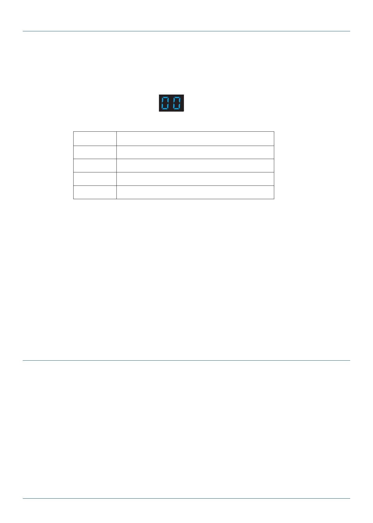
After address is assigned, the digital display will show the start DALI address”xx”, xx is from 00 to 63.
Set DALI address via buttons
Long press any of the two buttons for 2s, prepare for set the start DALI address, digital display start ashes.
Short press left button to set “tens” position and right button to set “units” position.
The address can be set from 00~62-FF. no DALI address is assigned for the dimmer, digital display shows “FF”.
Address assignments are sequential. If the set address value is 01, the CH1 address value is 01, and the CH2 address value is 02, The display shows the
CH1 address value.
Long press any of the two buttons for 2s or timeout 10s, quit start DALI address setting, digital display stop ashes.
Set 0/1-10V output mode
Long press two buttons at the same time for 2s, switch between 1-10V output or 0-10V output.
Press the left / right button to change the output mode.
Long press any of the two buttons for 2s or timeout 10s, quit 0/1-10Voutput mode setting.
Operation
0/1-10V output mode
Mode Channel Output
00
01
10
11
CH 1:0-10V CH 2:0-10V
CH 1:0-10V CH 2:1-10V
CH 1:1-10V CH 2:0-10V
CH 1:1-10V CH 2:1-10V
Page 2
2023.11
User Manual Ver 1.0.2
• DO NOT install with power applied to device.
• DO NOT expose the device to moisture.
Safety & Warnings
  • Page 1 1
  • Page 2 2

SKYDANCE dv User manual

Type
User manual

Ask a question and I''ll find the answer in the document

Finding information in a document is now easier with AI