Page is loading ...

Installation Plan
Commercial Tumble Dryer
PDR528G
Gas-heated
To prevent accidents and machine damage,
read these instructions before installation or
use.
en-US, CA
M.-Nr. 12 376 600

Contents
2
Installation notes ............................................................................................................. 3
Installation requirements ................................................................................................... 3
Floor anchoring ................................................................................................................. 3
Optional accessories......................................................................................................... 3
Communication box...................................................................................................... 3
XKM3200WLPLT ........................................................................................................ 3
Supply air, exhaust, and ventilation cross-sections.......................................................... 4
Supply air/exhaust air ................................................................................................... 4
Calculating the total length and diameter of a supply-air or exhaust pipe ................... 4
Substitute duct lengths................................................................................................. 5
Maximum permissible total ducting length................................................................... 5
Room ventilation opening for air intake from the setup room....................................... 6
Exhaust connection ...................................................................................................... 7
Gas .................................................................................................................................... 12
Take these safety precautions if you smell gas............................................................. 12
1. What needs to be observed before commissioning ................................................. 13
2. What needs to be observed during commissioning ................................................. 15
PDR528, gas heated....................................................................................................... 21
Dimensions........................................................................................................................ 21
Installation ......................................................................................................................... 22
Floor anchoring ................................................................................................................. 23
Technical data.................................................................................................................. 24
Possible voltage options ................................................................................................... 24
Exhaust air......................................................................................................................... 24
Supply air .......................................................................................................................... 24
Gas connection ................................................................................................................. 24
Equipotential bonding ....................................................................................................... 24
APDR002 communication box (optional accessory)........................................................ 25
Machine data..................................................................................................................... 25

Installation notes
3
Installation requirements
Risk of injury or damage to property due to improper installation.
Incorrect installation of the tumble dryer can lead to personal injury or damage to prop-
erty.
It is recommended that installation and commissioning be accomplished by MieleSer-
vice or an authorized dealer.
In Massachusetts, installation must be performed by a licensed installer/gas fitter.
The tumble dryer must be installed in accordance with all relevant regulations and stan-
dards. Observe all local codes.
The dryer must only be operated in a room that has sufficient ventilation and which is
frost-free.
The tumble dryer must not be installed behind a closeable door or a sliding door. The
maximum opening angle of the tumble dryer door must not be limited by objects or doors.
It must be possible to fully open the tumble dryer door at any time.
Floor anchoring
Secure the two screw feet at the front of the tumble dryer to the floor with the tensioning
straps supplied.
Optional accessories
Only use genuine Miele spare parts and accessories with this machine.
Using parts or accessories from other manufacturers may void the warranty, and Miele
cannot accept liability.
Communication box
The optional communication box allows external hardware from Miele and other suppliers
to be connected to the MieleProfessional machine. External hardware includes e.g., peak-
load systems, pressure sensors, or an external vent flap.
The communication box is supplied with voltage by the Miele Professional machine.
The separately available set consists of the communication box and fasteners for installa-
tion on the machine or on the wall.
XKM3200WLPLT
The optional Miele communication module can be used to establish a data connection be-
tween a MieleProfessional machine and a data processor in accordance with the Ethernet
or WiFi standard.
This communication module fits into the communication slot which is a standard feature
on all machines. The communication module offers the option of intelligent app-based
communication with external systems. In addition, it can display detailed machine and pro-
gram status information.
This module forms the basis for wired communication with MieleMOVE.
It is not possible to integrate the machine into the “Miele@home” app for domestic in-
stallations.

Installation notes
4
The communication module is intended exclusively for commercial use and is supplied
with voltage directly via the Miele Professional machine. No additional power connection
is required. The Ethernet interface provided via the communication module complies with
SELV (safety extra low voltage) requirements in accordance with EN60950. Connected
external machines must also comply with SELV.
Supply air, exhaust, and ventilation cross-sections
Supply air/exhaust air
The tumble dryer may only be operated when the ducting has been connected properly
and the room is sufficiently ventilated.
Calculating the total length and diameter of a supply-air or exhaust pipe
The length of the required ductwork and the number and shape of the elbows are deter-
mined by the structural conditions on-site. In order to maximize the airflow efficiency, the
pipeline should be as short as possible and contain few or minimal elbows.
The exhaust ducting must not be made from flammable materials.
Otherwise there is a risk of fire.
Use only non-flammable materials for the exhaust ducting. All local regulations for
metallic ducting must be observed. Plastic must not be used for ventilation.
In upward exhaust ducting systems, a condensate drain must be fitted to the bottom. The
condensate must be drained via a water collection tray or a floor drain positioned in an ap-
propriate location.
If air is being directed from multiple appliances into a combined line (exceptional circum-
stances), a non-return device (non-return flap) must be installed in each separate line to
prevent backflow.
To make subsequent cleaning of the pipes easier, cleaning flaps should be fitted to elbows
wherever possible.
The on-site exhaust ducting and venting to the outdoors must be regularly checked for lint
deposits and cleaned if necessary.

Installation notes
5
Substitute duct lengths
Type of el-
bow
Type PDR
914/514
PDR
918/518
PDR
922/522
PDR
928/528
PDR
944/544
90° elbow r=2d 3' 7 5/16" (1.1m)
45° elbow r=2d 2' 3 9/16" (0.7m)
90° elbow r=d 6' 2 13/16" (1.9m)
45° elbow r=d 3' 7 5/16" (1.1m)
90° concertina duct el-
bow
r=2d 10' 6" (3.2m)
45° concertina duct el-
bow
r=2d 6' 6 3/4" (2m)
90° segmented elbow
(3welded seams)
r=2d 3' 11 1/4" (1.2m)
90° elbow, Westaflex
ducting
r=2d
r=4d
3' 11 1/4" (1.2m)
2' 11 7/16" (0.9m)
45° elbow, Westaflex
ducting
r=2d
r=4d
3' 3 3/8" (1m)
2' 7 1/2" (0.8m)
Non-return flap 39' 4 7/16"
(12m)
39' 4 7/16"
(12m)
22' 11 9/16"
(7m)
22' 11 9/16"
(7m)
21' 3 7/8"
(6.5m)
Table1
Maximum permissible total ducting length
Internal minimum pipe diameter
(metal ducting)
PDRx14 G PDRx18 G PDRx22 G PDRx28 G PDRx44 G
5 7/8" (150mm) 62' 4 1/16"
(19m)
49' 2 9/16"
(15m)
39' 4 7/16"
(12m)
32' 9 11/16"
(10m)
32' 9 11/16"
(10m)
7 1/16" (180mm) 164' 1/2" (50m) 124' 8 1/16"
(38m)
101' 8 1/2"
(31m)
88' 7" (27m) 78' 8 7/8"
(24m)
7 7/8" (200mm) 278' 10 7/16"
(85m)
213' 3 1/16"
(65m)
173' 10 5/8"
(53m)
157' 5 3/4"
(48m)
130' (40m)
Permissible counter pressure in the ex-
haust ducting
0.04psi
(280Pa)
0.04psi
(290Pa)
0.04psi
(290Pa)
0.04psi
(290Pa)
0.03psi
(240Pa)
Table2
When connected to the vent ducting through the exhaust duct of a machine, particular
care must be taken to make sure the connection is secure and air-tight.
With complex ducting with many bends and additional components, or when several dif-
ferent machines are connected to a shared duct, it is recommended that a detailed
pipework calculation is carried out by a qualified specialist.

Installation notes
6
The vent ducting must not be channeled into a chimney or flue already in use for any gas-,
coal-, or oil-burning installation. The warm and moist exhaust air is to be conducted out-
side or to a suitable venting duct over the shortest path possible. The vent ducting must
be laid so that air flow is not hindered. To achieve this, use as few bends as possible along
with short pipelines and well-made connections and transitions checked for air-tightness.
No filters or grilles may be fitted in the vent ducting.
The end of the vent ducting leading out into the open should be protected against the ele-
ments, e.g., with a downward-facing 90° bend.
During tumble dryer operation, the room must be adequately ventilated.
Room ventilation opening for air intake from the setup room
The minimum dimension of the ventilation opening depends on the cross-section of the
vent duct.
Vent duct Minimum dimension for ventilation opening
A A
6"(150mm) - 277/16"²
(177cm²)
825/16"²
(531cm²)
101/4"
(260mm)
91/16"
(230mm)
- 6"
(150mm)
347/8"²
(225cm²)
1045/8"²
(675cm²)
115/8"
(295mm)
101/4"
(260mm)
71/16"(180mm) - 393/8"²
(254cm²)
1181/8"²
(762cm²)
123/8"
(315mm)
11"
(280mm)
- 71/16"
(180mm)
501/4"²
(324cm²)
15011/16"²
(972cm²)
14"
(355mm)
123/8"
(315mm)
77/8"(200mm) - 4811/16"²
(314cm²)
146"²
(942cm²)
133/4"
(350mm)
123/16"
(310mm)
- 77/8"
(200mm)
62"²
(400cm²)
186"²
(1,200cm²)
159/16"
(395mm)
133/4"
(350mm)
811/16"(220mm) - 587/8"²
(380cm²)
17611/16"²
(1,140cm²)
15"
(381mm)
1413/16"
(377mm)
- 811/16"
(220mm)
75"²
(484cm²)
2251/16"²
(1,452cm²)
1615/16"
(430mm)
151/16"
(382mm)
913/16"(250mm) - 761/8"²
(491cm²)
2285/16"²
(1,473cm²)
171/8"
(435mm)
153/16"
(385mm)
- 913/16"
(250mm)
967/8"²
(625cm²)
2905/8"²
(1,875cm²)
195/16"
(490mm)
171/8"
(435mm)
113/16"(300mm) - 1099/16"²
(707cm²)
3283/4"²
(2,121cm²)
201/2"
(520mm)
181/8"
(460mm)
- 113/16"
(300mm)
1391/2"²
(900cm²)
4181/2"²
(2,700cm²)
231/4"
(590mm)
201/2"
(520mm)
Table3

Installation notes
7
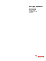
Exhaust connection
1 7/16" (37 mm)
Ø 5 15/16" (150 mm)
Ø 5 15/16" (151 mm)
Example1
Configuring vent ducting made from steel piping for the PDR914/514 tumble dryers:
L1, L2: each 9'10"(3m) steel piping
B1, B2: each 90° concertina pipe elbow (r = 2d)
B3: 90°elbow (r=d)
B3
L1
B1
B2L2

Installation notes
8
1.Total duct length
Steel pipe L1 = 9'10"(3.0m)
Steel pipe L2 = 9'10"(3.0m)
90° concertina pipe elbow
(r=2d)
B1 = 10'6"(3.2m)*
90° concertina pipe elbow
(r=2d)
B2 = 10'6"(3.2m)*
90°elbow (r=d) B3 = 6'3"(1.9m*)
Total duct length 46'11"(14.3m)
* Substitute duct lengths according to Table1
2.Duct diameter depending on total pipe length
For the calculated total pipe length of 46'11"(14.3m) for a PDR 914/514, a minimum duct
diameter of 6"(150mm) is specified for the exhaust ducting according to Table 2.

Installation notes
9
Example2
Common combined exhaust ducting for multiple appliances should only be considered as
a solution in exceptional cases.
Configuring combined exhaust ducting made from steel for the PDR 914/514 and PDR
918/518 series tumble dryers:
L1–L4 each 6'6"(2m) steel piping
B1–B3 each 90° concertina pipe elbow (r = 2d)
B4 45°elbow (r=2d)
B5 90°elbow (r=d)
If the exhaust from multiple appliances is to be ducted into a combined line, a non-return
device must be installed in each separate line to prevent backflow.
B2
L1
B1 B3
L2 L4 B5
B4
L3
PDR 914/514 PDR 918/518

Installation notes
10
1.Total pipe length PDR914/514
Steel pipe L1 = 6'6"(2.0m)
Steel pipe L2 = 6'6"(2.0m)
Steel pipe L4 = 6'6"(2.0m)
90° concertina pipe elbow
(r=2d)
B1 = 10'6"(3.2m)*
90° concertina pipe elbow
(r=2d)
B2 = 10'6"(3.2m)*
90°elbow (r=d) B5 = 6'3"(1.9m*)
Total duct length 14.3m
* Substitute pipe lengths according to Table1
2.Pipe diameter depending on total pipe length
Total pipe length=46'11"(14.3m)
Maximum permissible total pipe length 62'4"(19m)=Ø6"(150mm) internal pipe diame-
ter (see Table2)
3.Total pipe length PDR918/518
Steel pipe L3 = 6'6"(2.0m)
Steel pipe L4 = 6'6"(2.0m)
90° concertina pipe elbow
(r=2d)
B3 = 10'6"(3.2m)*
45°elbow (r=2d) B4 = 2'3"(0.7m)*
90°elbow (r=d) B5 = 6'2"(1.9m)*
Total duct length 32' 1 13/16" (9.8m)
* Substitute pipe lengths according to Table1
4.Pipe diameter depending on total pipe length
Total pipe length =32' 1 13/16" (9.8m) (PDR918/518)
Maximum permissible total pipe length 49'2"(15m)=Ø6"(150mm) internal pipe diame-
ter (see Table2)
5.Total duct diameter
According to Table3
Duct diameter PDR914/514 Ø6"(150mm)
=273/8"²(177cm²)
Duct diameter PDR918/518 Ø6"(150mm)
=273/8"²(177cm²)
Total cross sectionA = 5413/16"²(354cm²)
Total duct diameter = Ø811/16"(220mm)

Installation notes
11
Example3
Configuring exhaust ducting and a supply pipe made from steel for the PDR914/514 se-
ries tumble dryer:
L1, L2: each 6'6"(2.0m) steel piping
L3: 8'2"(2.5m) steel piping
B1, B2: 90° concertina pipe elbow for each
B3, B4: 90°elbow (r=d) for each
B2
L2
B3
L1
L3
B4
B1
1.Total duct length
Steel pipe L1 = 6'6"(2.0m)
Steel pipe L2 = 6'6"(2.0m)
Steel pipe L3 = 8'2"(2.5m)
90° concertina pipe elbow B1 = 10'6"(3.2m)*
90° concertina pipe elbow B2 = 10'6"(3.2m)*
90°elbow (r=d) B3 = 6'3"(1.9m*)
90°elbow (r=d) B4 = 6'3"(1.9m*)
Total duct length 54' 9 1/2" (16.7m)
* Substitute pipe lengths according to Table1
2.Pipe diameter depending on total pipe length
For the calculated total pipe length of 54'9"(16.7m) for a PDR914/514, a minimum pipe
diameter of 6"(150mm) is specified for the exhaust ducting and supply pipe according to
Table 2.

Installation notes
12
Configuring the room ventilation opening
Rooms in which rotary irons and tumble dryers are operated must have an induced
ventilation system (e.g., ventilation slots in windows and doors, wall openings with
grilles, or opened windows or skylights).
For example1
A duct diameter of 6"(150mm) was specified in example1. According to this duct diame-
ter, a room ventilation opening with a size of 17'5"(531cm) is required. The edge length is
91/16"(230mm) (see Table3).
For example2
A total duct diameter of 811/16"(220mm) was specified. According to this duct diameter,
a room ventilation opening with a size of 37'4"(1,140cm) is required. The edge length is
1413/16"(377mm) (see Table3).
For example3
Since in this case the tumble dryer is connected to a central air supply, additional ventila-
tion openings are not needed.
Gas
Take these safety precautions if you smell gas
- Extinguish all flames immediately.
- Close the on-site gas shut-off device, the gas shut-off device on the gas meter or the
main gas shut-off device immediately.
- Open all windows and doors immediately.
- Do not light any naked flames (e.g., matches or lighters).
- Do not smoke.
- If there is the smell of gas in a room, never enter the room with an open flame.
- Do not carry out any actions that will create electrical sparks (such as pulling out electri-
cal plugs or pressing electrical switches or bells).
- If you cannot find the cause of the gas smell and all gas valves have been shut off,
please call the gas supply company immediately.
If other persons are being shown how to operate the machine, they must be given and/
or made aware of these important safety precautions.
During installation, the technical regulations for gas installations as well as national and
regional building regulations, fire regulations, and specifications from the relevant gas
supply companies must be adhered to.
When planning a gas-heated system, contact the relevant gas supply company and a
building regulations inspector.

Installation notes
13
1. What needs to be observed before commissioning
Please specify the gas type, gas group, and connection pressure.
Installation site
Gas-heated tumble dryers must not be operated in a room where cleaning machines oper-
ate with solvents containing perchloroethylene or CFCs. During combustion, any vapors
that are emitted will break down into hydrochloric acid, leading to consequential damage
affecting laundry and the machine. Air exchange must not take place if machines are set
up in separate rooms.
Rooms with fuel-burning installations must be adequately aerated and ventilated. Any gas-
heated machine must be considered to be a fuel-burning installation (regardless of its gas
flow rate).
If liquid gas-heated machines are being set up below ground level, the operator must pro-
vide the system with the necessary aeration and induced ventilation equipment in accor-
dance with technical regulations for liquid propane.
If no low pressure occurs when a full fire is burning in all fuel-burning installations, this
means that the room ventilation is working properly, even if the exhaust gases from the in-
stallations are being extracted mechanically. This ensures that the gas is being combusted
correctly and that the exhaust gases are being evacuated completely.
It must not be possible to seal off aeration and ventilation openings.
Before completing commissioning, maintenance, conversion, and repair work, all
gas-conducting components – from the manual shut-off valve to the burner jet – must
be checked for leaks.
Particular attention must be paid to the measuring stubs on the gas valve. Checks must
be performed when the burner is both switched on and switched off.
Installing thermal shut-off equipment on site is recommended.
If gas-heated appliances are accessible to anyone, it is also necessary to check whether
a gas flow monitor needs to be used.
Gas supply
Required flow rate
Appliance type Rated heat load (Hi) Natural gas Liquid propane
PDR914/514 15kW 0.936CFM
(1.59m³/h)
2.6lb/h
(1.18kg/h)
PDR918/518 18kW 1.118CFM
(1.90m³/h)
3.13lb/h
(1.42kg/h)
PDR922/522 21.5kW 1.342CFM
(2.28m³/h)
3.75lb/h
(1.70kg/h)
PDR928/528 30kW 1.866CFM
(3.17m³/h)
5.22lb/h
(2.37kg/h)
PDR944/544 36kW 2.242CFM
(3.81m³/h)
6.26lb/h
(2.84kg/h)

Installation notes
14
The connected load is based on the following consumption calorific values:
Natural gas: 913BTU/ft³ (34.02MJ/m³) (Hi))
Liquid propane: 19,625BTU/lb (45.65MJ/kg (Hi))
Natural gas
Natural gas Length of gas line
9' 10" (3 m) 15" (5 m) 32' 9 11/16"
(10 m)
65' 7 3/8" (20
m)
98' 5 1/8" (30
m)
164' 1/2" (50
m)
328' 1" (100 m)
Internal diam-
eter Maximum flow rate
¾" (20 mm) 2.766 CFM
(4.7 m³/h)
2.177 CFM
(3.7 m³/h)
1.53 CFM (2.6
m³/h)
0.942 CFM
(1.6 m³/h)
0.647 CFM
(1.1 m³/h)
0.412 CFM
(0.7 m³/h)
0.177 CFM
(0.3 m³/h)
1" (25 mm) 5.061 CFM
(8.6 m³/h)
4.061 CFM
(6.9 m³/h)
2.825 CFM
(4.8 m³/h)
1.824 CFM
(3.1 m³/h)
1.412 CFM
(2.4 m³/h)
1.118 CFM
(1.9 m³/h)
0.53 CFM (0.9
m³/h)
1 ¼" (32 mm) 9.416 CFM
(16.0 m³/h)
7.297 CFM
(12.4 m³/h)
5.12 CFM (8.7
m³/h)
3.649 CFM
(6.2 m³/h)
2.942 CFM
(5.0 m³/h)
2.236 CFM
(3.8 m³/h)
1.412 CFM
(2.4 m³/h)
1 ½" (40 mm) 15.595 CFM
(26.5 m³/h)
12.064 CFM
(20.5 m³/h)
8.533 CFM
(14.5 m³/h)
6.062 CFM
(10.3 m³/h)
4.943 CFM
(8.4 m³/h)
3.825 CFM
(6.5 m³/h)
2.354 CFM
(4.0 m³/h)
2" (50 mm) 35.31 CFM
(60.0 m³/h)
27.66 CFM
(47.0 m³/h)
19.421 CFM
(33.0 m³/h)
13.536 CFM
(23.0 m³/h)
11.181 CFM
(19.0 m³/h)
8.828 CFM
(15.0 m³/h)
5.885 CFM
(10.0 m³/h)
Liquid propane
Liquid
propane
Length of gas line
15" (5 m)m 32' 9 11/16"
(10 m)m
65' 7 3/8" (20
m)m
164' 1/2" (50
m)m
Internal diam-
eter
Maximum flow rate
3/8" (10
mm)mm
2.87 lb/h (1.3
kg/h)kg/h
2.2 lb/h (1.0
kg/h)kg/h
- -
1/2" (12
mm)mm
4.41 lb/h (2.0
kg/h)kg/h
3.31 lb/h (1.5
kg/h)kg/h
2.2 lb/h (1.0
kg/h)kg/h
-
5/8" (16
mm)mm
8.82 lb/h (4.0
kg/h)kg/h
6.61 lb/h (3.0
kg/h)kg/h
4.41 lb/h (2.0
kg/h)kg/h
3.31 lb/h (1.5
kg/h)kg/h
7/8" (22
mm)mm
19.84 lb/h (9.0
kg/h)kg/h
14.33 lb/h (6.5
kg/h)kg/h
9.92 lb/h (4.5
kg/h)kg/h
6.61 lb/h (3.0
kg/h)kg/h
1 1/16" (27
mm)mm
- 26.46 lb/h
(12.0 kg/h)kg/
h
17.64 lb/h (8.0
kg/h)kg/h
11.02 lb/h (5.0
kg/h)kg/h
Exhaust gas evacuation ducts
Gas-heated MieleTumble Dryers are type B22 gas fuel-burning installations without flow
safeguarding equipment, and with a fan behind the heater.
- The mixtures of exhaust gas and air that are emitted by gas-heated tumble dryers must
be evacuated through a suitable chimney and out into the atmosphere via the roof.
- Exhaust air evacuation ducts and exhaust gas evacuation ducts must be kept as short
as possible. The evacuation ducts must rise vertically up to the flue.
- Only materials that are resistant to heat and sooting may be used.

Installation notes
15
- A condensate drain must be placed at the lowest point of the exhaust ducting. The con-
densate must be drained via a water collection tray or a floor drain positioned in an ap-
propriate location. No filters or grilles may be fitted in the pipeline. The exhaust air or ex-
haust gas ducting must be installed leak-tight.
Compliance with the latest guidelines for approving exhaust gas systems containing low-
temperature exhaust gases must be assured.
Exceptions
1. Where it is not possible for evacuation to take place through a single duct, appropri-
ate measures must be taken to ensure that the exhaust gas/air mixture from the ma-
chine is not able to enter the room in which the machine is located via the exhaust
duct for other machines (e.g., through the use of baffles and merged lines that do not
hinder the flow). When selecting and installing equipment that will not hinder the flow,
it is important to ensure that high pressure cannot arise at the side that is not being
operated. Machines fitted with fans must not be connected to the same vent flue as
those without fans.
2. When evacuating the exhaust gas/air mixture through the exterior wall, no dangers or
unreasonable nuisance may arise.
3. With a combined line, the exhaust air ducts for the individual machines must be in-
stalled horizontally in the combined line in a way that does not hinder the flow. The
cross-section of the vent flue must not be smaller than the cross-section of the com-
bined line. Combined lines must be kept as short as possible and must rise vertically
up to the vent flue. A condensate drain is required at the lowest point.
All exceptional cases, and particularly those where a combined line is being installed, re-
quire special permission from the relevant building regulations inspector supervisor’s of-
fice.
Diameter and cross-section of the exhaust ducting
Tumble dryers Exhaust gas connection
Diameter/cross-section
PDR914/918/922/928/944/514/518/522/528/544 6"/271/4"(150mm/176cm²)
2. What needs to be observed during commissioning
Check that the points listed in section 1 (“What needs to be observed before commission-
ing”) have been taken into consideration. The following should be carried out in the given
order when commissioning or converting the appliance:
1. Ask the gas supply company what the gas type, gas group, and connection pressure
are, and compare this information with the data specified on the tumble dryer (see the
sticker at the rear).
2. Check the factory-set jet pressure based on the tables "Settings with natural
gas"/"Settings with liquid propane" and correct it if necessary.
3. If the gas type, gas group, or connection pressure is different, it must be converted as
instructed in the section entitled “Connection and conversion instructions” and the
sticker at the rear of the tumble dryer must be replaced accordingly.

Installation notes
16
4. If the gas type needs to be changed, please request the appropriate conversion kit
from MieleService. When doing so, please specify the product name and the appli-
ance number, as well as the gas type, gas group, gas connection pressure, and
country where the appliance has been set up.
5. Set the jet pressure at the tumble dryer’s gas regulating valve (see tables "Settings
with natural gas"/"Settings with liquid propane").
6. Switch on all gas consumers that are present (including the installed tumble dryer).
7. Measure the connection pressure. The connection pressure must be within the
ranges specified in local guidelines.
Connection and conversion instructions
Connection and conversion work must be performed by MieleService or by an autho-
rized dealer.
The settings for tumble dryers are made at the factory in line with the gas specifications at
the rear of the appliance.
Gas hose
The gas appliance must be connected using a corrugated metal hose assembly made from
stainless steel in accordance with DIN3384. Alternatively, a hose that complies with
DINEN16617 may be used with connections in accordance with DIN3384.
The maximum length of the hose is 6' 6" (2m). When selecting a hose, the required flow
rate and applicable national regulations must also be taken into account.

Installation notes
17
Main connection
Liquid propaneNatural gas
Hose
Reduction sleeve*
Threaded union*
* Supplied with the kit for converting natural gas to propane (LP).

Installation notes
18
Gas regulator valve
Cap
Nut Electrical plug
Connection pressure
measuring stub
Pressure regulator
Jet pressure adjustment
Make sure that the maximum pressure is set first. Else the minimum pressure would be
changed by turning the nut.
Loosen the locking bolts of the connection pressure and jet pressure measuring stub.
Check the connection pressure and jet pressure.
Remove the cap from the pressure regulator.
Fit a socket wrench or a ringspanner to the nut of the pressure regulator.
Setting maximum pressure at full heating
Values for natural gas: see table "Settings with natural gas"; values for liquid gas: see ta-
ble "Settings with liquid propane"
To increase or reduce the maximum jet pressure turn the nut in a clockwise or counter-
clockwise direction.
Adjusting the minimum pressure with power supply interrupted
Pull out the plug. You need a slotted Screwdriver to adjust the minimum pressure.
To increase or reduce the minimum jet pressure turn the slotted screw inside the nut in a
clockwise or counterclockwise direction.
Make sure that the nut does not turn with it.
Insert the plug again.
Fit the cap onto the pressure regulator.
Seal the connection pressure and jet pressure measuring stubs with the locking bolts.

Installation notes
19
Burner
PDRx14/x18/x22 = 1jet; PDRx28/x44 = 2jets
Jet
PDR928/528
PDR944/544
Burner conversion
Replace the jet and the sealing ring (included with the conversion kit).
- Natural gas = large hole
- Liquid propane = small hole
Additional steps necessary to convert to liquid gas are outlined in the “Conversion kit for
natural gas to liquid gas conversion”.

Installation notes
20
Gas lines and screw connections may leak after connection and conversion work.
Gas may escape.
After connection and conversion work, the gas lines, all screw connections (including
those on the jets), and the locking bolts on the measuring stubs must be checked to en-
sure they are leak-tight. This check must be performed both while the appliance is at a
standstill and while it is in operation.
Settings with natural gas
Tumble
dryers
Heater rating Jet diameter Jet pressure
Partial heating Full heating Partial heating Full heating
PDR914/514 9.2kW 16.7kW 1/8"
(3.5mm)
36mpsi
(2.5mbar)
123mpsi
(8.5mbar)
PDR918/518 11.1kW 20.0kW 3/16"
(4mm)
33mpsi
(2.3mbar)
102mpsi
(7.0mbar)
PDR922/522 14.4kW 23.9kW 3/16"
(4.4mm)
39mpsi
(2.7mbar)
106mpsi
(7.3mbar)
PDR928/528 18.4kW 33.3kW 2x1/8"
(2x3.5mm)
36mpsi
(2.5mbar)
123mpsi
(8.5mbar)
PDR944/544 22.2kW 40.0kW 2x3/16"
(2x4mm)
33mpsi
(2.3mbar)
109mpsi
(7.5mbar)
Settings with liquid propane
Tumble dryers Heater rating Jet diameter Jet pressure
Partial heating Full heating Partial heating Full heating
PDR914/514 8.3kW 15kW 1/16"
(2.05mm)
145mpsi
(10mbar)
0.39psi
(27mbar)
PDR918/518 10kW 18kW 1/16"
(2.2mm)
122mpsi
(8.4mbar)
0.39psi
(27mbar)
PDR922/522 13kW 21.5kW 1/8"
(2.4mm)
145mpsi
(10mbar)
0.39psi
(27mbar)
PDR928/528 16.6kW 30kW 2x1/16"
(2x2.05mm)
145mpsi
(10mbar)
0.39psi
(27mbar)
PDR944/544 20kW 36kW 2x1/16"
(2x2.2mm)
122mpsi
(8.4mbar)
0.39psi
(27mbar)
/