Page is loading ...

Figure 2: Multiple Ganging of devices
Figura 2: Instalación en grupo de múltiples dispositivos
Figure 2 : Groupement de plusieurs dispositifs
IMPORTANT NOTES:
1. All dimmers can be damaged by improper wiring. Check for short
circuits prior to installing the dimmer with a lamp load in the
circuit.
Procedure for short circuit check:
a. Disconnect power to circuit by removing fuse or turn circuit
breakers OFF.
b. Install a switch instead of the dimmer. Turn the switch to the
"ON" position.
c. Turn power ON. If the circuit breaker trips, a short is present.
If the light fails to turn ON and OFF with the switch, the wiring
may be incorrect.
d. Correct wiring, if necessary and retest.
e. Install the dimmer only after the light operates properly with
the switch.
2. Protect from dirt and dust. The dimmer can be damaged from
contaminates encountered during the construction process. If
lighting is required prior to the construction process completion,
then a switch should be temporarily installed in place of the
dimmer. The dimmer should not be installed until the construction
process is complete.
Any dimmer damage due to improper installation is not covered
under warranty.
WARRANTIES
Lifetime Warranty. The device you have purchased is warranted under
normal use against defects in workmanship and materials for as long as you
own the device. If the device fails due to manufacturing defect during normal
use, return the device for replacement to the store where purchased or send
to:
Pass & Seymour Legrand
50 Boyd Avenue
Syracuse, NY 13209
All requests for replacement must include a dated sales receipt (legible
copies acceptable).
ALL OTHER WARRANTIES, INCLUDING BUT NOT LIMITED TO ANY
WARRANTIES OF MERCHANTABILITY OR FITNESS FOR A PARTICULAR
PURPOSE, ARE LIMITED TO A PERIOD OF TWO YEARS FROM THE DATE OF
PURCHASE. YOUR SOLE AND EXCLUSIVE REMEDY AGAINST PASS &
SEYMOUR LEGRAND UNDER ANY WARRANTY SHALL BE THE EQUIVALENT
REPLACEMENT OF THE DEVICE. IN NO EVENT SHALL ANY WARRANTY
APPLY TO ANY DEFECT ARISING OUT OF ANY ALTERATION OF THE DEVICE,
IMPROPER WIRING, IMPROPER INSTALLATION, MISUSE, ABNORMAL USE
OR NEGLIGENCE. IN NO EVENT SHALL PASS & SEYMOUR LEGRAND BE
LIABLE FOR LOST PROFITS, INDIRECT, SPECIAL, EXEMPLARY, INCIDENTAL
OR CONSEQUENTIAL DAMAGES. Some states do not allow limitations on how
long implied warranties last and do not allow exclusion or limitation of
incidental or consequential damages. Some of the above limitations or
exclusions may not apply to every purchaser.
HARMONY
™
INCANDESCENT DIMMERS
INSTALLATION INSTRUCTIONS
P/N 340798 Rev. B
READ AND SAVE THESE INSTRUCTIONS
To be installed by a certified electrician or other qualified person.
WARNING – To prevent severe shock or electrocution, always turn
power off at the service panel before installing this unit, working on
the circuit, or changing a lamp.
CAUTION – To reduce the risk of overheating and possible damage to
other equipment, do not install incandescent dimmer to control a
receptacle, a fluorescent light or bulb, a motor-operated appliance,
or a transformer-supplied appliance.
• Do not use dimmer with incandescent lamps whose power
requirements exceeds maximum power (stated in Watts) of the
dimmer.
• Do not connect dimmer to power source other than 120VAC,
60 Hz only.
• A 50W minimum load is required.
• Use copper wire only.
Directions
1. Disconnect power to circuit by removing fuse or turn circuit
breakers OFF before installing.
2. Remove wall plate and switch mounting screws, pull existing
switch from wall box.
3. Disconnect existing switch from circuit. 3-way installation: Identify
the “Common” wire (wire connected to the terminal marked
common or odd colored terminal). For new installation identify
wire connected to power source or to the load.
4. Connect dimmer as shown in the installation diagram using #12
or #14 AWG stranded or solid copper conductors. Strip wire using
gauge on back of device.
INSTALLATION DIAGRAM FOR DIMMERS
DIAGRAMA DE INSTALACIÓN PARA ATENUADORES
SCHÉMA D’INSTALLATION DES GRADATEURS
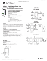
Single Pole/Unipolar/Unipolaire 3-Way/3 vías/3 voies
Screw Pressure Plate Back Wire
Cable trasero con tornillo y placa de presión
Fil arrière avec vis et plaque de pression
5. Install dimmer in wall box, with word “TOP” on the strap right side
up, using mounting screws provided.
6. Attach wall plate and then restore power to circuit.
NOTE: This device should be installed after sheet rocking and
painting are completed.
NOTE: It is normal for the dimmer to feel warm during operation. Use
a separate neutral wire for each phase of a multiphase system
containing a dimmer, and for high power single phase applications
where flickering is present.
MULTIPLE GANGING OF DIMMERS AND OTHER DEVICE
Any combination of dimmer models and other devices may be ganged
together. Break off tabs are provided on the 1000W dimmer straps for
multi-gang applications. Pry off the tabs using pliers before
installation, as shown in the figure. De-rate the maximum load
according to the following table:
P.O. Box 4822, Syracuse, NY 13221-4822
(800-223-4185)
www.passandseymour.com P/N 340798 Rev. B
GROUND WIRE
(Green or Bare)
Traveler wire to
3-Way Switch
Wire to Source
120VAC 60Hz
ALAMBRE DE TIERRA
(Verde o desnudo)
FIL DE TERRE (vert ou nu)
Alambre de la fuente
120 VCA 60Hz
Raccorder à la source
120 VCA 60 Hz
Traveler wire to
3-Way Switch
Alambre común al
interruptor de 3 vías
Commun vers
l’interrupteur 3 voies
Alambre común al
interruptor de 3 vías
Commun vers
l’interrupteur 3 voies
Remove all fins
Desprender todas
las lengüetas
Retirer toutes
les languettes
Remove inside fins only
Desprender solamente
las lengüetas internas
Ne retirer que
les languettes intérieures
Dimmer Maximum
Multi-Gang Derating
Catalog # Load 2 Gang Installation 3 Gang Installation
D703P 7000 W 700 W 700 W
D1103P 1100 W 1000 W 800 W
GROUND WIRE
(Green or Bare)
Wire to Light
120VAC 60Hz
Wire to Source
120VAC 60Hz
ALAMBRE DE TIERRA
(Verde o desnudo)
FIL DE TERRE (vert ou nu)
Alambre de la fuente
120 VCA 60Hz
Raccorder à la source
120 VCA 60 Hz
Do not wire
this terminal
No cablear esta terminal
Ne rien brancher sur
cette borne
Alambre
a la lámpara
120 VCA 60Hz
Raccorder à la lampe
120 VCA 60 Hz
Figure 1
Figura 1
Figure 1
Insert wire to bottom
of hole.
Introduzca el alambre
al hueco del fondo.
Insèrer le fil jusqu’au
fond du trou.
Securely tighten screw
to retain inserted wire.
Apriete firmemente el
tornillo para retener el
alambre insertado.
Bien serrer la vis pour
immobiliser le fil inséré.
Termination takes #12 or #14 AWG stranded or solid copper conductors.
El borne recibe conductores de cobre trenzados o sólidos de calibre #12 - #14 AWG
Utiliser des conducteurs en cuivre massifs ou torsadés de calibre 12 ou 14 AWG.
340798_HarmonyDim_IS_12160:12160_HarmonyDimmer IS 10/23/08 10:58 AM Page 2
/