
Operator’s Manual
International English (GB)
Form No. 3322-704
Dingo
322
Traction Unit
Model Number 22305TE—990001 & Up

The Toro Company – 1999
8111 Lyndale Ave. South
Bloomington, MN 55420–1196
All Rights Reserved
Printed in the USA
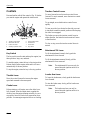
Introduction
Thank you for purchasing a Toro product.
All of us at Toro want you to be completely satisfied
with your new product, so feel free to contact your
local Authorized Service Dealer for help with service,
genuine replacement parts, or other information you
may require.
Whenever you contact your Authorized Service
Dealer or the factory, always know the model and
serial numbers of your product. These numbers will
help the Service Dealer or Service Representative
provide exact information about your specific
product. The two numbers are stamped into a plate
mounted on the left rear side of the frame.
For your convenience, write the product model and
serial numbers in the space below.
Model No:
Serial No.
Read this manual carefully to learn how to operate
and maintain your product correctly. Reading this
manual will help you and others avoid personal injury
and damage to the product. Although we design,
produce and market safe, state-of-the-art products,
you are responsible for using the product properly
and safely. You are also responsible for training
persons, who you allow to use the product, about safe
operation.
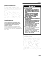
The warning system in this manual identifies
potential hazards and has special safety messages that
help you and others avoid personal injury, even death.
DANGER, WARNING and CAUTION are signal
words used to identify the level of hazard. However,
regardless of the hazard, be extremely careful.
DANGER signals an extreme hazard that will cause
serious injury or death if the recommended
precautions are not followed.
WARNING signals a hazard that may cause serious
injury or death if the recommended precautions are
not followed.
CAUTION signals a hazard that may cause minor or
moderate injury if the recommended precautions are
not followed.
Two other words are also used to highlight
information. “Important” calls attention to special
mechanical information and “Note” emphasizes
general information worthy of special attention.
The left and right side of the machine is determined
by standing on the platform in the normal operator’s
position.

1
Contents
Page
Safety 2.
. . . . . . . . . . . . . . . . . . . . . . . . . . . . . . . .
Safe Operating Practices 2
. . . . . . . . . . . . . .
Sound Pressure Level 4
. . . . . . . . . . . . . . . . .
Sound Power Level 5
. . . . . . . . . . . . . . . . . .
Vibration Level 5
. . . . . . . . . . . . . . . . . . . . .
Slope Chart 6
. . . . . . . . . . . . . . . . . . . . . . . . .
Safety and Instruction Decals 7
. . . . . . . . . .
Assembly 9
. . . . . . . . . . . . . . . . . . . . . . . . . . . . . .
Loose Parts 9
. . . . . . . . . . . . . . . . . . . . . . . . .
Installing the Valve Lever 9
. . . . . . . . . . . . .
Activating the Battery 9
. . . . . . . . . . . . . . . .
Specifications 12
. . . . . . . . . . . . . . . . . . . . . . . . . . .
Attachments 12
. . . . . . . . . . . . . . . . . . . . . . . .
Stability Data 13
. . . . . . . . . . . . . . . . . . . . . . .
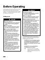
Before Operating 14
. . . . . . . . . . . . . . . . . . . . . . . .
Adding Fuel 14
. . . . . . . . . . . . . . . . . . . . . . . .
Checking the Oil Level 15
. . . . . . . . . . . . . . .
Removing Debris from the Traction Unit 15
.
Checking the Hydraulic Fluid 16
. . . . . . . . . .
Tire pressure 16
. . . . . . . . . . . . . . . . . . . . . . . .
Page
Operation 17
. . . . . . . . . . . . . . . . . . . . . . . . . . . . . .
Traction Unit Overview 17
. . . . . . . . . . . . . . .
Controls 18
. . . . . . . . . . . . . . . . . . . . . . . . . . .
Starting and Stopping the Engine 20
. . . . . . .
Driving Forward or Backward 21
. . . . . . . . . .
Stopping the Traction Unit 21
. . . . . . . . . . . . .
Moving a Non-functioning Traction Unit 22
.
Using the Cylinder Locks 22
. . . . . . . . . . . . .
Installing and Removing Attachments 23
. . . .
Securing the Traction Unit for Transport 24
. .
Maintenance 25
. . . . . . . . . . . . . . . . . . . . . . . . . . . .
Service Interval Chart 25
. . . . . . . . . . . . . . . .
Testing the Parking Brake 26
. . . . . . . . . . . . .
Removing/Installing the Hood 26
. . . . . . . . . .
Servicing the Air Cleaner 26
. . . . . . . . . . . . . .
Servicing the Engine Oil 28
. . . . . . . . . . . . . .
Servicing the Spark Plugs 29
. . . . . . . . . . . . .
Greasing the Traction Unit 30
. . . . . . . . . . . . .
Changing the Fuel Filter 31
. . . . . . . . . . . . . .
Draining the Fuel Tanks 32
. . . . . . . . . . . . . . .
Servicing the Hydraulic System 33
. . . . . . . . .
Servicing the Battery 34
. . . . . . . . . . . . . . . . .
Cleaning and Storage 35
. . . . . . . . . . . . . . . . .
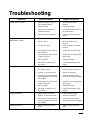
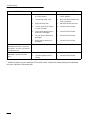
Troubleshooting 37
. . . . . . . . . . . . . . . . . . . . . . . . .

2
Safety
Improper use or maintenance by the operator or
owner can result in injury. To reduce the potential
for injury, comply with these safety instructions
and always pay attention to the safety alert
symbol, which means CAUTION, WARNING, or
DANGER—“personal safety instruction.” Failure
to comply with the instruction may result in
personal injury or death.
Safe
Operating Practices
This product is capable of amputating hands and feet.
Always follow all safety instructions to avoid serious
injury or death.
General Operation
• Read, understand, and follow all instructions in
the operator’s manual and on the traction unit
before starting. Also, read all attachment
manuals where supplied
• Allow only responsible adults who are familiar
with the instructions to operate the traction unit.
•
Always wear long pants and substantial shoes.
Wearing safety glasses, safety shoes, hearing
protection, and a hard hat are advisable and may
be required by some local ordinances and
insurance regulations.
• Ensure that the area is clear of other people
before operating the traction unit. Stop the
traction unit if anyone enters the area.
• Never carry passengers on attachments or on the
traction unit.
• Always look down and behind before and while
backing.
• Do not place your feet under the platform.
• Slow down before turning. Sharp turns on any
terrain may cause loss of control.
• Never leave a running traction unit unattended.
Always lower the loader arms, stop the engine,
and remove the key before dismounting.
• Do not exceed the rated operating capacity, as
the traction unit may become unstable which
may result in loss of control.
• Do not carry a load with the arms raised. Always
carry loads close to the ground. Do not step off
of the platform with the load raised.
• Do not over-load the attachment and always
keep the load level when raising the loader arms.
Logs, boards, and other items could roll down
the loader arms, injuring you.
• Never jerk the control levers; use a steady
motion.
• Keep your hands, feet, hair, and loose clothing
away from any moving parts.
• Operate only in daylight or good artificial light.
• Do not operate the traction unit while under the
influence of alcohol or drugs.
• Watch for traffic when operating near or crossing
roadways.
• Use extra care when loading or unloading the
traction unit onto a trailer or truck.
• Do not touch parts which may be hot from
operation. Allow them to cool before attempting
to maintain, adjust, or service.
Slope Operation
Slopes are a major factor related to loss-of-control
and tip-over accidents, which can result in severe
injury or death. All slopes require extra caution.

Safety
3
• Do not operate the traction unit on hillsides or
slopes exceeding the angles recommended in the
Stability Data section, page 13, and those in the
attachment operator’s manual. See also the
slope chart on page 6.
• Operate up and down slopes with the heavy
end of the traction unit uphill. Weight
distribution changes. An empty bucket will make
the rear of the traction unit the heavy end, and a
full bucket will make the front of the traction
unit the heavy end. Most other attachments will
make the front of traction unit the heavy end.
• Raising the loader arms on a slope will affect the
stability of the machine. Whenever possible,
keep the loader arms in the lowered position
when on slopes.
• Removing an attachment on a slope will make
the rear of the traction unit heavy. Refer to the
Stability Data section, page 13, to determine
whether the attachment can be safely removed
on the slope.
• Remove obstacles such as rocks, tree limbs, etc.
from the work area. Watch for holes, ruts, or
bumps, as uneven terrain could overturn the
traction unit. T
all grass can hide obstacles.
• Use slow speed on slopes. Before starting the
engine, put the pump selector lever in the slow
(turtle) position so that you will not have to stop
or shift while on the slope.
• Follow the recommendations in the attachment
manuals for the use of counterweights to
improve stability.
• Use only Toro approved attachments.
Attachments can change the stability and the
operating characteristics of the traction unit.
Warranty may be voided if used with
unapproved attachments.
• Keep all movements on slopes slow and gradual.
Do not make sudden changes in speed or
direction.
• Avoid starting or stopping on a slope. If tires
lose traction, proceed slowly, straight down the
slope.
• Check for overhead clearances (i.e. branches,
doorways, electrical wires) before driving under
any objects and do not contact them.
• Avoid turning on slopes. If you must turn, turn
slowly and keep the heavy end of the traction
unit uphill.
• Do not operate near drop-offs, ditches, or
embankments. The traction unit could suddenly
turn over if a wheel goes over the edge of a cliff
or ditch, or if an edge caves in.
• Do not operate on wet grass. Reduced traction
could cause sliding.
• Do not park the traction unit on a hillside or
slope without lowering the attachment to the
ground and chocking the wheels.
• Do not try to stabilize the traction unit by putting
your foot on the ground.
Children
Tragic accidents can occur if the operator is not alert
to the presence of children. Children are often
attracted to the traction unit and the work activity.
Never assume that children will remain where you
last saw them.
• Keep children out of the work area and under the
watchful care of another responsible adult.
• Be alert and turn the traction unit off if children
enter the area.
• Before and while backing, look behind and down
for small children.

Safety
4
• Never carry children. They may fall off and be
seriously injured or interfere with safe traction
unit operation.
• Never allow children to operate the traction unit.
• Use extra care when approaching blind corners,
shrubs, trees, the end of a fence, or other objects
that may obscure vision.
Service
• Stop the engine and disconnect the spark plug
wires before performing any service, repairs,
maintenance, or adjustments.
• If any maintenance or repair requires the loader
arms to be in the raised position, secure the arms
in the raised position with the hydraulic cylinder
locks included with traction unit.
• Never run a traction unit inside a closed area.
• Keep nuts and bolts tight. Keep equipment in
good condition.
• Never tamper with safety devices. Check safety
systems for proper operation before each use.
• Keep the traction unit free of grass, leaves, or
other debris build-up. Clean up oil or fuel
spillage. Allow the traction unit to cool before
storing.
• Use extra care when handling gasoline and other
fuels. They are flammable and vapors are
explosive.
• Use only an approved container.
• Never remove the gas cap or add fuel when
the engine is running. Allow the engine to
cool before refueling. Do not smoke.
• Never refuel the traction unit indoors.
• Never store the traction unit or fuel
container inside where there is an open
flame, such as near a water heater or
furnace.
• Never fill a container while it is inside a
vehicle, trunk, pick–up bed, or any surface
other than the ground; it could cause a static
discharge, igniting the fuel.
• Keep container nozzle in contact with the
tank during filling, to avoid static discharge.
• Stop and inspect the equipment if you strike an
object. Make any necessary repairs before
restarting.
• Use only genuine replacement parts to ensure
that original standards are maintained.
• Battery acid is poisonous and can cause burns.
Avoid contact with skin, eyes, and clothing.
Protect your face, eyes, and clothing when
working with a battery.
• Battery gases can explode. Keep cigarettes,
sparks and flames away from the battery.
• Keep your body and hands away from pin hole
leaks or nozzles that eject high pressure
hydraulic fluid. Use cardboard or paper to find
hydraulic leaks. Hydraulic fluid escaping under
pressure can penetrate skin and cause injury
requiring surgery within a few hours by a
qualified surgeon or gangrene may result.
Sound
Pressure Level
This unit has a sound pressure at the operator’s ear of
97 dB(A), based on measurements of identical
machines per Directive 81/1051/EEC.

Safety
5
Sound
Power Level
This unit has a sound power level of 105 LwA, based
on measurements of identical machines per Directive
84/538/EEC.
Vibration
Level
This unit has a maximum hand-arm vibration level of
0.8 m/s
2
and whole body vibration level of 0.1 m/s
2
based on measurements of identical machines per EN
1033 and EN 1032.

Safety
6
Slope
Chart

Safety
7
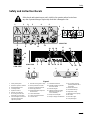
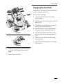
Safety and Instruction Decals
Safety decals and instructions are easily visible to the operator and are located near
any area of potential danger. Replace any decal that is damaged or lost.
# 100–1701
# 100–1702
# 100–1704
# 100–1706
# 99–3088
# 93–6686
1
8
7
6
1 3 4 5
2
9
10
12
11
13
21
18
19
26
27
2
2
28
1
321
D
C
R
F
19
29 30
24
1514
20
23
16
21 22
17
25
1 2
Figure 1
1. Safety
alert symbol
2.
Read the operator
’
s manual
3.
Entanglement hazard
4.
Crushing hazard
5.
Explosion hazard
6.
Electric shock hazard
7.
Do not dig in areas with
buried gas or power lines
8.
Shut of
f engine and remove
key before leaving the
operator’
s position
9. W
ait for moving parts to stop
10. W
ear protective foot wear
11. W
ear a protective hard hat
12. W
ear eye protection
13.
Keep bystanders away from
the work area
14.
Lower attachment
15.
Lever movement indicator
16. T
raction drive
17. T
ilt attachment down
18.
Shift the auxiliary hydraulics
lever into neutral
19.
Start the engine
20. T
ipping hazard–exceeding
rated load capacity can
cause instability
21.
Keep a full load uphill
22.
Keep an empty load downhill
23.
Do not step of
f of the
operator platform with a
raised load
24.
Raise attachment
25. T
ilt attachment up
26.
Hydraulic oil only
27.
Maximum load capacity
28.
No riders
29.
Run the engine
30.
Stop the engine

Safety
8
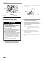
#
93–9084
# 100–1703
# 98–8235
# 93–9367
#
98–8219
#
94–2551
1
2
3
4
7
5
1
3
1
3
6
8
9
10
Figure 2
1. Fast
2. Traction
drive
3. Slow
4.
Pinch point–crushing of
fingers or hands
5.
Keep hands away
6.
Engine speed
7.
Lift/tie down point
8. Off
9. Choke
10. On

9
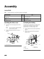
Assembly
Loose
Parts
Note: Use the chart below to verify that all parts have been shipped.
DESCRIPTION QTY. USE
T
raction Unit
V
alve Lever
1
1
Install valve lever
Key 2
Start engine
Hydraulic oil filter
1
Break-in oil change
Installing
the V
alve Lever
1. Thread the lever into the pump selector valve
(Fig. 3).
Note: The lever should be installed with the
bend toward the operator.
2. Tighten the jam nut on the lever to lock it in
position.
1
m–3883
Figure 3
1. Pump
selector lever
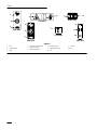
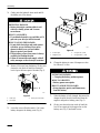
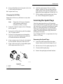
Activating
the Battery
The traction unit is shipped with a dry battery. Bulk
electrolyte with 1.260 specific gravity must be
purchased from a local battery supply outlet.
1. Remove the hood; refer to Removing the Hood,
page 26.
2. Remove the wing nuts and bar securing the
battery (Fig. 4).
3
5
1 m–4391
2
4
Figure 4
1. Battery
2. Bar
3. Positive
cable
4.
Rubber cover
5.
Negative cable

Assembly
10
3. Gently push the hydraulic hoses aside and lift
the battery out of the chassis.
POTENTIAL HAZARD
• Battery electrolyte contains sulfuric acid
which is a deadly poison and it causes
severe burns.
WHAT CAN HAPPEN
• If you drink electrolyte you could die or if it
gets onto your skin you will be burned.
HOW TO AV
OID THE HAZARD
• Do not drink electrolyte and avoid contact
with skin, eyes or clothing. Wear safety
glasses to shield your eyes and rubber
gloves to protect your hands.
• Fill the battery where clean water is always
available for flushing the skin.
• Follow all instructions and comply with all
safety messages on the electrolyte container.
4. Remove filler caps from the battery. Slowly pour
electrolyte into each cell until the electrolyte
level is up to the lower part of the tube (Fig. 5).
1
2
3
1262
Figure 5
1. Filler
caps
2. Electrolyte
3.
Lower part of the tube
5. Leave the covers off and connect a 3 to 4 amp
battery charger to the battery posts (Fig. 6).
4
1
2
3
1254
Figure 6
1. Positive
post
2.
Negative post
3.
Charger red (+) wire
4.
Charger black (–) wire
6. Charge the battery at a rate of 4 amperes or less
for 4 hours (12 volts).
POTENTIAL HAZARD
• Charging the battery pr
oduces gasses.
WHAT CAN HAPPEN
• Battery gasses can explode.
HOW TO AV
OID THE HAZARD
• Keep cigarettes, sparks, and flames away
from the battery.
7. When the battery is fully charged, disconnect the
charger from the electrical outlet and from the
negative and positive battery posts (Fig. 6).
8. Slowly pour electrolyte into each cell until the
level is once again up to the upper line on the
battery case (Fig. 5) and install covers.

Assembly
11
9. Install the battery into the chassis (Fig. 4).
10. Secure the battery in the chassis with the bar and
wing nuts removed previously (Fig. 4).
11. Using the bolt and wing nut supplied with the
battery, connect the positive (red) cable to the
positive (+) battery post (Fig. 4). Slide the
rubber cover over the battery post.
12. Using the bolt and wing nut supplied with the
battery, connect the negative (black) cable to the
negative (–) battery post (Fig. 4).
Note: Ensure that the battery cables do not
contact any sharp edges or each other.
13. Install the hood; refer to Installing the Hood,
page 26.

12
Specifications
Note: Specifications and design are subject to change without notice.
Width
40.5 inches (103 cm)
Length
60 inches (152 cm)
Height
49 inches (125 cm)
Weight
1522 lbs (690 Kg)
Operating capacity (with a 200 lb operator)
515 lbs (234 Kg)
T
ipping capacity (with a 200 lb operator)
1030 lbs (467 Kg)
Wheelbase
28 inches (71 cm)
Dump height (with standard bucket)
48.75 inches (124 cm)
Reach—fully raised (with the standard bucket)
26 inches (66 cm)
Height to hinge pin (with the standard bucket fully raised)
66 inches (168 cm)
Attachments
Many attachments are available for use with the
traction unit. These attachments allow you to to
perform many different functions with the traction
unit such as hauling materials, digging holes, grading,
and more. Contact your Toro dealer for a list of all
approved SiteW
ork Systems attachments and
accessories.
IMPORTANT: Use only Toro approved
attachments.

Check Before Operating
13
Stability
Data
The following table lists the maximum slope recommended for the traction unit in the positions listed in the
table. Slopes over the listed degree may cause the traction unit to become unstable. The data in the table
assumes that the loader arms are fully lowered and that the factory installed tires are on the traction unit, inflated
to the recommended pressure; raised arms and other tire types or pressure may affect the stability.
Maximum Recommended Slope
when Operating with:
Configuration
Front Uphill
Rear Uphill
Side Uphill
T
raction unit without attachment
10° 20° 13°
T
raction unit with counterweight, without attachment
8° 20° 9°
T
raction unit with an attachment rated with one of the following
stability ratings for each slope position:*
A 25° 25° 20°
B 20° 20° 17°
C 15° 15° 13°
D 10° 10° 9°
E 5° 5° 5°
* In each attachment manual is a set of three stability ratings, one for each hill position. To determine the
maximum slope you can traverse with the attachment installed, find the degree of slope that corresponds to the
stabilities ratings of the attachment.
Example: If the attachment installed on the traction unit has a Front Uphill rating of B, a Rear Uphill rating of
D, and a Side Uphill rating of C, then you could drive forward up a 20
° slope, rearward up a 10° slope, or
sideways on a 13° slope, as listed in the above table.

14
Before Operating
Before operating, check the fuel and oil level, remove
debris from the traction unit, and check the tire
pressure. Also, ensure that the area is clear of people
and debris. You should also know and have marked
the locations of all utility lines.
Adding
Fuel
POTENTIAL
HAZARD
• When fueling, under certain circumstances,
a static charge can develop, igniting the
gasoline.
WHAT CAN HAPPEN
• A fire or explosion from gasoline can burn
you, others, and cause property damage.
HOW TO AV
OID THE HAZARD
• Always place gasoline containers on the
ground away from your vehicle before
filling.
• Do not fill gasoline containers inside a
vehicle or on a truck or trailer bed because
interior carpets or plastic truck bed liners
may insulate the container and slow the
loss of any static charge.
• When practical, remove gas-powered
equipment from the truck or trailer and
refuel the equipment with its wheels on the
ground.
• If this is not possible, then refuel such
equipment on a truck or trailer from a
portable container, rather than from a
gasoline dispenser nozzle.
• If a gasoline dispenser nozzle must be used,
keep the nozzle in contact with the rim of
the fuel tank or container opening at all
times until fueling is complete.
POTENTIAL HAZARD
• In certain conditions gasoline is extremely
flammable and highly explosive.
WHAT CAN HAPPEN
• A fire or explosion from gasoline can burn
you, others, and cause property damage.
HOW TO AV
OID THE HAZARD
• Fill the fuel tank outdoors, in an open area,
when the engine is cold. Wipe up any
gasoline that spills.
• Do not fill the fuel tank completely full.
Add gasoline to the fuel tank until the level
is 1/4” to 1/2” (6 mm to 13 mm) below the
bottom of the filler neck. This empty space
in the tank allows gasoline to expand.
• Never smoke when handling gasoline, and
stay away from an open flame or where
gasoline fumes may be ignited by a spark.
• Store gasoline in an approved container
and keep it out of the reach of children.
Never buy more than a 30-day supply of
gasoline.
Use unleaded regular gasoline (85 pump octane
minimum). Leaded regular gasoline may be used if
unleaded regular is not available.
IMPORTANT: Never use methanol, gasoline
containing methanol, or gasohol containing
more than 10% ethanol because the fuel
system could be damaged. Do not mix oil with
gasoline.
IMPORTANT: Never use fuel additives
containing methanol or ethanol.
Note: The two fuel tanks will run empty
equally; however, you must fill them
separately because filling one will not
fill the other.

Check Before Operating
15
Filling the Fuel Tanks
1. Park the traction unit on a level surface, lower
the loader arms, and stop the engine.
2. Remove the key and allow the engine to cool.
3. Clean around the fuel tank caps and remove
them.
4. Use a funnel and add unleaded regular gasoline
to each fuel tank, until the level is 1/4 to 1/2 inch
(6 mm to 13 mm) below the bottom of each filler
neck.
IMPORTANT: This space in the tank allows
gasoline to expand. Do not fill the fuel tank
completely full.
5. Install the fuel tank caps securely. Wipe up any
gasoline that may have spilled.
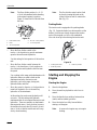
Checking
the Oil Level
1. Park the traction unit on a level surface, lower
the loader arms, and stop the engine.
2. Remove the key and allow the engine to cool.
3. Clean around the oil dipstick (Fig. 7).
4. Pull out the dipstick and wipe the metal end
clean (Fig. 7).
5. Slide the dipstick fully into the dipstick tube
(Fig. 7).
6. Pull the dipstick out and look at the metal end.
7. If the oil level is low, clean around the oil filler
cap and remove the cap (Fig. 7).
8. Slowly pour only enough oil into the valve cover
to raise the level to the F (full) mark.
IMPORTANT: If you overfill the crankcase
with oil, the excess oil will damage the engine.
9. Replace the filler cap and dipstick.
1
4
2
m–3873 m–3219
3
Figure 7
1. Oil
dipstick
2.
Filler cap
3. V
alve cover
4.
Metal end
Removing
Debris from the
T
raction Unit
IMPORTANT: Operating the engine with a
blocked grass scr
een, dirty or plugged cooling
fins, and/or cooling shrouds removed, will
result in engine damage from overheating.
1. Park the traction unit on a level surface, raise the
loader arms, and install the cylinder locks; refer
to Using the Cylinder Locks, page 22.
2. Stop the engine and remove the key.
3. Remove the hood; refer to Removing the Hood,
page 26.
4. Clean any debris from the grill before each use
and/or during use, if required.
5. Wipe away debris from the air cleaner before
each use and/or during use, if required.
6. Clean any debris build–up on the engine with a
brush or blower before each use.
IMPORTANT: It is preferable to blow dirt
out, rather than washing it out. If water is
used, keep it away from electrical items and
hydraulic valves. Do not use a high-pressure
washer. High-pressure washing can damage
the electrical system and hydraulic valves or
deplete grease.

Check Before Operating
16
7. Install the hood; refer to Installing the Hood,
page 26.
8. Remove and store the cylinder locks (refer to
Using the Cylinder Locks, page 22), and lower
the loader arms.
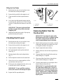
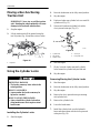
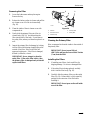
Checking
the Hydraulic Fluid
Check the hydraulic fluid level before the engine is
first started and after every 25 operating hours.
Hydraulic Tank Capacity: 17.25 gal. (67 l)
Use only Group 1 ISO type 46/68 anti–wear
hydraulic fluids, recommended for ambient
temperatures consistently below 100_F (38_C), such
as Toro Hy–Pro, Mobil Fluid 424, or other equivalent
fluid.
IMPORTANT: Use only the group 1 ISO type
46/68 anti–wear hydraulic fluids. Other fluids
could cause system damage.
1. Remove the attachment, if one is installed; refer
to Removing an Attachment, page 24.
2. Park the traction unit on a level surface, raise the
loader arms, and install the cylinder locks; refer
to Using the Cylinder Locks, page 22.
3. Stop the engine and remove the key.
4. Remove the hood; refer to Removing the Hood,
page 26.
5. Clean the area around the filler neck of the
hydraulic tank (Fig. 8).
6. Remove the cap from the filler neck and check
the fluid level on the dipstick (Fig. 8).
The fluid level should be 1/2 to 3/8 inches (10 to
15 mm) below the mark on the dipstick when the
loader arms are raised. If the loader arms are
lowered, the fluid level should be at the mark on
the dipstick.
1
m–4392
2
Figure 8
1. Filler
neck cap
2. Dipstick
7. If the level is low, add enough fluid to raise it to
the proper level.
8. Install the cap on the filler neck.
9. Install the hood; refer to Installing the Hood,
page 26.
10. Remove and store the cylinder locks (refer to
Using the Cylinder Locks, page 22) and lower
the loader arms.
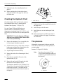
Tire
pressure
Maintain the air pressure in the tires as specified.
Check the tires when they are cold to get the most
accurate reading.
Pressure: 15–20 psi (103–138 kPa)
Note: Use a lower tire pressure (15 psi/
103 kPa) when operating in sandy soil
conditions to provide better traction in
the loose soil.
1
m–1872
Figure 9
1. Valve
stem

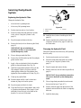
17
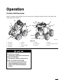
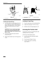
Operation
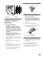
Traction
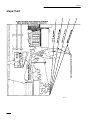
Unit Overview
Figure 10 contains a front and back view of the traction unit. Familiarize yourself with all of the traction unit
components listed in Figure 10.
m–4393/4389
5
1
3
2
6
7
8
9
10
11
12
11
3
4
13
14
Figure 10
1. Mount
plate
2. T
ilt cylinder
3.
Loader arms
4.
Lift cylinder
5.
Fuel tank
6. Wheel
7.
Operator platform
8. Engine
9.
Air filter
10.
Control panel
11.
Lift points
12. Handle
13.
Auxiliary hydraulic couplers
14. Hood
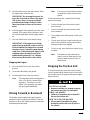
POTENTIAL
HAZARD
• The operator could fall off of the platform.
WHAT CAN HAPPEN
• The operator could be seriously injured.
HOW TO AV
OID THE HAZARD
• Do not move any of the contr
ol levers
unless standing with both feet on the
platform and with hands holding the
handles.

Operation
18
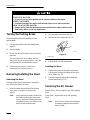
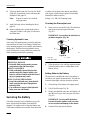
Controls
Become familiar with all the controls (Fig. 11) before
you start the engine and operate the traction unit.
m–4388
1
2
3
5
4
7
6
8
Figure 1
1
1. Traction
control levers
2.
Attachment tilt lever
3.
Loader arm lever
4.
Auxiliary hydraulics lever
5.
Speed selector lever
6.
Throttle lever
7.
Choke lever
8.
Key switch
Key Switch
The key switch, used to start and stop the engine, has
three positions: stop, run, and start.
To start the engine, rotate the key to the start position.
Release the key when engine starts and it will move
automatically to the run position.
To stop the engine, rotate the key to the stop position.
Throttle Lever
Move the control forward to increase the engine
speed and rearward to decrease speed.
Choke Lever
Before starting a cold engine, move the choke lever
fully forward. After the engine starts, regulate the
choke to keep the engine running smoothly. As soon
as possible, move the choke lever rearward as far as
possible. A warm engine requires little or no choking.
Traction Control Levers
To move forward, move the traction control levers
forward. To move rearward, move the traction control
levers rearward.
To go straight, move both traction control levers
equally.
To turn, move the lever located on the side you want
to turn back toward the neutral position while keeping
the other lever engaged.
The farther you move the traction control levers in
either direction, the faster the traction unit will move
in that direction.
To slow or stop, move the traction control levers to
neutral.
Attachment Tilt Lever
To tilt the attachment forward, slowly push the
attachment tilt lever forward.
To tilt the attachment rearward, slowly pull the
attachment tilt lever rearward.
Note: The attachment tilt lever can only be
moved when the ignition switch is in
the run position.
Loader Arm Lever
To lower the loader arms, slowly push the loader arm
lever forward.
To raise the loader arms, slowly pull the loader arm
lever rearward.
Note: The loader arm lever can only be
moved when the ignition switch is in
the run position.
Page is loading ...
Page is loading ...
Page is loading ...
Page is loading ...
Page is loading ...
Page is loading ...
Page is loading ...
Page is loading ...
Page is loading ...
Page is loading ...
Page is loading ...
Page is loading ...
Page is loading ...
Page is loading ...
Page is loading ...
Page is loading ...
Page is loading ...
Page is loading ...
Page is loading ...
Page is loading ...
-
 1
1
-
 2
2
-
 3
3
-
 4
4
-
 5
5
-
 6
6
-
 7
7
-
 8
8
-
 9
9
-
 10
10
-
 11
11
-
 12
12
-
 13
13
-
 14
14
-
 15
15
-
 16
16
-
 17
17
-
 18
18
-
 19
19
-
 20
20
-
 21
21
-
 22
22
-
 23
23
-
 24
24
-
 25
25
-
 26
26
-
 27
27
-
 28
28
-
 29
29
-
 30
30
-
 31
31
-
 32
32
-
 33
33
-
 34
34
-
 35
35
-
 36
36
-
 37
37
-
 38
38
-
 39
39
-
 40
40


Ask a question and I''ll find the answer in the document
Finding information in a document is now easier with AI
Related papers
-
Toro TX 420 Compact Utility Loader User manual
-
Toro Dingo 322 Traction Unit User manual
-
-
Toro 323 Compact Utility Loader User manual
-
Toro Dingo 320-D Compact Utility Loader User manual
-
-
-
-
-


