Trendnet RB-TEW-840APBO Quick Installation Guide

Category
Bridges & repeaters
Type
Quick Installation Guide

This manual is also suitable for

TEW-840APBO (V1)
Quick Installation Guide
Table of Contents
2. Hardware Setup and Configuration
3. Hardware Installation
1 English
1. Before You Start
1
1. Before You Start
Package Contents
Ÿ Proprietary/Passive PoE injector (24V DC, 0.6A)
Ÿ Mounting Hardware
Minimum Requirements
Ÿ Computer with a network port and web browser
Ÿ A network switch or router with an available network LAN port
Ÿ Additional TEW-840APBO H/W: v1.xR wireless AC867 directional access point
Ÿ 4 x RJ-45 network cables
Ÿ TEW-840APBO
Ÿ Quick Installation Guide
Note:
The TEW-840APBO does not support IEEE 802.3at/af PoE standards. You must use the
proprietary/passive power over Ethernet injector that is supplied with the TEW-840APBO. This
installation guide will walk you through the installation and configuration of two TEW-840APBO
access points to establish a wireless point to point bridge using WDS (wireless distribution
system). The RJ-45 Ethernet cable between the passive PoE injector and access point can have
a maximum length of up to 60 m (197 ft.).
ENGLISHFRANÇAIS
ESPAÑOL
2
2. Hardware Setup and Configuration
Phase 1: Overview
In this installation guide, we will assume the following:
The TEW-840APBO access points will be configured with the following settings:
Router Settings:
Router/Default Gateway IP address: 192.168.10.1
Subnet Mask: 255.255.255.0
TEW-840APBO #1
IP Address: 192.168.10.50
Netmask (Subnet Mask): 255.255.255.0
IP Gateway (Default Gateway): 192.168.10.1
Primary DNS: 192.168.10.1
Wireless Channel Default: 48
WDS Access Point Mode (CSMA)
WPA2-PSK Encryption
WDS Station Mode (CSMA)
TEW-840APBO #2
WPA2-PSK Encryption
IP Address: 192.168.10.51
Netmask (Subnet Mask): 255.255.255.0
IP Gateway (Default Gateway): 192.168.10.1
Primary DNS: 192.168.10.1
Wireless Channel Default: 48
Note:
Ÿ Configure and connect the access points before mounting.
Ÿ The initial configuration should be completed in a testing environment with two
TEW-840APBO access points approximately 15 ft. (5 m) apart from one another with the
front of the access points directly facing each other.
Ÿ The configuration example in this guide will use the default/standard TEW-840APBO channel
access mode CSMA. More details can be found in the user's guide about TDMA channel
access mode which is also supported by the TEW-840APBO wireless AP.
Ÿ The default IP address of the TEW-840APBO is 192.168.10.100. To configure the
TEW-840APBO, your network adapter must have an IP address within the 192.168.10.x
subnet (e.g. 192.168.10.10). Please refer to the Appendix in the User's Guide for more
information.
3
Phase 2: TEW-840APBO Unit #1 Hardware Setup and Configuration
1. Remove the cover of the access point by pulling and holding the bottom tab in the vertical
direction down (based on the access point orientation below) and sliding the cover below
away from the access point.
Pull and hold tab
ENGLISHFRANÇAIS
ESPAÑOL
4
2. Write down the SSID and WPA2 Key of the TEW-840APBO #1 access point. The SSID and
WPA2 Key can be found on the inside of the device cover where the Ethernet LAN ports are
located (shown below).
3. Using a network cable, connect one end of the cable to the LAN1 (PoE) port.
Model: TEW-840APBO /A
IP Address: 192.168.10.100
Subnet Mask: 255.255.255.0
User Name: admin
Password: admin
Mode: WDS AP
SSID: TRENDnet840_XXXX
WPA2 Key: 840XXXXXXXX
Default Channel: 48
Cable Guide
LAN2 LAN1 (PoE)
LAN2 LAN1 (PoE)
PWR LAN1 LAN2 WLAN
TEW-840APBO
FCC ID: XU8TEW840APBO
IC ID: 6337A-TEW840APBO
LAN2 LAN1 (PoE)
LAN2 LAN1 (PoE)
PWR LAN1 LAN2 WLAN
TEW-840APBO
FCC ID: XU8TEW840APBO
IC ID: 6337A-TEW840APBO
5
Included PoE injector
LAN1 (PoE)
PoE LAN
9. Assign a static IP address to your computer's network adapter in the subnet of
192.168.10.x (e.g. 192.168.10.10) and subnet mask of 255.255.255.0.
4. Connect the other end of the network cable to the PoE port on the included PoE injector.
5. Using another network cable, connect one end to the LAN port on the included PoE injector.
6. Connect the other end of the network cable to your computer's Ethernet port.
7. Attach the power cord to the PoE injector and plug the connected power cord into a power
outlet.
8. Confirm the device is powered on through the LED indicators.
10. Open your web browser and type the IP address of the access point in the address bar, then
press Enter. The default IP address is 192.168.10.100.
POWER
ENGLISHFRANÇAIS
ESPAÑOL
6
11. When prompted, login to the browser configuration page using the default user name and
password settings.
User Name: admin
Password: admin
Note: User Name and Password are case sensitive.
12. In the left hand menu under System Manager, click on Account.
13. Under Account Settings, change the default administrator password by typing in the
current password admin and your new password in the fields provided. Then click the
Apply button the save the new password settings. You will prompted to log back in with
the new password settings.
7
14. After setting a new administrator password, in the left hand menu under Network, click on
Basic.
15. In the IPv4 Settings section, enter the IP Address 192.168.10.50 and Subnet Mask
255.255.255.0, then click Save at the bottom of the page. When prompted to apply settings
at the bottom right of the page, click Apply to commit the changes.
Note: When configuring TEW-840APBO #2, enter the IP address settings 192.168.10.51 and
Netmask 255.255.255.0.
ENGLISHFRANÇAIS
ESPAÑOL
8
Phase 3: TEW-840APBO Unit #2 Hardware Setup and Configuration
When configuring the TEW-840APBO #2, repeat 1-14 of the steps in Phase 2 setup and
configuration.
1. In Step 15, under , enter the IP Address 192.168.10.51 and IPv4 Settings Subnet Mask
255.255.255.0, then click Save at the bottom of the page. When prompted to apply settings
at the bottom right of the page, click Apply to commit the changes.
2. In the left hand menu under Network, click Wireless.
3. Under 5GHz-802.11 AC/N, click the Operation Mode drop-down list and select WDS
Station.
9
4. Under Wireless Settings – 5GHz, click Edit.
5. Under Wireless Setting – 5GHz, next to Preferred BSSID, click Device Discovery. The device
will scan for wireless networks.
6. In the Site Survey list, select the SSID of the TEW-840APBO #1.
Note: This is the SSID of TEW-840APBO #1 from Phase 2 Step 2.
7. Under Wireless Security – 5GHz, in the Passphrase field, enter the WPA2 key of
TEW-840APBO #1 and click Save.
Note: This is the WPA2 key of TEW-840APBO #1 from Phase 2 Step 2.
8. After you are brought back to the main wireless settings page, click Save at the bottom of
the page. When prompted to apply settings at the bottom right of the page, click Apply to
commit the changes.
ENGLISHFRANÇAIS
ESPAÑOL
10
Phase 4: Confirm Connectivity
1. Leave your computer connected to TEW-840APBO #2 and keep the web management
interface open. In the left hand menu under Overview, click Connections and the
Connection Status should display Associated.
2. Make sure both TEW-840APBO #1 and TEW-840APBO #2 access points are powered on
approximately 15 ft. (5 m) apart from one another with front of access points directly facing
each other.
15 ft. (5m)
LAN1 (PoE)
PoE
LAN
TEW-840APBO #1 TEW-840APBO #2
LAN1 (PoE)
PoE
11
3. To further verify connectivity, in the TEW-840ABPO #2 web management interface under
Management, click on Tools.
4. Under Ping in the Target IP / Domain Name field, enter the IP address of TEW-840APBO #1,
192.168.10.50, then click Start.
5. Ping replies and 0% packet loss will indicate as successful point to point bridge connection
between the TEW-840APBO #1 and #2.
Note: If the connectivity test fails, wait for about a minute and try again. Make sure there are no
obstacles between the two access points when running the connectivity test and make sure the
two access points are not too close together.
ENGLISHFRANÇAIS
ESPAÑOL
12
3. Hardware Installation
1. Reinstall the cover by lining up the guide into the notch as shown and push until the cover
clips into place and is secured. The cover includes cable openings to route the connected
Ethernet cable(s) when installing.
2. Insert the included fasteners through the holes located at the back of the access point.
LAN2
LAN1 (PoE)
PWR
LAN1
LAN2
WLAN
TEW-840APBO
FCC ID: XU8TEW840APBO
IC ID: 6337A-TEW840APBO
13
3. Wrap the fasteners around the pole where the access points will be installed. On the
fasteners, insert the open end into the locking mechanism and pull tight until the access
point is secured.
4. After the access points are properly mounted, you can connect the RJ-45 cables from each
access point to your network.
Note: When set to WDS station mode, the TEW-840APBO features WiFi signal strength
connectivity LEDs located on the back of the access point to assist in determining the optimal
mounting position. (Red = Good, Orange = Better, Green = Best)
WLAN
LAN2
LAN1 (PoE)
PWR
LAN1
LAN2
WLAN
TEW-840APBO
FCC ID: XU8TEW840APBO
IC ID: 6337A-TEW840APBO
Red
Good
Orange
Better
Green
Best
ENGLISHFRANÇAIS
ESPAÑOL
14
Completed Installation Reference
Building 1 Building 2
Internet
Modem
Router
(ii) where applicable, antenna type(s), antenna models(s), and worst-case tilt angle(s) necessary to
remain compliant with the e.i.r.p. elevation mask requirement set forth in section 6.2.2.3 shall be clearly
indicated.
(ii) lorsqu'il y a lieu, les types d'antennes (s'il y en a plusieurs), les numéros de modèle de l'antenne et
les pires angles d'inclinaison nécessaires pour rester conforme à l'exigence de la p.i.r.e. applicable au
masque d'élévation, énoncée à la section 6.2.2.3, doivent être clairement indiqués.
Caution:
Le présent appareil est conforme aux CNR d' ISED applicables aux appareils radio exempts de licence.
L'exploitation est autorisée aux deux conditions suivantes : (1) le dispositif ne doit pas produire de
brouillage préjudiciable, et (2) ce dispositif doit accepter tout brouillage reçu, y compris un brouillage
susceptible de provoquer un fonctionnement indésirable.
(i) for devices with detachable antenna(s), the maximum antenna gain permitted for devices in the band
5725-5850 MHz shall be such that the equipment still complies with the e.i.r.p. limits as appropriate;
Avertissement:
Industry Canada statement:
This device complies with ISED's license-exempt RSSs. Operation is subject to the following two
conditions: (1) This device may not cause harmful interference, and (2) this device must accept any
interference received, including interference that may cause undesired operation.
(i) pour les dispositifs munis d'antennes amovibles, le gain maximal d'antenne permis (pour les
dispositifs utilisant la bande de 5 725 à 5 850 MHz) doit être conforme à la limite de la p.i.r.e. spécifiée,
selon le cas;
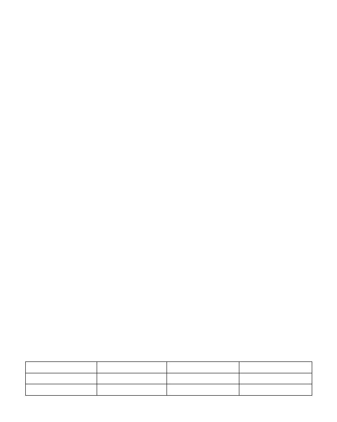
Type Gain Brand Manufacturer
Patch Antenna 13.35
SENAO NETWORKS SENAO NETWORKS
Patch Antenna 13.42 SENAO NETWORKS SENAO NETWORKS
Approved Antenna list
This equipment complies with ISED radiation exposure limits set forth for an uncontrolled environment.
This equipment should be installed and operated with greater than 25cm between the radiator & your
body.
Déclaration d'exposition aux radiations:
Cet équipement est conforme aux limites d'exposition aux rayonnements ISED établies pour un
environnement non contrôlé. Cet équipement doit être installé et utilisé à plus de 25cm entre le
radiateur et votre corps.
Radiation Exposure Statement:
1. Installation
2. Emplacement d'installation
3. Antenn externe.
Ce produit est destine a un usage specifique et doit etre installe par un personnel qualifie maitrisant les
radiofrequences et les regles s'y rapportant. L'installation et les reglages ne doivent pas etre modifies par
l'utilisateur final.
En usage normal, afin de respecter les exigences reglementaires concernant l'exposition aux
radiofrequences, ce produit doit etre installe de facon a respecter une distance de 25cm entre l'antenne
emettrice et les personnes.
Utiliser uniiquement les antennes approuvees par le fabricant. L'utilisation d'autres antennes peut conduire a
un niveau de rayonnement essentiel ou non essentiel depassant les niveaux limites definis par FCC/IC, ce qui
est interdit.
Instructions d'installation professionnelle
4. Procedure d'installation
Choisir avec soin la position d'installation et s'assurer que la puissance de sortie ne depasse pas les limites
en vigueur. La violation de cette regle peut conduire a de serieuses penalites federa.
Consulter le manuel d'utilisation.
5. Avertissement
Professional installation instruction
This product is designed for specific application and needs to be installed by a qualified personal who has RF
and related rule knowledge. The general user shall not attempt to install or change the setting.
4. Installation procedure
5. Warning
3. External antenna
Please refer to user's manual for the detail.
Please carefully select the installation position and make sure that the final output power does not exceed
the limit set force in relevant rules. The violation of the rule could lead to serious federal penalty.
1. Installation personal
2. Installation location
The product shall be installed at a location where the radiating antenna can be kept 25cm from nearby
person in normal operation condition to meet regulatory RF exposure requirement.
Use only the antennas which have been approved by the applicant. The non-approved antenna(s) may
produce unwanted spurious or excessive RF transmitting power which may lead to the violation of FCC/IC
limit and is prohibited.
  • Page 1 1
  • Page 2 2
  • Page 3 3
  • Page 4 4
  • Page 5 5
  • Page 6 6
  • Page 7 7
  • Page 8 8
  • Page 9 9
  • Page 10 10
  • Page 11 11
  • Page 12 12
  • Page 13 13
  • Page 14 14
  • Page 15 15
  • Page 16 16
  • Page 17 17
  • Page 18 18
  • Page 19 19
  • Page 20 20
  • Page 21 21

Trendnet RB-TEW-840APBO Quick Installation Guide

Category
Bridges & repeaters
Type
Quick Installation Guide
This manual is also suitable for

Ask a question and I''ll find the answer in the document

Finding information in a document is now easier with AI

in other languages