Progress Lighting P250002-009-30 Installation guide
- Category
- Household fans
- Type
- Installation guide

Ceiling Fan Installation Manual
P250002
93099665_A

Date Purchased
Store Purchased
Model No.
Serial No.
Vendor No.
UPC
109226
Limited Lifetime Warranty
Progress Lighting fan motors are warranted to the original purchaser to be free of electrical and/or mechanical defects for so
long as the original purchaser owns the fan. Pull chain switches, reverse switches, capacitors and metal finishes are warranted to
be free from defects in materials or workmanship for a period of 1 year from the date of purchase. Warping of wooden or plastic
blades is not covered by this warranty nor is corrosion and/or deterioration of any finishes for fans installed within ten miles of
any sea coast. Extended warranties for ENERGY STAR
®
qualified products may apply.
Progress Lighting ceiling fans with built-in LED light sources, when properly installed and under normal conditions of use, are
warranted to be free from defects in material and workmanship which cause the light sources to fail to operate in accordance
with the specifications for (i) five (5) years from the date of purchase on the LED Light modules and electrical components for
fans used in single family residences, and (ii) three (3) years from the date of purchase on the LED Light modules and electrical
components for fans used in multi-family or commercial applications. LED bulbs supplied by Progress Lighting carry no
warranty other than manufacturer’s warranty. Non-LED bulbs carry no warranty.
With proof of purchase, the original purchaser may return the defective fan to the place of purchase during the first 30 days for
replacement. After 30 days, the original purchaser MUST contact Progress Lighting at (864) 678-1000 for repair or replacement
which shall be determined in Progress Lighting’s sole discretion and shall be purchaser’s sole and exclusive remedy.
Labor and Shipping Excluded. This warranty does not cover any costs or fees associated with the labor (including, but not
limited to, electrician’s fees) required to install, remove, or replace a fan or any fan parts.
This warranty shall not apply to any loss or damage resulting from (i) normal wear and tear or alteration, misuse, abuse or
neglect, or (ii) improper installation, operation, repair or maintenance by original purchaser or a third party, including without
limitation improper voltage supply or power surge, use of improper parts or accessories, unauthorized repair (made or
attempted) or failure to provide maintenance to the fan.
THE FOREGOING WARRANTIES STATE PROGRESS LIGHTING’S ENTIRE WARRANTY OBLIGATION AND
ORIGINAL PURCHASER’S SOLE AND EXCLUSIVE REMEDY RELATED TO SUCH PRODUCTS. PROGRESS
LIGHTING IS NOT RESPONSIBLE FOR DAMAGES (INCLUDING INDIRECT, SPECIAL, INCIDENTIAL OR
CONSEQUENTIAL), DUE TO PRODUCT FAILURE, WHETHER ARISING OUT OF BREACH OF WARRANTY,
BREACH OF CONTRACT, OR OTHERWISE. THIS WARRANTY IS GIVEN IN LIEU OF ALL OTHER WARRANTIES,
WHETHER EXPRESSED OR IMPLIED, INCLUDING THOSE OF MERCHANTABILITY, FITNESS FOR A PARTICULAR
PURPOSE OR NONINFRINGEMENT.
Some states do not allow limitations on how long an implied warranty lasts or the exclusion or limitations of incidental or
consequential damages, so the above limitations and exclusions may not apply to you. This warranty gives you specific rights
and you may have other rights which vary from state to state.
785247000000
785247000000
785247000000

Table of Contents
Safety Rules.....................................................................................................................................................................................
Unpacking Your Fan .......................................................................................................................................................................
Installing Your Fan .........................................................................................................................................................................
Installing the Light Kit....................................................................................................................................................................
Installing the Fan without the Light Kit (optional) .......................................................................................................................
Operating Your Transmitter ..........................................................................................................................................................
Care of Your Fan ...........................................................................................................................................................................
Troubleshooting ............................................................................................................................................................................
Specifications ................................................................................................................................................................................
1.
2.
3.
9.
10.
12.
13.
14.
15.

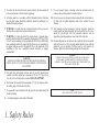
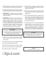
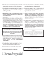
1. Safety Rules
1. To reduce the risk of electric shock, insure electricity has been turned off
at the circuit breaker or fuse box before beginning.
2. All wiring must be in accordance with the National Electrical Code and
local electrical codes. Electrical installation should be performed by a
qualified licensed electrician.
3. WARNING: To reduce the risk of electrical shock and fire, do not use
this fan with any solid-state fan speed control device.
4. WARNING: To reduce the risk of fire, electric shock, or personal injury,
mount to outlet box marked "Acceptable for Fan Support of 15.9 kg (35 lbs.)
Or Less" and use mounting screws provided with the outlet box. Most outlet
boxes commonly used for the support of light fixtures are not acceptable for
fan support and may need to be replaced. Due to the complexity of the
installation of this fan, a qualified licensed electrician is strongly
recommended.
WARNING
TO REDUCE THE RISK OF FIRE, ELECTRIC SHOCK OR PERSONAL
INJURY, MOUNT FAN TO OUTLET BOX MARKED ACCEPTABLE FOR
FAN SUPPORT.
5. The outlet box and support structure must be securely mounted and
capable of reliably supporting a minimum of 35 lbs (15.9 kg) or less.
Use only cUL-listed outlet boxes marked FOR FAN SUPPORT.
6. The fan must be mounted with a minimum of 7 ft (2.1m) clearance from
the trailing edge of the blades to the floor.
7. To operate the reverse function on this fan, press the reversing button while
the fan is running.
8. Avoid placing objects in the path of the blades.
9. To avoid personal injury or damage to the fan and other items, be
cautious when working around or cleaning the fan.
10. Do not use water or detergents when cleaning the fan or fan blades. A
dry dust cloth or lightly dampened cloth will be suitable for most
cleaning.
11. After making electrical connections, spliced conductors should be
turned upward and pushed carefully up into the outlet box. The wires
should be spread apart with the grounded conductor and the
equipment-grounding conductor on one side of the outlet box.
12. Electrical diagrams are for reference only. Light kits that are not packed
with the fan must be cUL Listed and marked suitable for use with the
model fan you are installing. Switches must be cUL General Use
Switches. Refer to the Instructions packaged with the light kits
NOTE
READ AND SAVE ALL INSTRUCTIONS!
WARNING
TO REDUCE THE RISK OF PERSONAL INJURY, DO NOT BEND THE
BLADE ARMS (ALSO REFERRED TO AS BRACKETS) DURING
ASSEMBLY OR AFTER INSTALLATION. DO NOT INSERT OBJECTS IN
THE PATH OF THE BLADES.

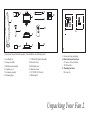
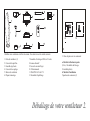
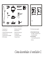
Unpack your fan and check the contents. You should have the following items:
Unpacking Your Fan 2.
1. Fan blades (3)
2. Canopy assembly
3. Ball/downrod assembly
4. Coupling cover
5. Fan motor assembly
6. Mounting plate
7. 18 Watt LED light kit assembly
8. Decorative ring
9. Metal light cover
10. Remote control
11. 12V MN21/A23 battery
12. Balancing kit
3
1
2
8
10
4
9
5
6
7
11
12
13. Loose parts bag containing:
a. Blade attachment hardware
(10 screws, 10 lock washers,
10 flat washers)
b. Mounting hardware
Wire nuts (3)
13
a
b

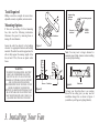
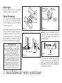
Tools Required
Phillips screw driver, straight slot screw driver,
adjustable wrench, step ladder, and wire cutters.
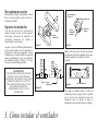
Mounting Options
If there isn't an existing cUL listed mounting
box, then read the following instructions.
Disconnect the power by removing fuses or
turning off circuit breakers.
Secure the outlet box directly to the building
structure. Use appropriate fasteners and building
materials. The outlet box and its support must be
able to fully support the moving weight of the
fan (at least 35 lbs). Do not use plastic outlet
boxes.
Figure 4
Figure 3
Figure 1
Figure 2
Outlet box
Outlet box
Outlet box
Note: You may need a longer downrod to
maintain proper blade clearance when installing
on a steep, sloped ceiling.
To hang your fan where there is an existing
fixture but no ceiling joist, you may need an
installation hanger bar as shown in Figure 4
(available at your Progress Lighting Retailer).
3. Installing Your Fan
WARNING
TO REDUCE THE RISK OF FIRE, ELECTRIC
SHOCK, OR OTHER PERSONAL INJURY,
MOUNT FAN ONLY TO AN OUTLET BOX
MARKED ACCEPTABLE FOR FAN SUPPORT
AND USE THE MOUNTING SCREWS
PROVIDED WITH THE OUTLET BOX. OUTLET
BOXES COMMONLY USED FOR THE
SUPPORT OF LIGHTING FIXTURES MAY NOT
BE ACCEPTABLE FOR FAN SUPPORT AND
MAY NEED TO BE REPLACED. CONSULT A
QUALIFIED ELECTRICIAN IF IN DOUBT.
Angled ceiling
maximum
20 angle
Recessed
outlet box
Provide strong support
Ceiling
hanger
bracket

4.
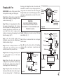
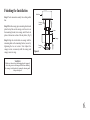
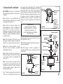
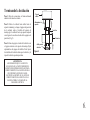
Hanging the Fan
REMEMBER to turn off the power. Follow
the steps below to hang your fan properly:
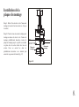
Step 1. Remove the decorative canopy bottom
cover from the canopy by turning the cover
counter clockwise.(Fig. 5)
Step 2. Remove the mounting bracket from
the canopy by removing the 1 of 2 screws
from the bottom of the mounting bracket and
loosening the other one a half turn from the
screw head. Next, turn the canopy counter
clockwise to removing the mounting bracket
from the canopy. (Fig. 5)
Step 3. Pass the 120-volt supply wires
through the center hole in the ceiling hanger
bracket as shown in Fig. 6.
Step 4. Secure the hanger bracket to the
ceiling outlet box with the screws and
washers provided with your outlet box.
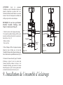
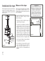
Step 5. Remove the hanger pin, lock pin and
set screws from the top of the motor
assembly. (Fig. 7)
Step 6. Route the safety cable and wires
exiting from the top of the fan motor through
the collar cover, canopy cover, canopy and
then through the ball / downrod. (Fig. 7)
Step 7. Align the holes at the bottom of the
downrod with the holes in the collar on top of
the motor housing (Fig. 7). Carefully insert
the hanger pin through the holes in the collar and
downrod. Be careful not to jam the pin against the
wiring inside the downrod. Insert the locking pin
through the hole near the end of the hanger pin until it
snaps into its locked position, as noted in the circle
inset of Fig. 7.
WARNING
FAILURE TO PROPERLY INSTALL
LOCKING PIN AS NOTED IN STEP 7
COULD RESULT IN FAN LOOSENING AND
POSSIBLY FALLING.
Figure 6
Figure 7
Ceiling
hanger
bracket
Mounting screws
(supplied with
electrical box)
CUL Listed
electrical
box
120V Wires
Washers
Supply wires
Safety cable
Downrod
Hanger pin
Lock pin
Set screws
Canopy
Canopy cover
Collar cover
Pin in locked
position
Step 8. Tighten two set screws on top of the fan
motor firmly. (Fig. 7)
Step 9. Place the downrod ball into the hanger
bracket socket.
Step 10. Secure the safety cable to the building
structure with a wood screw. (wood screw not
supplied)
Figure 5
Ceiling hanger
bracket
Ceiling
canopy
Canopy
cover

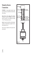
5.
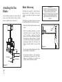
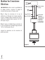
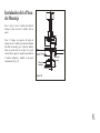
Make the Electric
Connections
WARNING: To avoid possible electrical shock,
be sure electricity is turned off at the main fuse box
before wiring.
Step 1. Motor to House Supply Wires Electrical
Connections: Connect the WHITE wire (Neutral)
from the outlet box to the WHITE wire marked
"AC in N" from the motor. (Fig. 8)
Step 2. Connect the BLACK wire (Hot) from the
outlet box to the BLACK wire marked "AC in L"
from the motor. (Fig. 8)
Secure all wire connections with the plastic wire
nuts provided.
Figure 8
Outlet Box
Black ("AC IN L")
White ("AC IN N")
White (Neutral)
Black (Hot)
Green or bare
copper (ground)
Ground (green)
(Connect to ground
wire on hanger
bracket if no house
ground wire exists.)

6.
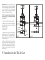
Finishing the Installation
Step 1. Tuck connections neatly into ceiling outlet
box.
Step 2. Slide the canopy up to mounting bracket and
place the key hole on the canopy over the screw on
the mounting bracket, turn canopy until it locks in
place at the narrow section of the key holes. (Fig. 9)
Step 3. Align the circular hole on canopy with the
remaining hole on the mounting bracket, secure by
tightening the two set screws. Note: Adjust the
canopy screws as necessary until the canopy and
canopy cover are snug.
WARNING
Make sure the notch on the hanging bracket properly
sits in the groove in the hanger ball before attaching
the canopy to the bracket by turning the housing until
it drops into place.
Outlet box
Canopy
cover
Canopy
Hanger
bracket
Figure 9
Screws

7.
Attaching the Fan
Blades
Fasten the blade assembly to the motor using the
screws, lock washers and flat washers provided.
Be sure to tighten all screws. (Figure 10)
Figure 10
Flat washer
Screws
Lock washer
Blade
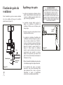
Blade Balancing
All blades are grouped by weight. Because
natural woods very in density, the fan may
wobble even though the blades are weighed
equally.
The following procedure should correct most
fan wobbling problems. Check after each step.
1. Check that all blade and blade arm screws are
secure.
2. Most fan wobbling problems are caused
when blade levels are unequal. Check this
level by selecting a point on the ceiling
above the tip of one of the blades. Measure
this distance as shown in Figure 11. Rotate
the fan until the next blade is positioned for
measurement. Repeat for each blade. The
distance deviation should be equal within
1/8".
3. Use the enclosed Blade Balancing Kit if the
blade wobble is still noticeable.
4. If the blade wobble is still noticeable,
interchanging two adjacent (side by side)
blades can redistribute the weight and
possibly result in smoother operation.
Touching
ceiling
Figure 11
WARNING
TO REDUCE THE RISK OF PERSONAL
INJURY, DO NOT BEND THE BLADE
HOLDERS WHILE INSTALLING,
BALANCING THE BLADES, OR CLEANING
THE FAN. DO NOT INSERT FOREIGN
OBJECTS BETWEEN ROTATING FAN
BLADES.

8.
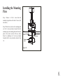
Installing the Mounting
Plate
Step 1. Remove 1 of the 3 screws from the
mounting ring and loosen the other 2 screws. (Do
not remove)
Step 2. Place the key holes on the mounting plate
over the 2 screws previously loosened from the
mounting ring, turn mounting plate until it locks in
place at the narrow section of the key holes.
Secure by tightening the 2 screws previously
loosened and the one previously removed. (Fig.
12)
Figure 12
Mounting
plate
Mounting ring
Screws

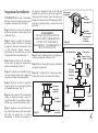
9.
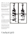
Installing the Light Kit
CAUTION: Before starting installation,
disconnect the power by turning off the circuit
breaker or removing the fuse at fuse box.
Turning power off using the fan switch is not
sufficient to prevent electric shock.
NOTE: If you do not wish to install the light
kit, skip steps 9 and proceed to step 10.
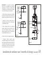
1. Remove the 2 screws from the mounting plate.
2. While holding the LED light kit under the fan
motor assembly, make the 2-pin wire connections:
(Fig. 13)
- White to white
- Black to blue
3. Place the LED light kit to the mounting plate.
Align the mounting holes with the holes in the
light kit and mounting plate, and fasten using the
two screws previously removed. (Fig. 13)
4. Slide the decorative ring up to light kit
assembly and place the key hole on the decorative
ring over the two screw on the light kit, turn
decorative ring until it locks in place at the narrow
section of the key holes. (Fig. 14)
Figure 13 Figure 14
Screws
Mounting
plate
Wire connector
LED Light kit
assembly
Screws
Decorative
ring

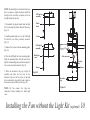
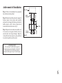
Installing the Fan without the Light Kit (optional)
10.
NOTE: The metal light cover included with your
fan is an option to replace the plastic shade for
the light in the event that you prefer not to use
the light feature of your fan.
1. Disassemble the plastic shade from the light
kit. You can keep the plastic shade for future use.
(Fig. 15)
2. Installing metal light cover to the LED light
kit with the two screws previously removed.
(Fig. 15)
3. Remove the 2 screws from the mounting plate.
(Fig. 16)
4. Place the LED light kit to the mounting plate.
Align the mounting holes with the holes in the
light kit and mounting plate, and fasten using the
two screws previously removed. (Fig. 16)
5. Slide the decorative ring up to light kit
assembly and place the key hole on the
decorative ring over the two screw on the light
kit, turn decorative ring until it locks in place at
the narrow section of the key holes. (Fig. 16)
NOTE: Do Not connect the 2-pin wire
connectores before installing the metal light
cover.
Figure 15
Figure 16
Screws
Plastic
shade
LED Light kit
assembly
Screws
Metal light
cover
LED Light kit
assembly
Screws
Decorative
ring
Mounting
plate
Wire connector

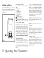
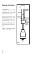
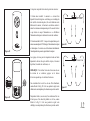
11. Operating Your Transmitter
Remote Control Button Definitions:
These six buttons are used to set the fan speed as
follows:
I = minimum speed
II = low speed
III = medium low speed
IV = medium speed
V = medium high speed
VI = high speed
button: Turns the fan off.
button: Controls fan direction.
button: Controls light. Switch the “D” and “ON” dip
switch on the back of transmitter to decide the light in
“ON/OFF” or “Dimmable” condition.
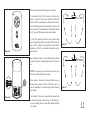
Your DC brushless motor is equipped with an
automatically learned type remote control. There are
no frequency switches on the receiver; the receiver
unit will automatically scan the frequency from the
remote control if any changes are made. The
frequency settings on the transmitter should be
changed ONLY in case of interference or if a
second or more ceiling fans with the same type of
control system are installed in the same structure.
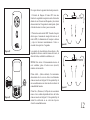
Setting the Remote Control
Follow the below steps to set the remote control:
The auto learning function will only mandate within
60 seconds when turning the fan’s AC power ON.
a) Select desired frequency from the transmitter.
The
dip switches can be set to 16 different combinations.
(Fig. 19)
b) From the back of the transmitter,
with the
fan’s power off, restore power to the fan. Press
and hold “SET” button for about 5 seconds and
release. If optional light kit is installed, the
light kit will flash twice and the signal light on
the hand held transmitter will come on when
the button is pressed. The fan has completed
the pairing process with the remote control and
is ready for use. (Fig. 19)
NOTE: If the self calibration test failed, turn the AC
power off; restore power and process the self
calibration test again.
NOTE: During self calibration test, the remote is
non-fuctional.
NOTE: The learning frequency function and self
calibration test will continue to retain the last set
frequency and calibration set even when the AC
power is shut off. If the frequency is changed the self
calibration test will occur again.
“D” and “ON” dip switch:
1. The “ON” selection is the light dimmable selection
and is to be used with all bulbs except for CFL bulbs.
The “D” selection is the light ON only (no dimming
function) and is to be used with CFL bulbs as CFL
bulbs in most cases cannot be used with dimming
controllers.
(Fig. 19)
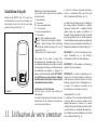
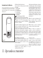
Installing the battery
Install a 12V MN21/A23 battery (included) into the
remote control. To prevent damage to the remote
control, remove the battery if not used for long
periods. (Fig. 17)
Figure 17
ON ECE
1234

This receiver provides the following protective function:
1. Lock Rotor Position: The DC motor has a built-in safety
against a stalled or locked rotor condition (stalled blade
rotation). If there is an obstruction or fault with the motor, the
current monitoring function will automatically turn power off
to the motor after 30 seconds. Remove the obstruction and turn
the AC power off. Restore power and re-start fan motor.
2. Over 80W protection: When the receiver detects motor
power consumption which is greater than 80W, the receiver
power will be stopped and operation will immediately
discontinue. Wait for 5 seconds and then turn the receiver
power back on.
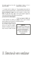
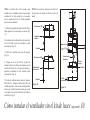
Speed settings for warm or cool weather depend on factors
such as the room size. Ceiling height, number of fans and so
on.
NOTE: To operate the reverse function on this fan, press
the reverse button while the fan is running.
Warm weather - (Forward) A downward airflow creates a
cooling effect as shown in Fig. 20. This allows you to set
your air conditioner on a warmer setting without affecting
your comfort.
Cool weather - (Reverse) An upward airflow moves warm
air off the ceiling area as shown in Fig. 21. This allows you
to set your heating unit on a cooler setting without affecting
your comfort.
Figure 20
Figure 21
12.
Figure 19
Figure 18
ON ECE
1234
ON ECE
1234

Here are some suggestions to help you maintain your
fan
1. Because of the fan's natural movement, some
connections may become loose.
Check the support
connections, brackets, and blade attachments
twice a year.
Make sure they are secure.
(It is not
necessary to remove fan from ceiling.)
2. Clean your fan periodically to help maintain its new
appearance over the years. Use only a soft brush or
lint-free cloth to avoid scratching the finish. The
plating is sealed with a lacquer to minimize
discoloration or tarnishing. Do not use water when
cleaning. This could damage the motor, or the wood,
or possibly cause an electrical shock.
3. You can apply a light coat of furniture polish to the
wood blades for additional protection and enhanced
beauty. Cover small scratches with a light application
of shoe polish.
4.
There is no need to oil your fan.
The motor has
permanently lubricated bearings.
IMPORTANT
MAKE SURE THE POWER IS OFF AT THE
ELECTRICAL PANEL BOX BEFORE YOU
ATTEMPT ANY REPAIRS. REFER TO THE
SECTION "MAKING ELECTRICAL
CONNECTIONS"
13.
Care of Your Fan

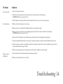
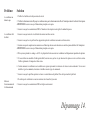
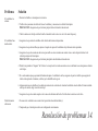
Troubleshooting
14.
Solution
1. Check circuit fuses or breakers.
2. Check line wire connections to the fan and switch wire connections in the switch housing.
CAUTION: Make sure main power is off.
3. Check to make sure the dip switches from the transmitter and receiver are set to the same frequency.
1. Make sure all motor housing screws are snug.
2. Make sure the screws that attach the fan blade bracket to the motor hub is tight.
3. Make sure wire nut connections are not rubbing against each other or the interior wall of the switch housing.
CAUTION: Make sure main power is off.
4. Allow a 24-hour "breaking-in" period. Most noise associated with a new fan disappear during this time.
5. If using an optional light kit, make sure the screws securing the glassware are tight. Check that light bulb is also secure.
6. Some fan motors are sensitive to signals from solid-state variable speed controls. If you have installed this type of control,
choose and install another type of control.
7. Make sure the upper canopy is a short distance from the ceiling. It should not touch the ceiling.
1. Do not connect the fan with wall mounted variable speed control (s).
2. Make sure the dip switches are set correctly.
Problem
Fan will not start.
Fan sounds noisy.
Remote control
malfunction

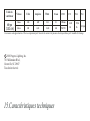
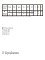
15.
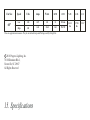
Specifications
2018 Progress Lighting, Inc.
701 Millennium Blvd.,
Greenville, SC 29607
All Rights Reserved
c
14.11
lbs
17.26
lbs
2.31'
Fan Size
Speed
Volts
Amps
Watts
RPM
CFM
N.W. G.W. C.F.
60"
Low
High
120
120
These are approximate measures. They do not include Amps and Wattage used by the light kit.
0.07
0.43
3.31
31.45
51
165
1954.66
7047.29

Manuel d’installation du ventilateur de plafond
P250002
ĊăĀĊĊććĆĤ

UPC
109226
Garantie limitée à vie
Progress Lighting garantit à l’acheteur initial que les moteurs de ventilateur sont exempts de défauts électriques ou mécaniques
tant que l’acheteur initial est propriétaire du ventilateur. Les interrupteurs à chaînette, les interrupteurs inverseurs, les
condensateurs et les finis métalliques sont garantis contre les défauts de matériaux ou de fabrication pendant une période d’un
an à partir de la date d’achat. Le gauchissement des pales de bois ou de plastique n’est pas couvert par la présente garantie, ni la
corrosion ou la détérioration du fini des ventilateurs installés à moins de dix milles d’un bord de mer. Les garanties prolongées
pour les produits homologués ENERGY STAR® peuvent s’appliquer.
Lorsqu’ils sont installés correctement et dans des conditions d’utilisation normales, les ventilateurs de plafond Progress
Lighting dotés d’une source lumineuse à DEL intégrée sont garantis contre les défauts de matériaux et de fabrication causant le
non fonctionnement de la source lumineuse selon les spécifications pendant (i) cinq (5) ans à partir de la date d’achat des
modules d’éclairage à DEL et des composants électriques des ventilateurs pour les résidences unifamiliales et (ii) trois (3) ans à
partir de la date d’achat des modules d’éclairage à DEL et des composants électriques des ventilateurs pour les résidences
multifamiliales et pour les utilisations commerciales. Les ampoules à DEL fournies par Progress Lighting ne sont assorties
d’aucune autre garantie que celle du fabricant. Les ampoules autres qu’à DEL ne sont assorties d’aucune garantie.
En fournissant la preuve d’achat, l’acheteur initial peut retourner le ventilateur défectueux à son lieu d’achat pendant les 30
premiers jours afin qu’il soit remplacé. Après 30 jours, l’acheteur initial DOIT communiquer avec Progress Lighting au 864
678-1000 pour la réparation ou le remplacement du ventilateur, ce qui sera déterminé exclusivement par Progress Lighting et
constituera le seul et unique recours de l’acheteur.
Main-d’œuvre et expédition exclus. La présente garantie ne couvre par les coûts et les frais associés à la main-d’œuvre (y
compris, sans s’y limiter, les frais d’électricien) nécessaires à l’installation, au retrait ou au remplacement du ventilateur ou des
pièces du ventilateur.
La présente garantie ne s’applique pas en cas de perte ou de dommage découlant (i) de l’usure normale, de l’altération ou d’un
usage incorrect, abusif ou négligent ou (ii) d’une installation, d’une utilisation, d’une réparation ou d’un entretien inadéquats par
l’acheteur initial ou un tiers, y compris, sans s’y limiter, une tension électrique inadéquate ou une surtension, l’utilisation de
pièces ou d’accessoires inadéquats, une réparation non autorisée (effectuée ou tentée) ou l’omission d’entretenir le ventilateur.
LES GARANTIES QUI PRÉCÈDENT ÉNONCENT L’ENTIÈRE RESPONSABILITÉ DE PROGRESS LIGHTING AU
CHAPITRE DE LA GARANTIE AINSI QUE LE SEUL ET UNIQUE RECOURS DE L’ACHETEUR LIÉ À CES PRODUITS.
PROGRESS LIGHTING N’EST PAS RESPONSABLE DES DOMMAGES (Y COMPRIS LES DOMMAGES INDIRECTS,
SPÉCIAUX, ACCESSOIRES OU CONSÉCUTIFS) ATTRIBUABLES À LA DÉFECTUOSITÉ DU PRODUIT, QU’ILS
SOIENT LIÉS À UNE VIOLATION DE LA GARANTIE, UNE VIOLATION DU CONTRAT OU AUTRE. LA PRÉSENTE
GARANTIE REMPLACE TOUTE AUTRE GARANTIE, EXPRESSE OU IMPLICITE, Y COMPRIS TOUTE GARANTIE
DE QUALITÉ MARCHANDE, D’UTILITÉ À UNE FIN PARTICULIÈRE OU D’ABSENCE DE CONTREFAÇON.
Certains États ne permettent pas de limitation à la durée implicite d’une garantie ou d’exclusion ou de limitation des dommages
accessoires ou consécutifs. Par conséquent, les limitations ci-dessus pourraient ne pas s’appliquer à vous. La présente garantie
vous accorde des droits précis et vous pourriez avoir d’autres droits qui peuvent varier d’un État à l’autre.
785247000000
785247000000
785247000000
Date d’achat
Magasin
Nº de modèle.
Nº de série .
Nº du fournisseur
Page is loading ...
Page is loading ...
Page is loading ...
Page is loading ...
Page is loading ...
Page is loading ...
Page is loading ...
Page is loading ...
Page is loading ...
Page is loading ...
Page is loading ...
Page is loading ...
Page is loading ...
Page is loading ...
Page is loading ...
Page is loading ...
Page is loading ...
Page is loading ...
Page is loading ...
Page is loading ...
Page is loading ...
Page is loading ...
Page is loading ...
Page is loading ...
Page is loading ...
Page is loading ...
Page is loading ...
Page is loading ...
Page is loading ...
Page is loading ...
Page is loading ...
Page is loading ...
Page is loading ...
Page is loading ...
-
 1
1
-
 2
2
-
 3
3
-
 4
4
-
 5
5
-
 6
6
-
 7
7
-
 8
8
-
 9
9
-
 10
10
-
 11
11
-
 12
12
-
 13
13
-
 14
14
-
 15
15
-
 16
16
-
 17
17
-
 18
18
-
 19
19
-
 20
20
-
 21
21
-
 22
22
-
 23
23
-
 24
24
-
 25
25
-
 26
26
-
 27
27
-
 28
28
-
 29
29
-
 30
30
-
 31
31
-
 32
32
-
 33
33
-
 34
34
-
 35
35
-
 36
36
-
 37
37
-
 38
38
-
 39
39
-
 40
40
-
 41
41
-
 42
42
-
 43
43
-
 44
44
-
 45
45
-
 46
46
-
 47
47
-
 48
48
-
 49
49
-
 50
50
-
 51
51
-
 52
52
-
 53
53
-
 54
54


Progress Lighting P250002-009-30 Installation guide
- Category
- Household fans
- Type
- Installation guide
Ask a question and I''ll find the answer in the document
Finding information in a document is now easier with AI
in other languages
Related papers
-
Progress Lighting 93099665 D Installation guide
-
-
-
-
-
Progress Lighting P250000-129 User manual
-
-
-
-
Other documents
-
 urban ambiance UHP9053 Installation guide
-
 urban ambiance UHP9052 Installation guide
-
 urban ambiance UHP9051 Installation guide
-
 urban ambiance UHP9050 Installation guide
-
 urban ambiance UHP9091 Installation guide
-
 urban ambiance UHP9160 Installation guide
-
Savoy 52-417-3WA-13 Owner's manual
-
 urban ambiance UHP9291 Installation guide
-
 urban ambiance UHP9290 Installation guide
-
 urban ambiance UHP9281 Installation guide


