Ecor-Pro EPD200-PRO User manual
- Category
- Space heaters
- Type
- User manual
Page is loading ...

2
For safety reasons, read this information carefully before operating.
Persons who are not familiar with this type of product must not use it.
The dehumidier is safe, however, as with other electrical appliance, use it with care.
The installation must be in accordance with the regulations
of the country where the unit is used.
The unit is designated for indoor operation.
This appliance must be earthed and should only be
connected to an earthed 120 V – 60 Hz mains supply.
+
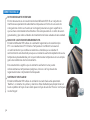
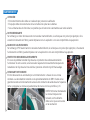
Thank you for choosing this innovative dehumidier.
This manual describes the many benets and advanced features that this unique product has to oer.
This dehumidier is a tough, industrial unit designed to be used almost anywhere that dry air is required.
Desiccant/Absorption dehumidiers are especially suited to applications where low relative humidities are
needed and work well over a wide temperature range.
We specialize in complete indoor humidity control. Our world class products incorporate the latest
technological developments and are designed to create a quality environment.
It is important that you read these instructions carefully before installing and using your new dehumidier.
Please keep them in a safe place for future reference.
THANK YOU! |
SAFETY |

3
US
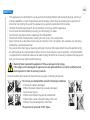
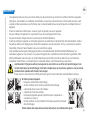
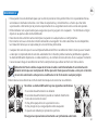
• This appliance is not intended for use by persons (including children) with reduced physical, sensory or
mental capabilities, or lack of experience and knowledge, unless they have been given supervision or
instruction concerning the use of the appliance by a person responsible for their safety.
• Children should be supervised to ensure that they do not play with the appliance.
• Do not clean the dehumidier by spraying it or immersing it in water.
• Do not insert any object into the opening of the dehumidier.
• Disconnect from the mains before cleaning the unit or any of its components.
• Never connect to an electrical outlet using an extension cord. If an outlet is not available, one should be
installed by a licensed electrician.
• Any service other than regular cleaning, setting fan mode or lter replacement should be performed by
an authorized service representative. Failure to do so could result in a loss of warranty. Your dehumidier
is supplied with an electrical cable and an earthed plug. Should it be necessary to replace this plug at any
time, you must use an earthed electrical plug.
Warning! Never operate this appliance if it has a damaged cord or plug.
If the supply cord is damaged an approved service representative or a similar qualied person
must replace it in order to avoid any hazards.
There should be direct access to the electrical plug after connecting the power!
Do not use your dehumidier under the following conditions:
• If the power cable is damaged
• Where the power cable may be easily damaged
• Close to heat source
• Where small children may be left unattended
• Where there is a risk of liquids falling on the unit
• Where it may be damaged by chemicals
This product is not made for DIY repair.
SAFETY (2) |

4
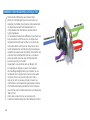
HOW IT WORKS EPD150/EPD150-PRO |
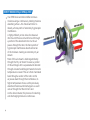
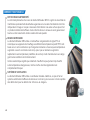
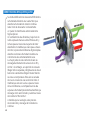
Your EPD Desiccant dehumidier removes
moisture using a continuously rotating moisture
absorbing wheel —this ‘Desiccant Rotor’ is
literally a honeycomb of extremely hygroscopic
membranes.
A highly ecient yet low noise fan draws air
into the unit (Process Air) and forces it through
a portion of the absorbent rotor. As the air
passes through the rotor, the honeycomb of
hygroscopic membranes absorb almost all
of the moisture creating an extremely dry air
stream.
Most of this air stream is discharged directly
through the ‘Dry Air Outlet’ however, a portion
of this air (Regen Air) is separated and directed
through a heater bank (Regen Heater) where it’s
temperature is raised. This air is then channeled
back through a section of the rotor. As this
air passes back through the membranes, its
higher temperature drives-out the previously
absorbed moisture and discharges it as warm
wet air through the ‘Wet Air Out’ duct.
As the wheel rotates, this process of collecting
and discharging moisture is continuous.

5
US
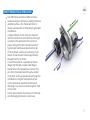
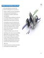
HOW IT WORKS EPD200/EPD200-PRO |
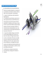
Your EDP Desiccant dehumidier removes
moisture using a continuously rotating moisture
absorbing wheel —this ‘Desiccant Rotor’ is
literally a honeycomb of extremely hygroscopic
membranes.
A highly ecient yet low noise fan draws air
into the unit (Process Air) and forces it through
a portion of the absorbent rotor. As the air
passes through the rotor, the honeycomb of
hygroscopic membranes absorb almost all
of the moisture creating an extremely dry air
stream; this air stream is discharged directly
through the ‘Dry Air Outlet’.
A second fan pushes a separate air stream
(Regen Air) through a heater bank (Regen
Heater) where it’s temperature is raised. This
air is then channeled back through a section
of the rotor. As this air passes back through the
membranes, its higher temperature drives-
out the previously absorbed moisture and
discharges it as warm wet air through the ‘Wet
Air Out’ duct.
As the wheel rotates, this process of collecting
and discharging moisture is continuous.

6
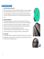
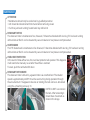
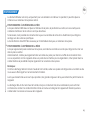
PATENTED DESICCANT ROTOR
The Desiccant Rotor is the heart of the EPD dehumidier. It is an array of specially
absorbent membranes arranged as a series of corrugations (as shown in the
cut-away image) to give a vast surface area making it an extremely ecient. It is
encased in a galvanized steel ring and turns on high quality sealed ball bearing
units.
REGEN HEATER BANK
The EPD dehumidier uses a ceramic PTC type regen heater. PTC (Positive
Temperature Coecient) heaters are based on a semi-conductor that changes
resistance as it becomes hotter. The semi-conductor is designed so that it’s
resistance rises rapidly at a predesignated temperature, thus it maintains this
temperature across a wide range of operational conditions.
This characteristic means that the heating element can never over heat to
hazardous temperatures, even if the regen airow is completely blocked.
FAN SYSTEM
The EPD dehumidier uses a patented "RadiCal" backward curved fan unit, this is a
highly eective yet quiet system. It is designed to give a good balance of airows
for both ‘Process’ and ‘Regen’ airows.
HOW IT WORKS WORKS (2) |

7
US
The EPD dehumidier is designed only for indoor use however, it can be placed inside or outside the room to
be dried.
INTERNAL POSITIONING
When positioning the unit inside the room, place it centrally, ensuring inlet and outlet ducts are clear of
obstruction.
If required, ducts can be connected to the outlet and/or inlet to direct the drying to specic areas.
The Wet-Air-Out MUST be ducted outside the room
EXTERNAL POSITIONING
When positioning the unit outside the room, connect ducting to the outlet to direct the dry air stream into the
room to be dried.
Optionally, the inlet may also be ducted to the room to give a re-circulation eect. In this case however,
because the unit uses a portion for the inlet air for regeneration, provision must be made in the inlet duct to
also draw air form outside the room.
Note:
As the Wet-Air-Out discharge is warm and very humid ensure it is directed where it will have no adverse
eect on the immediate environment.
All ducting lengths should be kept to a minimum —longer lengths will reduce performance.
The Wet-Air-Out is warm and very humid, when a duct is attached, condensation may form on the inside of
the duct. This duct should slope downwards away may from the unit to prevent any condensation running
back into the unit.
POSITIONING |

8
STAND-ALONE OPERATION
Connect the unit to suitable mains supply.
Ensure Remote Humidistat switch is set in the ‘OFF’ (O) position.
Switch Power switch to the ‘ON’ (I) position.
The fan will start and the Ammeter reading will rise. The ammeter indicates the current taken by the PTC
heater bank. Its reading will depend on the ‘Process’ air temperature and the ‘Regen’ airow. Typically, it will
indicate between 2 and 3 amps (EPD150/EPD150-PRO) or between 4 and 6 amps (EPD200/EPD200-PRO), this
will reduce if the airow is low or the ‘Process’ air temperature is high.
REMOTE OPERATION
For remote operation it is necessary to connect a switch or humidistat via the ‘Remote Humidistat Connector’
which can be accessed by removing the dust cap. A connection plug is available on request.
ATTENTION: The remote connector is mains voltage!
The remote switch/humidistat should be connected between pins 1 and 3.
The earth pin is connected to ground and can be used if required (see wiring diagram).
The Remote Humidistat switch should be set to the ‘ON’ position.
The unit will now operate according to the state of the remote switch.
AIR FILTER
The unit has an inlet air lter, this should be checked periodically and if necessary cleaned. It can be cleaned
with a vacuum cleaner or washed in mild detergent.
ATTENTION:
Do not run the unit without a lter tted as dust will impair the performance of the Desiccant Rotor.
OPERATION |

9
US
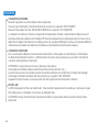
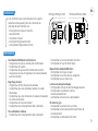
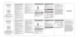
CONTROLS |
The controls are positioned on the front of the
unit next to the air outlet, they are:
• Power Switch
• Ammeter
• Hour Meter
• Remote Humidistat Switch
• Remote Humidistat Connector
EPD150 EPD150-PRO
EPD200 EPD200-PRO
If the dehumidier does not operate:
• Make sure the unit is plugged in.
• Check the fuse
• Check the remote humidistat setting
• Ensure the humidistat (if tted) is turned on
Low Airow:
• Check inlet air lter
• Check inlet/outlets not obstructed
• Check ductwork (if tted) is not obstructed
• Check voltage level
• Check fan is working
If the unit is noisy:
• Check fan operation
• Check rotor drive
• Check for loose screws
Low Dehumidifying Eect:
• Check airows
• Check Amps reading
• Check rotor is turning
Low Amps Reading:
• Check Regen airow
• Check Over-Heat Protector
• Check Heater bank
Rotor Not Turning
• Check belt tension
• Check drive-motor operation
• Check rotor alignment
TROUBLESHOOTING |
OFF
ON
REMOTE HUMIDISTAT
OFF
ON
POWER
A
10
5
A
O
I
O
I
OFF
ON
OFF
ON
POWER
Remote
Humidistat

10
MAINTENANCE |
ATTENTION
• Maintenance should only be carried out by qualied personnel
• Unit should be disconnected from mains before removing covers
• If unit has just been running, heater bank may still be hot
DESICCANT ROTOR
The desiccant rotor is maintenance free, however, if it becomes blocked with dust (e.g. if it has been running
without inlet air lter) it can be cleaned by vacuum cleaner or low pressure compressed air.
HEATER BANK
The PTC heater bank is maintenance free however, if it becomes blocked with dust (e.g. if it has been running
without inlet air lter) it can be cleaned by vacuum cleaner or low pressure compressed air.
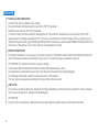
OVER-HEAT PROTECTOR
In the event of total airow loss, the over-heat protector will operate. If this happens
it will need to be manually re-set after the airow is restored.
To reset, push the red button (R) down.
DESICCANT ROTOR DRIVE
The desiccant rotor is driven by a geared motor via a toothed belt. The rotation
speed is approximately 20 RPH. It can be seen turning during operation through
the air outlet duct. If it appears to be slow or sticking, the belt can be re-tensioned
using the 4 mounting screws @ ‘‘A’’.
NOTE: Do NOT over-tension
the belt. After tensioning it
should have movement as
shown in the image.

11
US
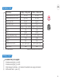
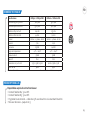
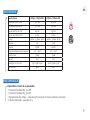
Specifications EPD150 / EPD150-PRO EPD200 / EPD200-PRO
Typical extraction @ 90
o
F 90% RH 74 L/ day 95 L/ day
Typical extraction @ 80
o
F 60% RH 53 L/ day 74 L/ day
Airflow (Dry Air Out) 224 cfm 235 cfm
Airflow (Wet Air Out) 44 cfm 74 cfm
Mains 120Vac ~ 1 phase • 60 Hz 120Vac ~ 1 phase • 60 Hz
Current 7.1A 11.7A
Power 850W 1400W
Operating temperature range -4
o
F — 104
o
F -4
o
F — 104
o
F
Noise level 56dB 58dB
IP rating IPx2 IPx2
Dimensions l x w x h inch 17.52 x 13.86 x 13.28 24.80 x 13.86 x 13.28
Weight net lbs 38.60 45.20
TECHNICAL DATA |
Subject to modications without prior notice.RH = relative humidity
Design
Great British
Available from your supplier
• Flexible ducting Ø 4", 9 or 18 ft
• Flexible ducting Ø 5", 9 or 18 ft
• High voltage humidistat – 15 ft cable mil standard screw plug connected
• Reticulated foam – pack of 3
OPTIONAL PARTS |

12
1
3
2
TERMINAL
BLOCK
MAINS
SWITCH
REMOTE
HUMIDISTAT
SWITCH
HOUR
METER
AMMETER
REMOTE
CONNECTOR
HEATER
BANK
CAPACITOR
OHP
ROTOR
DRIVE
BLU
BLK
BRN
G/Y
MAINS LEAD
L
N
E
WHT
WHT
WHT
E
M M
MAINS
SWITCH
REMOTE
HUMIDISTAT
SWITCH
REMOTE
CONNECTOR
REMOTE SWITCH /
HUMIDISTAT
(OPTIONAL)
OVER-HEAT
PROTECTOR
(MANUAL RESET)
HEATER
BANK
ROTOR DRIVERFAN
FAN
CAPACITOR
HOUR
METER
AMMETER
L
N
E
1
3
E
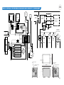
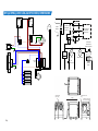
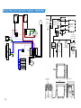
EPD150/EPD150-PRO WIRING DIAGRAM AND SCHEMATIC, DIMENSIONS |
PROCESS AIR
DUCT Ø 5˝
WET AIR OUTLET
DUCT Ø 3˝
OUTLET DUCT
Ø 5˝
13.86˝
13.28˝
17.52˝

13
US
1
3
2
TERMINAL
BLOCK
MAINS
LEAD
MAINS
SWITCH
REMOTE
HUMIDISTAT
SWITCH
HOUR
METER
AMMETER
REMOTE
CONNECTOR
E
HEATER
BANK
PROCESS
FAN
CAPACITOR
L
N
E
OHP
ROTOR
DRIVE
BLU
BLK
BRN
G/Y
REGEN
FAN
CAPACITOR
BLU
BLK
BRN
G/Y
REGEN FAN
PROCESS FAN
REMOTE
CONNECTOR
L
MAIN
SWITCH
N
M
PROCESS
FAN
ROTOR
DRIVER
HEATER
BANK
REMOTE
HUMIDISTAT
SWITCH
1
3
REMOTE SWITCH /
HUMIDISTAT
(OPTIONAL)
FAN
CAPACITOR
OVERHEAT
PROTECTION
(MANUAL RESET)
HOUR
METER
E
E
REGEN
FAN
AMMETER
FAN
CAPACITOR
MM
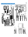
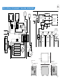
EPD200/EPD200-PRO WIRING DIAGRAM AND SCHEMATIC, DIMENSIONS |
OUTLET DUCT
Ø 5˝
REGEN AIR INLET
DUCT Ø 3˝
PROCESS AIR
DUCT Ø 5˝
WET AIR OUTLET
DUCT Ø 3˝
13.86˝
13.58˝
24.80˝
Page is loading ...
Page is loading ...
Page is loading ...
Page is loading ...
Page is loading ...
Page is loading ...
Page is loading ...
Page is loading ...
Page is loading ...
Page is loading ...

24
1
3
2
TERMINAL
BLOCK
MAINS
SWITCH
REMOTE
HUMIDISTAT
SWITCH
HOUR
METER
AMMETER
REMOTE
CONNECTOR
HEATER
BANK
CAPACITOR
OHP
ROTOR
DRIVE
BLU
BLK
BRN
G/Y
MAINS LEAD
L
N
E
WHT
WHT
WHT
E
M M
MAINS
SWITCH
REMOTE
HUMIDISTAT
SWITCH
REMOTE
CONNECTOR
REMOTE SWITCH /
HUMIDISTAT
(OPTIONAL)
OVER-HEAT
PROTECTOR
(MANUAL RESET)
HEATER
BANK
ROTOR DRIVERFAN
FAN
CAPACITOR
HOUR
METER
AMMETER
L
N
E
1
3
E
EPD150/EPD150-PRO CÂBLAGE ET SCHÉMA, DIMENSIONS |
conduite de l'air
Ø 5˝
conduite de sortie
de l'air humide Ø 3˝
conduite de
sortie Ø 5˝
13.86˝
13.28˝
17.52˝

25
FR
1
3
2
TERMINAL
BLOCK
MAINS
LEAD
MAINS
SWITCH
REMOTE
HUMIDISTAT
SWITCH
HOUR
METER
AMMETER
REMOTE
CONNECTOR
E
HEATER
BANK
PROCESS
FAN
CAPACITOR
L
N
E
OHP
ROTOR
DRIVE
BLU
BLK
BRN
G/Y
REGEN
FAN
CAPACITOR
BLU
BLK
BRN
G/Y
REGEN FAN
PROCESS FAN
REMOTE
CONNECTOR
L
MAIN
SWITCH
N
M
PROCESS
FAN
ROTOR
DRIVER
HEATER
BANK
REMOTE
HUMIDISTAT
SWITCH
1
3
REMOTE SWITCH /
HUMIDISTAT
(OPTIONAL)
FAN
CAPACITOR
OVERHEAT
PROTECTION
(MANUAL RESET)
HOUR
METER
E
E
REGEN
FAN
AMMETER
FAN
CAPACITOR
MM
EPD200/EPD200-PRO CÂBLAGE ET SCHÉMA, DIMENSIONS |
OUTLET DUCT
Ø 5˝
REGEN AIR INLET
DUCT Ø 3˝
PROCESS AIR
DUCT Ø 5˝
WET AIR OUTLET
DUCT Ø 3˝
13.86˝
13.58˝
24.80˝

26
Por razones de seguridad, lea detenidamente esta información antes de operar.
Las personas que no están familiarizadas con este tipo de producto no deben usarlo.
El deshumidicador es seguro, sin embargo, cómo cualquier otro aparato eléctrico, utilícelo con precaución.
La instalación debe estar acuerdo con los reglamentos del
país donde será utilizado.
Este aparato es designado para funcionamiento en interiores.
Este aparato solamente debería estar conectado a
120 V / 60 Hz de suministro eléctrico con una toma tierra.
+
Thank you for choosing this innovative dehumidier.
This manual describes the many benets and advanced features that this unique product has to oer.
This dehumidier is a tough, industrial unit designed to be used almost anywhere that dry air is required.
Desiccant/Absorption dehumidiers are especially suited to applications where low relative humidities are
needed and work well over a wide temperature range.
We specialize in complete indoor humidity control. Our world class products incorporate the latest
technological developments and are designed to create a quality environment.
It is important that you read these instructions carefully before installing and using your new dehumidier.
Please keep them in a safe place for future reference.
¡GRACIAS! |
SEGURIDAD |
Page is loading ...
Page is loading ...
Page is loading ...
Page is loading ...
Page is loading ...
Page is loading ...
Page is loading ...
Page is loading ...
Page is loading ...

36
1
3
2
TERMINAL
BLOCK
MAINS
SWITCH
REMOTE
HUMIDISTAT
SWITCH
HOUR
METER
AMMETER
REMOTE
CONNECTOR
HEATER
BANK
CAPACITOR
OHP
ROTOR
DRIVE
BLU
BLK
BRN
G/Y
MAINS LEAD
L
N
E
WHT
WHT
WHT
E
M M
MAINS
SWITCH
REMOTE
HUMIDISTAT
SWITCH
REMOTE
CONNECTOR
REMOTE SWITCH /
HUMIDISTAT
(OPTIONAL)
OVER-HEAT
PROTECTOR
(MANUAL RESET)
HEATER
BANK
ROTOR DRIVERFAN
FAN
CAPACITOR
HOUR
METER
AMMETER
L
N
E
1
3
E
EPD150/EPD150-PRO CABLEADO Y DIAGRAMA, DIMENSIONES |
conduite de l'air
Ø 5˝
conduite de sortie
de l'air humide Ø 3˝
conduite de
sortie Ø 5˝
13.86˝
13.28˝
17.52˝

37
ES
1
3
2
TERMINAL
BLOCK
MAINS
LEAD
MAINS
SWITCH
REMOTE
HUMIDISTAT
SWITCH
HOUR
METER
AMMETER
REMOTE
CONNECTOR
E
HEATER
BANK
PROCESS
FAN
CAPACITOR
L
N
E
OHP
ROTOR
DRIVE
BLU
BLK
BRN
G/Y
REGEN
FAN
CAPACITOR
BLU
BLK
BRN
G/Y
REGEN FAN
PROCESS FAN
REMOTE
CONNECTOR
L
MAIN
SWITCH
N
M
PROCESS
FAN
ROTOR
DRIVER
HEATER
BANK
REMOTE
HUMIDISTAT
SWITCH
1
3
REMOTE SWITCH /
HUMIDISTAT
(OPTIONAL)
FAN
CAPACITOR
OVERHEAT
PROTECTION
(MANUAL RESET)
HOUR
METER
E
E
REGEN
FAN
AMMETER
FAN
CAPACITOR
MM
EPD200/EPD200-PRO CABLEADO Y DIAGRAMA, DIMENSIONES |
OUTLET DUCT
Ø 5˝
REGEN AIR INLET
DUCT Ø 3˝
PROCESS AIR
DUCT Ø 5˝
WET AIR OUTLET
DUCT Ø 3˝
13.86˝
13.58˝
24.80˝
Page is loading ...
Page is loading ...

Subject to modications • Sous réserve de modications • Sujeto a modicaciones.
ECOR PRO USA, LLC
2292 Faraday Avenue
Suite 100
Carlsbad
CA 92008
# 760-248-3010
info@ecorprousa.com
www.ecorproducts.com
PM-dec.-19
-
 1
1
-
 2
2
-
 3
3
-
 4
4
-
 5
5
-
 6
6
-
 7
7
-
 8
8
-
 9
9
-
 10
10
-
 11
11
-
 12
12
-
 13
13
-
 14
14
-
 15
15
-
 16
16
-
 17
17
-
 18
18
-
 19
19
-
 20
20
-
 21
21
-
 22
22
-
 23
23
-
 24
24
-
 25
25
-
 26
26
-
 27
27
-
 28
28
-
 29
29
-
 30
30
-
 31
31
-
 32
32
-
 33
33
-
 34
34
-
 35
35
-
 36
36
-
 37
37
-
 38
38
-
 39
39
-
 40
40


Ecor-Pro EPD200-PRO User manual
- Category
- Space heaters
- Type
- User manual
Ask a question and I''ll find the answer in the document
Finding information in a document is now easier with AI
in other languages
- français: Ecor-Pro EPD200-PRO Manuel utilisateur
- español: Ecor-Pro EPD200-PRO Manual de usuario
Related papers
Other documents
-
Abestorm Guardian SN90 User manual
-
Sansui HDLCD2650 Datasheet
-
TRIANGLE TUBE Smart 316 User manual
-
-
Ecor Pro EPD30 User manual
-
 Dehutech 2400 User manual
-
Meaco DD8L Zambezi User manual
-
Honeywell CO301PC User manual
-
-
 Geek Heat HA31-05E User manual

