Kikusui PWR801H User manual

Type
User manual
400W model
PWR401L PWR401MH
PWR401ML PWR401H
800W model
PWR801L PWR801MH
PWR801ML PWR801H
1200W model
PWR1201L PWR1201MH
PWR1201ML PWR1201H
Communication Interface Manual
Regurated DC Power Supply PWR-01 Series
PART NO. IB031623
Apr. 2018
Communication Interface Manual Regurated DC Power Supply PWR-01 Series
KIKUSUI ELECTRONICS CORP.
http://www.kikusui.co.jp/en
1-1-3 Higashiyamata, Tsuzuki-ku, Yokohama,
224-0023, Japan
Tel: +81-45-482-6353 Fax: +81-45-482-6261
Website
Command List
KIKUSUI Electronics Corp. PWR-01 Interface Manual
*CLS
Clears all event registers including the status byte, event status, and error queue.
*ESE
Sets the event status enable register that is counted by the event summary bit (ESB) of the
status byte.
*ESR
Queries the event status register.
*IDN
Queries the model name, serial number, and rmware version of the PWR-01.
*LRN
Queries the command that can restore the current panel settings.
*OPC
Sets the OPC bit (bit 0) of the event status register when all the commands in standby have
been completed.
*OPT
Queries the option that are installed in the PWR-01.
*PSC
Sets whether to clear the event status enable register and the service request enable
register when the POWER switch is turned on (power-on status).
*RST
Resets the panel settings.
*SRE
Sets the service request enable register.
*STB
Queries the contents of the status byte register and the MSS (master summary status)
message.
*TRG
Trigger command.
Command List
*TST
Executes a self-test.
*WAI
Prevents the PWR-01 from executing subsequent commands until all operations in standby
are complete.
ABOR
Aborts operations such as change and execute sequence in all sequence groups.
ABOR:PROG
Aborts the sequence trigger function.
ABOR:TRAN
Aborts the setting change trigger function.
DISP:BRIG
Adjusts the screen brightness.
GLOB:*RST
Resets the panel settings (see *RST) of all the channels in the same multichannel domain.
GLOB:*TRG
Trigger command for all the channels in the same multichannel domain.
GLOB:ABOR
Aborts modifications and sequence execution on all trigger subsystems (TRANsient/
PROGram) of all the channels in the same multichannel domain.
GLOB:CURR
Sets the current of all the channels in the same multichannel domain.
GLOB:INIT:PROG
Starts the sequence trigger function of all the channels in the same multichannel domain.
GLOB:INIT:TRAN
Starts the setting change (TRANsient) trigger function of all the channels in the same
multichannel domain.
GLOB:OUTP
Turns the output on and off of all the channels in the same multichannel domain.
GLOB:OUTP:PROT:CLE
Clears alarms of all the channels in the same multichannel domain.
Command List
KIKUSUI Electronics Corp. PWR-01 Interface Manual
GLOB:VOLT
Sets the voltagee of all the channels in the same multichannel domain.
INIT:PROG
Starts the sequence trigger function.
INIT:TRAN
Starts the setting change (TRANsient) trigger function.
INST
Species the channel to congure.
INST:CAT
Queries the list of channels that can be congured with the INST command.
INST:INFO
Queries the information of the channel currently being controlled.
FETC:ALL/ MEAS:ALL
Queries the current and voltage.
FETC:CURR/ MEAS:CURR
Queries the measured value of the current.
FETC:VOLT/ MEAS:VOLT
Queries the measured value of the voltage.
MEM:REC
Recalls the voltage, current, OVP, UVL, and OCP values saved in the preset memory.
MEM:REC:PREV
Queries the settings that are stored in the preset memory.
MEM:SAVE
Saves the present voltage, current, OVP, UVL, and OCP values in the preset memory.
OUTP
Turns the output on and off.
OUTP:DEL:ON
Sets the output-on delay.
OUTP:DEL:OFF
Sets the output-off delay.
OUTP:EXT
This is an old style command.
OUTP:EXT:ADV
Sets whether output will be turned on and off externally.
OUTP:EXT:LOG
Sets the logic used to control the turning of output on and off using an external contact.
OUTP:PON
Sets the output state at power-on.
OUTP:PROT:CLE
Clears alarms.
OUTP:PROT:WDOG
Sets the Communication monitor timer.
OUTP:TRIG:STAT
Sets whether to output a trigger signal when the output is turned on.
PROG:CRE
Deletes the existing program and creates a new program.
PROG:LOOP
Changes the number of times that the program will repeat.
PROG:REM:LOOP
Queries the number of repetitions remaining in the sequence that is running.
PROG:REM:TIME
Queries the time remaining in the sequence that is running.
PROG:STEPS
Queries the number of program steps.
PROG:STEPS:LOOP:ADD
Sets the starting step and ending step of an interval loop to execute in the program and the
number of interval loops.
PROG:STEPS:LOOP:LIST
Queries all interval loops set in the program.
PROG:STEP<n>:CURR/ PROG:STEP_T:CURR
Sets the current and transition to use in the step.
Command List
KIKUSUI Electronics Corp. PWR-01 Interface Manual
PROG:STEP<n>:DWEL/ PROG:STEP_T:DWEL
Sets the step execution time.
PROG:STEP<n>:TRIGIN/ PROG:STEP_T:TRIGIN
Sets the step’s trigger signal input.
PROG:STEP<n>:TRIGOUT/ PROG:STEP_T:TRIGOUT
Sets the step’s trigger signal output.
PROG:STEP<n>:VOLT/ PROG:STEP_T:VOLT
Sets the voltage and transition to use in the step.
PROG:UCOD
Sets the user code to identify sequences.
CURR
Sets the current.
CURR:EXT:RANG
Sets the CC and CV control range that is used during external control.
CURR:EXT:SOUR
Sets whether constant current will be controlled externally.
CURR:LIM:AUTO
Enables or disables the limit on the current setting.
CURR:PROT
Sets the overcurrent protection (OCP) value.
CURR:PROT:DEL
Sets the detection time of OCP activation.
CURR:SST:FALL
Sets the soft stop time when the output is turned off.
CURR:SST:RISE
Sets the soft start time when the output is turned on.
CURR:TRIG
Sets the current value that is applied when a trigger is sent.
RES
Sets the internal resistance.
VOLT
Sets the voltage.
VOLT:EXT:RANG
Sets the CC and CV control range that is used during external control.
VOLT:EXT:SOUR
Sets whether constant voltage will be controlled externally.
VOLT:LIM:AUTO
Set whether to limit the voltage setting so that it does not exceed the OVP setting or
become lower than the UVP setting.
VOLT:LIM:LOW
Sets the undervoltage limit (UVL) trip point.
VOLT:PROT
Sets the overvoltage protection (OVP).
VOLT:SST:FALL
Sets the soft stop time when the output is turned off.
VOLT:SST:RISE
Sets the soft start time when the output is turned on.
VOLT:TRIG
Sets the voltage that is applied when a trigger is sent.
STAT:OPER
Queries the event of the OPERation status register.
STAT:OPER:COND
Queries the condition of the OPERation status register.
STAT:OPER:ENAB
Sets the enable register of the OPERation status register.
STAT:OPER:NTR
Sets the negative transition of the OPERation status register.
STAT:OPER:PTR
Sets the positive transition of the OPERation status register.
STAT:OPER:INST
Queries the event of the OPERation:INSTrument subregister.
Command List
KIKUSUI Electronics Corp. PWR-01 Interface Manual
STAT:OPER:INST:COND
Queries the condition of the OPERation:INSTrument subregister.
STAT:OPER:INST:ENAB
Sets the enable register of the OPERation:INSTrument subregister.
STAT:OPER:INST:NTR
Sets the negative transition of the OPERation:INSTrument subregister.
STAT:OPER:INST:PTR
Sets the positive transition of the OPERation:INSTrument subregister.
STAT:OPER:INST:ISUM<n>
Queries the event of the OPERation:INSTrument:ISUMmary<n> subregister.
STAT:OPER:INST:ISUM<n>:COND
Queries the condition of the OPERation:INSTrument:ISUMmary<n> subregister.
STAT:OPER:INST:ISUM<n>:ENAB
Sets the enable register of the OPERation:INSTrument:ISUMmary<n> subregister.
STAT:OPER:INST:ISUM<n>:NTR
Sets the negative transition of the OPERation:INSTrument:ISUMmary<n> subregister.
STAT:OPER:INST:ISUM<n>:PTR
Sets the positive transition of the OPERation:INSTrument:ISUMmary<n> subregister.
STAT:QUES
Queries the event of the QUEStionable status register.
STAT:QUES:COND
Queries the condition of the QUEStionable status register.
STAT:QUES:ENAB
Sets the enable register of the QUEStionable status register.
STAT:QUES:NTR
Sets the negative transition of the QUEStionable status register.
STAT:QUES:PTR
Sets the positive transition of the QUEStionable status register.
STAT:QUES:INST
Queries the event of the QUEStionable:INSTrument subregister.
STAT:QUES:INST:COND
Queries the condition of the QUEStionable:INSTrument subregister.
STAT:QUES:INST:ENAB
Sets the enable register of the QUEStionable:INSTrument subregister.
STAT:QUES:INST:NTR
Sets the negative transition of the QUEStionable:INSTrument subregister.
STAT:QUES:INST:PTR
Sets the positive transition of the QUEStionable:INSTrument subregister.
STAT:QUES:INST:ISUM<n>
Queries the event of the QUEStionable:INSTrument:ISUMmary<n> subregister.
STAT:QUES:INST:ISUM<n>:COND
Queries the condition of the QUEStionable:INSTrument:ISUMmary<n> subregister.
STAT:QUES:INST:ISUM<n>:ENAB
Sets the enable register of the QUEStionable:INSTrument:ISUMmary<n> subregister.
STAT:QUES:INST:ISUM<n>:NTR
Sets the negative transition of the QUEStionable:INSTrument:ISUMmary<n> subregister.
STAT:QUES:INST:ISUM<n>:PTR
Sets the positive transition of the QUEStionable:INSTrument:ISUMmary<n> subregister.
STAT:PRES
Resets the ENABle, PTRansition, and NTRansition filter registers of all status registers
(including sub registers) to their default values. 32 bits registers are used by the
multichannel function.
SYST:BEEP:STAT
Turns the buzzer on and off.
SYST:COMM:RLST
Sets the operation of the PWR-01 to local or remote.
SYST:CONF:BLE
Sets the bleeder circuit operation.
SYST:CONF:MAST
Queries the number of units in master-slave parallel operation.
Command List
KIKUSUI Electronics Corp. PWR-01 Interface Manual
SYST:CONF:MON:RANG
Sets the range for monitoring the voltage or current externally.
SYST:CONF:PROT:REC
Sets the output state when a low AC input protection (AC-FAIL) is released.
SYST:CONF:SC1/ SYST:CONF:SC2/ SYST:CONF:SC3
Registers the CONFIG setting item to the panel’s SC key.
SYST:CONF:SLAV:AMM
Sets whether or not the current or power on slave units is displayed on the panel during
master-slave parallel operation.
SYST:CONF:STAR:PRI
Sets the operation mode to be prioritized when the output is turned on.
SYST:ERR
Reads the oldest error information or event information from the error queue. The error
queue can store up to 16 errors.
-> Tutorial “Error Checking”
SYST:ERR:COUN
Returns the number of unread errors in the error queue.
SYST:ERR:TRAC
Sets whether to display communication errors by performing a debug trace.
SYST:EXT:STATOUT:CC:POL
Sets the polarity of the status output signal for constant-current mode.
SYST:EXT:STATOUT:CV:POL
Sets the polarity of the status output signal for constant-voltage mode.
SYST:EXT:STATOUT:OUTP:POL
Sets the polarity of the status output signal for output.
SYST:EXT:STATOUT:PROT:POL
Sets the polarity of the status output signal for protection operation.
SYST:EXT:TRIGIN:POL
Sets the polarity of the trigger signal input.
SYST:EXT:TRIGOUT:POL
Sets the polarity of the trigger signal output.
SYST:KLOC
Sets and releases the panel operation lock (keylock).
SYST:LOC/ SYST:REM/ SYST:RWL
This is an old style command.
SYST:SEC:IMM
Sanitizes all contents stored in memory and initializes the panel settings to their factory
default conditions.
SYST:VERS
Queries the version of the SCPI specications to which the PWR-01 conforms.
TRIG:PROG
Executes a software trigger for the PROGram trigger subsystem.
TRIG:PROG:EXEC
Queries the sequence states (execution state, present repetition count, present step
number, elapsed time, estimated time).
TRIG:PROG:SOUR
Sets the condition (trigger source) that determines when the PROGram trigger subsystem
actually executes a sequence operation after the PWR-01 receives the INIT:PROG
command.
TRIG:TRAN
Executes a software trigger for the TRANsient trigger subsystem.
TRIG:TRAN:SOUR
Sets the condition (trigger source) that determines when the TRANsient trigger subsystem
actually changing the setting after the PWR-01 receives the INIT:TRAN command.
Introduction
KIKUSUI Electronics Corp. PWR-01 Interface Manual
Introduction
The PWR-01 series Communication Interface Manual explains the settings and
commands for remotely controlling the PWR-01 series.
RS232C interface
USB interface
LAN interface
When the PWR-01 series is operating under remote control, the RMT LED on the
display on the front panel lights. To switch from remote mode to local mode from
the panel, press LOCAL.
For the safety precautions, installation, operation, and specications of the PWR-
01, read the accompanying PWR-01 series User's Manual.
Reading environment
This manual is in PDF format. The manual can be viewed by the following environ-
ment.
PDF Reader: Adobe Reader
Intended readers
This manual is written for readers with sufcient basic knowledge of how to control
instruments using a PC.
Familiarize yourself with the syntax of the SCPI commands that are used with the
product before you use them.
Structure of the manual
This manual consists of the following sections.
Overview
Setup
Overview of messages
Command
Appendix
Tutorial
Trademarks
Microsoft and Windows are registered trademarks of Microsoft Corporation in the
United States and/or other countries.
All other company names and product names used in this manual are trademarks
or registered trademarks of the respective company.
Firmware version of the product to which this manual applies
This manual applies to products with the following rmware version:
Ver.1.1x
Interface Setup
KIKUSUI Electronics Corp. PWR-01 Interface Manual
Instrument Interface Standards
The PWR-01 conforms to the following standards.
IEEE Std 488.2-1992 IEEE Standard Codes, Formats, Protocols, and Common
Commands For Use With IEEE Std 488.1-1987
IEEE Std 488.1-1987 IEEE Standard Digital Interface for Programmable Instru-
mentation
Standard Commands for Programmable Instruments (SCPI) version 1999.0
Universal Serial Bus Specication Rev 2.0
Universal Serial Bus Test and Measurement Class Specication (USBTMC) Rev
1.0
Universal Serial Bus Test and Measurement Class, Subclass USB488 Specica-
tion (USBTMC-USB488) Rev 1.0
TCP/IP Instrument Protcol Specication VXI-11 Rev 1.0 1995
TCP/IP-IEEE488.2 Interface Specication VXI-11.3 Draft 0.3 1995
LXI Device Specication 2011 rev 1.4
LXI HiSLIP Extended Function Rev 1.01
IVI-6.1 IVI High-Speed LAN Instrument Protocol (HiSLIP) Rev 1.0
VPP-4.3 The VISA Library 2015 Rev 5.5
Copyright and publication
The contents of this manual may not be reproduced, in whole or in part, without the
prior consent of the copyright holder.
The specications of this product and the contents of this manual are subject to
change without prior notice.
Copyright
2017 Kikusui Electronics Corp.
Interface Setup
Installing the VISA Library
VISA (Virtual Instrument Software Architecture) is a specication for standard soft-
ware that is used to connect instruments. VISA was dened by the IVI Foundation.
A VISA library is required to use the software application. The VISA library (NI-VISA,
Keysight VISA, or KI-VISA) must be installed on the controller (Windows).
One of the VISA libraries (driver software implemented in compliance with the VISA
specications) below is necessary.
NI-VISA by National Instruments (Ver. 5.1.1 or later)
Keysight VISA by Keysight Technologies (Keysight IO Libraries Suite16.0 or later)
KI-VISA Ver. 5.0.4 or later
- Note -
If your VISA library is an older version than that specied, you may not be able to
use it depending on the interface.
Interface Setup
KIKUSUI Electronics Corp. PWR-01 Interface Manual
Installing KI-VISA
KI-VISA is Kikusui's original VISA library that supports the VXIplug&play VISA spec-
ications.
The newest version can be downloaded from the Kikusui website (http://www.kiku-
sui.co.jp/en/download/).
When you install the VISA library, the following tools will be installed.
KI-VISA Instrument Explorer
Communication interface environment conguration (IO Cong) tool
IVI Conguration Utility
IVI measuring instrument driver’s virtual measuring instrument and measuring
instrument session conguration tool
KI-VISA SPY
Debug support tool
Installation requires administrator privileges.
1
Load the accompanying CD-ROM into the CD-ROM drive.
2
Move to the VISA folder using the top window of the CD-ROM or Ex-
plorer.
3
Double-click Kivisa_x_x_x.exe.
The VISA library is available in a 32-bit version (x86) and 64-bit version (x64).
The value for x varies depending on the revision of the VISA library stored on the
CD-ROM.
4
Proceed with the installation according to the instructions on the
screen.
If an old KI-VISA is installed, it will be uninstalled. With the x64 version, when the
KI-VISA installation is completed, the installation of WOW 64-bit version will be-
gin. Be sure to also install WOW 64-bit version.
- Note -
Do not install multiple VISA libraries on the same PC. Doing so may cause errors.
KI-VISA is not required if NI-VISA or Keysight VISA is already installed.
Interface Setup
The PWR-01 is equipped with LAN, RS232C, and USB interfaces as standard.
There is no need to switch interfaces. All interfaces can be used simultaneously.
LAN Interface can be set to OFF in CONFIG settings.
RS232C
USB
LAN
Accessing and Operating the PWR-01 from a Web Browser (LAN interface)
Interface Setup
KIKUSUI Electronics Corp. PWR-01 Interface Manual
RS232C
RS232C connection
This product’s RS232C/TRIG IN connector (RS232C connector) is RJ-45. Check
that the PWR-01 and your PC are off before connecting them.
The RS232C port of this product comes with a cover. Remove the cover to use the
port. Store the cover in a safe place so that you can use it to cover the RS232C
port when the port is no longer in use. For safety reasons, when not using the
RS232C port, be sure to attach to cover. For safety reasons, when not using the
sensing terminals, be sure to attach to terminal cover.
Port cover
[P1-000-131]
The PWR-01 LAN port is the same shape as a RS232C port. Check the connector
name marked on the rear panel to identify the appropriate one to use.
The optional RJ-45 - DB9 adapter cable can be used to connect the PWR-01 to a
PC.
1
2
3
4
5
6
7
8
1
2
3
4
5
6
7
8
9
RJ-45 female
D-sub 9-pin female
RJ-45-DB9 adapter cable
#4-40UNC
inch screw
2RXD (receive data )
3TXD (transmit data)
5GND (signal ground )
RJ-45 male
D-sub 9pin male
2TXD (transmit data)
8GND (signal ground)
1RXD (receive data)
TRIG-IN is assigned to pin 7 of the this product’s RS232C connector. TRIG-IN is
used for synchronized operation.
RS232C conguration
The factory default RS232C settings are RS232C enabled and 19 200 bps bau-
drate.
For datails of CONFIG settings, see the PWR-01 user's manual.
1
Press CONFIG several times until CF40 is displayed.
2
Turn the VOLTAGE knob until CF42 (RS232C interface setting) is dis-
played.
3
Use the CURRENT knob to select ON.
RS232C is enabled.
4
Press CONFIG several times until CF70 is displayed.
5
Turn the VOLTAGE knob until CF72 (RS232C interface data rate setting)
is displayed.
6
Use the CURRENT knob to set the baudrate.
For the settings, see the table under Protocol below.
7
Restart the PWR-01.
The settings are applied.
Protocol
The following table shows the settings that correspond to the RS232C protocol.
Underlined values are factory default settings.
Item Setting
Baudrate 1 200 bps/ 2 400 bps/ 4 800 bps/ 9 600 bps/ 19 200 bps/
38 400 bps/ 57 600 bps/ 115 200 bps
Data Fixed to 8 bit
Stop Fixed to 1 bit
Flow (X-ow control) Fixed to None
Interface Setup
KIKUSUI Electronics Corp. PWR-01 Interface Manual
RS232C communication
The PWR-01 does not have ow control (this is xed). If you send setting com-
mands consecutively at a high speed, the PWR-01 reception buffer may overow.
Do not send setting commands consecutively. Send query commands and read the
responses at a certain interval, or reduce the command transmission frequency.
Break signal
The break signal functions as a substitute for the IEEE488.1 dcl / sdc (Device
Clear, Selected Device Clear) message.
- Note -
The RS232C interface should be shifted remotely by the command. Use the
"SYST:COMM:RLST" SCPI command to set the RS232C interface to the remote
state. Be sure to include this command at the start of the program when you are
performing remote programming.
USB
A device driver supporting USB T&M Class (USBTMC) is required to control the
PWR-01 through the USB interface. The USBTMC driver is automatically installed
by the VISA library.
USB connection
Use a standard USB cable to connect the PWR-01 to the PC.
The USB port of this product comes with a cover. Remove the cover to use the
port. Store the cover in a safe place so that you can use it to cover the USB port
when the port is no longer in use. For safety reasons, when not using the USB port,
be sure to attach to cover. For safety reasons, when not using the sensing termi-
nals, be sure to attach to terminal cover.
Port cover
[P1-000-132]
USB setting
The factory default USB setting is “USB enabled.”
For datails of CONFIG settings, see the PWR-01 user's manual.
1
Press CONFIG several times until CF40 is displayed.
2
Turn the VOLTAGE knob until CF41 (USB interface setting) is displayed.
3
Use the CURRENT knob to select ON.
USB is enabled.
4
Restart the PWR-01.
The settings are applied.
Service request
The PWR-01 is equipped with service request and serial polling functions.
Interface Setup
KIKUSUI Electronics Corp. PWR-01 Interface Manual
USB function
Complies with USB Specication 2.0
Complies with USBTMC Specication 1.0 and USBTMC-USB488 Specication 1.0
Data rate: 480 Mbps maximum (High speed)
VID (Vender ID)
0x0B3E
PID (Product ID)
PWR-01 400W model: 0x1049
PWR-01 800W model: 0x104A
PWR-01 1200W model: 0x104B
LAN
To use the LAN interface to control the PWR-01, middleware that supports the SC-
PI-Telnet/ VXI-11/ HiSLIP/ SCPI-RAW protocol must be installed on the controller.
The middleware is installed automatically by the VISA library.
There is a Web browser interface to the PWR-01 embedded in the LAN interface
board. You can congure the LAN interface settings from your PC's Web browser.
For information on topics such as connecting to your corporate LAN, your IP ad-
dress, your host name, and security, contact your network administrator.
If you are using a host name (a Bonjour host name), you have to install Apple Bon-
jour.
LAN connection
Use a standard LAN cable (category 5 and straight) to connect the PWR-01 to a
network hub or router. Use a crossover cable when making a direct connection.
The LAN port of this product comes with a cover. Remove the cover to use the port.
Store the cover in a safe place so that you can use it to cover the LAN port when
the port is no longer in use. For safety reasons, when not using the LAN port, be
sure to attach to cover. For safety reasons, when not using the sensing terminals,
be sure to attach to terminal cover.
Port cover
[P1-000-131]
The PWR-01 RS232C port is the same shape as a LAN port. Check the port name
marked on the rear panel to identify the appropriate one to use.
WARNING
If a network problem occurs, an unexpected dangerous voltage may oc-
cur that may cause electric shock, re, physical damage to the DUT, and
so on. If you are going to remotely control the PWR-01 from a distance,
install a Web camera or take other measures to monitor the status.
Interface Setup
KIKUSUI Electronics Corp. PWR-01 Interface Manual
LAN setting
For normal use, we recommend using the factory default settings.
Setting Description (Factory default setting) CONFIG setting
LAN setting Use LAN CF40: ON
IP address allocation method DHCP: on
AUTO IP: on
MANUAL IP: off
CF61: 110
When connecting directly, for the IP address allocation method, set DHCP to off,
Auto-IP to on, and MANUAL to off (CF61: 010) to automatically set the IP address.
To set the IP address manually, for the IP address allocation method, set DHCP
to off, Auto-IP to off, MANUAL to on (CF61: 001), and set the IP address (CF62 to
CF65).
If you change the interface settings (CF61 to CF66), apply the changes (CF60:
APPL) or restart the power supply to make the new settings take effect.
For datails of CONFIG settings, see the PWR-01 user's manual.
1
Press CONFIG several times until CF40 (LAN interface setting) is dis-
played.
2
Use the CURRENT knob to select ON.
LAN is enabled.
3
Press CONFIG several times until CF60 is displayed.
4
Turn the VOLTAGE knob until CF61 (IP address assignment method) is
displayed.
5
Use the CURRENT knob to set 110.
DHCP and AUTO IP are set to on, and MANUAL IP is set to off.
6
Turn the POWER switch off and then back on to enable the settings.
Service request
The PWR-01 is equipped with service request and serial polling functions.
WARNING
Possible damage to the equipment and electric shock. The LAN interface
can be accessed from any place on the network. If necessary, congure
the security settings. You can apply password protection for security, and
you can restrict the IP addresses to limit the hosts.
- Note -
The LAN interface should be shifted remotely by the command. Use the "SYS-
T:COMM:RLST" SCPI command to set the RS232C interface to the remote state.
Be sure to include this command at the start of the program when you are per-
forming remote programming.
Interface Setup
KIKUSUI Electronics Corp. PWR-01 Interface Manual
LAN function
The PWR-01 may require an Internet connection depending on the how the PWR-
01 is accessed through a Web browser.
Complies with the LXI 1.4 Core 2011
Complies with the SCPI-Telnet/ VXI-11/ HiSLIP/ SCPI-RAW protocol
Communication speed: Maximum 100 Mbps (Auto negotiation)
AUTO MDIX function
Web browser access
Instrument information, network information, display of VISA resource informa-
tion, checking the connected PWR-01, remote control from browser, changing
network settings, system status information, license information, password set-
ting
Restarting the LAN interface (APPL)
You can use the CONFIG settings to restart the LAN interface (CF60: APPL). How-
ever, the setting condition of LAN interface will not be changed.
This operation does not affect the PWR-01's panel settings.
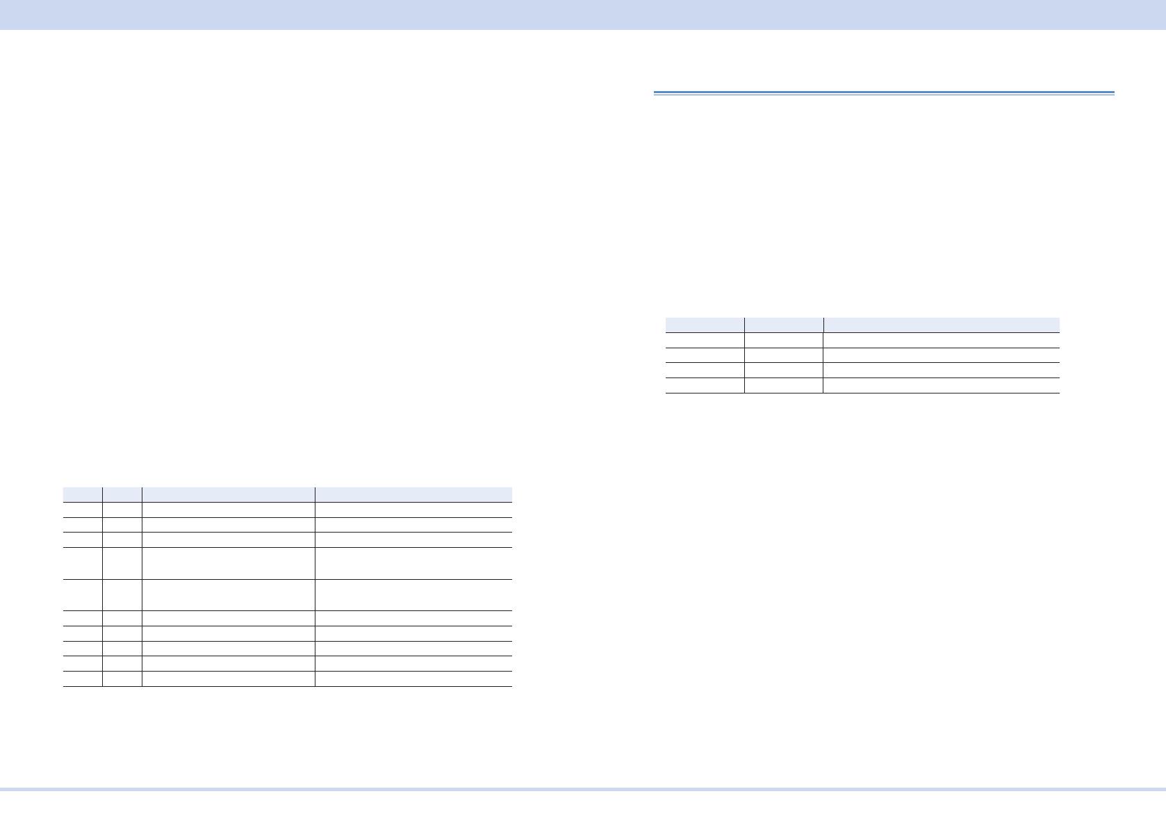
Resetting the LAN interface (LCI/ DEF)
You can use the CONFIG settings to reset the LAN interface (CF60: LCI/ DEF).
When reset, network settings are changed as follows.
The items with an X mark are returned to their default values.
LCI DEF Item Default Value
X X Assignment Method DHCP:ON, Auto-IP:ON, Static:OFF
X DNS Server Assignment 0.0.0.0
X WINS Server Assignment 0.0.0.0
X Desired Hostname <Model name> - <Last 5 digits of serial
number>
X Desired Description KIKUSUI <Model name> Electronic
Load - <Serial number>
X X Enable Dynamic DNS Enable
X X Enable mDNS Enable
X X Enable NetBIOS Over TCP/IP Enable
X X Password Security Not set
X VMCB Setting 0
Accessing and Operating the PWR-01 from a Web Browser (LAN
interface)
You can use the LAN interface to congure detailed settings from a Web browser
on your PC. Use latest version of browser.
The Web site's URL is dened by adding "http://" in front of the PWR-01's IP ad-
dress.
You can enter the URL directly in the address bar of your Web browser by using
the CONFIG settings (CF50 to CF53) to view the IP address.
When you are using a VISA library, a function is available that enables the applica-
tion program (such as National Instruments NI-MAX, Keysight Connection Expert,
and Kikusui KI-VISA Instrument Explorer) to retrieve the VXI-11 measuring instru-
ment. This function is provided by VISA vendors. You can access the PWR-01 by
clicking on the hyperlink that is provided in the retrieval results.
CONFIG Display Description
CF50 0 to 255 Display the 1st number of the IP address
CF51 0 to 255 Display the 2nd number of the IP address
CF52 0 to 255 Display the 3rd number of the IP address
CF53 0 to 255 Display the 4th number of the IP address
(Example) When the IP address is 169.254.7.8
http://169.254.7.8
Interface Setup
KIKUSUI Electronics Corp. PWR-01 Interface Manual
WELCOME page
When you access the PWR-01 from a Web browser, the WELCOME page is dis-
played rst.
The instrument information, network information, and VISA resource (I/O resource)
information appear on the display. Click items in the navigation menu to move to
the other pages.
Turn ON Identify: The LAN LED on the front panel of the connected PWR-01 blinks
so that you can identify it.
Turn OFF Identify: The LAN LED blinking stops.
Remote Control page
You can remotely control the PWR-01 from a browser. The various buttons have
the same functions as those on the front panel of the PWR-01.
WARNING
Should network communication issues occur, the instrument settings
shown in this Browser Web Control page may not represent the actual
state of the instrument. This may result in unexpected hazardous voltag-
es on the output that could result in personal injury, death or damage to
a device under test. Before touching the output or connecting a device
under test always verify the state of the istrument.
Interface Setup
KIKUSUI Electronics Corp. PWR-01 Interface Manual
LAN Cong page
You can display (VIew Mode) and change (Modify Mode) the network settings.
Navigation (View Mode)
Modify Now: Goes to the network setting item editing screen (Modify Mode).
Navigation (Modify Mode)
Undo: Returns the edited contents to the state before editing.
Apply: Applies the edited contents.
Reset: Resets the network settings.
Default: Returns the network settings to the factory default settings.
Back to View Mode: Goes to the network setting item viewing screen (View Mode).
IP Address Assignment
You can set the IP address You can choose between automatic assignment and
assignment of a xed address.
In the case of automatic assignment of IP address, we recommend using the DHCP
server function using a router as far as possible.
If the DHCP server function is not used, it takes about 60 seconds until determi-
nation that address assignment with DHCP has failed. Then, an address between
169.254.0.0 to 169.254.255.255 is assigned by link local address (Auto-IP).
DNS Server Assignment
Sets the address of the DNS server.
WINS Server Assignment
Sets the address of the WINS server.
Hostname & Services
You can set the host name and so on. If you set the host name, you can use it in
place of the IP address to access the LAN interface. Normally, we recommend that
you select “Enable Dynamic DNS”, “Enable mDNS”, and “Enable NetBIOS Over
TCP/IP”.
If you leave the Hostname and Description boxes empty and click “Apply,” the host
name will be created from the model name and serial number.
TCP Ports (View Mode)
The number of the TCP port in use is displayed. You cannot change the port num-
ber.
Interface Setup
KIKUSUI Electronics Corp. PWR-01 Interface Manual
Reset and factory default settings
Clicking Reset and Default changes the network settings change as follows.
The items with an X mark are returned to their default values.
Reset Default Item Default Value
X X Assignment Method DHCP:ON, Auto-IP:ON, Static:OFF
X X DNS Server Assignment 0.0.0.0
X X WINS Server Assignment 0.0.0.0
X Desired Hostname <Model name> - <Last 5 digits of serial
number>
X Desired Description KIKUSUI <Model name> Electronic Load -
<Serial number>
X X Enable Dynamic DNS Enable
X X Enable mDNS Enable
X X Enable NetBIOS Over TCP/IP Enable
Status page
Displays the license information of the open-source software.
Interface Setup
KIKUSUI Electronics Corp. PWR-01 Interface Manual
Security page
You can set and change the password for the Web browser interface here.
When a password has been set, that password is required in order to use the fol-
lowing functions.
Remote control from Remote Control page
Editing of LAN Conguration page
Changing/deleting the password
Set New Password
Enter the password.
You can use alphanumeric characters, hyphens, and underscores for the password.
15 characters maximum. The rst character should be an alphabetical character.
The maximum password length is 15 characters.
Changing/deleting the password
After the password has been set, the screen for changing the password appears
when you enter the password.
To change the password, enter the present password in “Current Password”, enter
the new password in “New Password”and “Conrm Password”, and then click “Ap-
ply”.
To disable password protection, enter the present password in “Current Password”,
leave “New Password”and “Conrm Password” blank, and click “Apply”.
If you forget the password
If you forget the password, reset the LAN interface setting in the CONFIG settings
(CF60: LCI/DEF) or initialize the PWR-01 to its factory default settings.
For datails of CONFIG settings, see the PWR-01 user's manual.
Multichannel Setup
If you use the multichannel (VMCB) function, you can connect one PC to up to 31
PWR-01s to construct a virtual multichannel power supply system. This is useful
when you want to synchronize the operation of multiple PWR-01s or minimize the
number of communication ports that are required.
Multichannel connections
Set one PWR-01 as the master unit (VMCB master unit), and then connect this
PWR-01 to the PC through the LAN, RS232C, or USB interface. The other PWR-
01s are slave units (VMCB slave units). Use a switching hub or broadband router to
connect the slave units to the master unit through the LAN interface. Use standard
LAN cables (category 5).
To a LAN
Port
To a LAN port
Same domain number
VMCB master unit
Channel 0
VMCB slave unit
Channel 1
VMCB slave unit
Channel 30
PC
When the master unit is connected to the PC through the LAN interface
Switching hub or broadband router
Straight
cable
To an RS232C
connector
or a USB port
To a LAN port
VMCB master unit
Channel 0
VMCB slave unit
Channel 1
VMCB slave unit
Channel 30
PC
Switching hub or broadband router
When the master unit is connected to the PC through the RS232C or USB interface
Same domain number
CV
CC
/
W
V
A
ALM RMT LOCK LAN
B CAPRESET
DLY SEQ HBSSVIR
CV
CC
/
W
V
A
ALM RMT LOCK LAN
SC2 SC3 LOCKALM CLR SC1
SHIFT
FINE
FINE
REGULATED DC POWER SUPPLY
OUTPUT
VOLTAGE
CURRENT
CONFIG
PWR DSPMEMORY
LOCALSET OCP OVP
MAX10A
DC OUTPUT
POWER
PWR
CV
CC
/
W
V
A
ALM RMT LOCK LAN
B CAPRESET
DLY SEQ HBSSVIR
CV
CC
/
W
V
A
ALM RMT LOCK LAN
SC2 SC3 LOCKALM CLR SC1
SHIFT
FINE
FINE
REGULATED DC POWER SUPPLY
OUTPUT
VOLTAGE
CURRENT
CONFIG
PWR DSPMEMORY
LOCALSET OCP OVP
MAX10A
DC OUTPUT
POWER
PWR
CV
CC
/
W
V
A
ALM RMT LOCK LAN
B CAPRESET
DLY SEQ HBSSVIR
CV
CC
/
W
V
A
ALM RMT LOCK LAN
SC2 SC3 LOCKALM CLR SC1
SHIFT
FINE
FINE
REGULATED DC POWER SUPPLY
OUTPUT
VOLTAGE
CURRENT
CONFIG
PWR DSPMEMORY
LOCALSET OCP OVP
MAX10A
DC OUTPUT
POWER
PWR
CV
CC
/
W
V
A
ALM RMT LOCK LAN
B CAPRESET
DLY SEQ HBSSVIR
CV
CC
/
W
V
A
ALM RMT LOCK LAN
SC2 SC3 LOCKALM CLR SC1
SHIFT
FINE
FINE
REGULATED DC POWER SUPPLY
OUTPUT
VOLTAGE
CURRENT
CONFIG
PWR DSPMEMORY
LOCALSET OCP OVP
MAX10A
DC OUTPUT
POWER
PWR
CV
CC
/
W
V
A
ALM RMT LOCK LAN
B CAPRESET
DLY SEQ HBSSVIR
CV
CC
/
W
V
A
ALM RMT LOCK LAN
SC2 SC3 LOCKALM CLR SC1
SHIFT
FINE
FINE
REGULATED DC POWER SUPPLY
OUTPUT
VOLTAGE
CURRENT
CONFIG
PWR DSPMEMORY
LOCALSET OCP OVP
MAX10A
DC OUTPUT
POWER
PWR
CV
CC
/
W
V
A
ALM RMT LOCK LAN
B CAPRESET
DLY SEQ HBSSVIR
CV
CC
/
W
V
A
ALM RMT LOCK LAN
SC2 SC3 LOCKALM CLR SC1
SHIFT
FINE
FINE
REGULATED DC POWER SUPPLY
OUTPUT
VOLTAGE
CURRENT
CONFIG
PWR DSPMEMORY
LOCALSET OCP OVP
MAX10A
DC OUTPUT
POWER
PWR
Interface Setup
KIKUSUI Electronics Corp. PWR-01 Interface Manual
Multichannel settings
On the master unit, congure the settings for the connection with the PC, and set
the channel and domain.
On the slave units, congure the LAN settings, and set the channels and domains.
PWR-01s that have the same domain number perform multichannel operations
as a single VMCB network. You can connect up to 31 PWR-01s to a single VMCB
network.
Multichannel uses Multicast DNS (mDNS). Under Hostname / Service on the LAN
CONFIG page accessed through a Web browser, the Enable mDNS check box
must be selected. By default, this check box is selected.
For datails of CONFIG settings, see the PWR-01 user's manual.
- Note -
Within the VMCB network, channel 0 is assigned to the master unit and all other
channel numbers are assigned to slave units. Do not assign the same channel
to two different PWR-01s on the same VMCB network.
Congure all PWR-01s so that they have the same LAN settings (CF61: IP
address assignment method, CF67: VMCB domain number).
Slave unit settings
Normally, you should set DHCP and AUTO IP to ON to set the IP address automat-
ically. For details on the LAN settings, see LAN under Interface Setup.
Congure all PWR-01s on the same VMCB network so that they have the same
CONFIG settings (CF61: IP address assignment method, CF67: VMCB domain
number).
The remote interface setting (CF40) is not valid on slave units.
1
Press CONFIG several times until CF60 is displayed.
2
Turn the VOLTAGE knob until CF61 (IP address assignment method) is
displayed.
3
Use the CURRENT knob to select 110.
DHCP and AUTO IP are set to on, and MANUAL IP is set to off.
If you do not want to use a DHCP server or the AUTO IP function, refer to the us-
er’s manual and set them accordingly.
4
Turn the VOLTAGE knob until CF67 (multichannel (VMCB) domain num-
ber) is displayed.
5
Use the CURRENT knob to set the domain number.
PWR-01s that have the same domain number perform multichannel operations.
Set this value to a number other than 0.
6
Turn the VOLTAGE knob until CF68 (multichannel (VMCB) channel
number) is displayed.
7
Use the CURRENT knob to set the channel number.
Specify a unique channel number on the VMCB network. For a slave unit, set
this value to a number other than 0.
8
Turn the PWR-01 off.
Interface Setup
KIKUSUI Electronics Corp. PWR-01 Interface Manual
Master unit settings
1
Congure the settings for the connection with the PC.
For details on settings for the connection with the PC, see Interface Setup.
2
Press CONFIG several times until CF60 is displayed.
3
Turn the VOLTAGE knob until CF67 (multichannel (VMCB) domain num-
ber) is displayed.
4
Use the CURRENT knob to set the domain number.
PWR-01s that have the same domain number perform multichannel operations.
Set this value to a number other than 0.
5
Turn the VOLTAGE knob until CF68 (multichannel (VMCB) channel
number) is displayed.
6
Use the CURRENT knob to select 0.
Because this is the master unit, set this value to 0.
7
Turn the PWR-01 off.
Caution
The LAN interface can be accessed from any place on the network. If necessary,
congure the security settings. You can apply password protection for security,
and you can restrict the IP addresses to limit the hosts.
Turning power on
First turn the slave units on, and then turn the master unit on. If the PWR-01s are
organized in a rack system, turn all the units on at the same time. If you turn the
master unit on rst, the slave units will not be detected correctly.
When a slave unit turns on, all its LEDs light, and then the following sequence is
displayed: the rated voltage and rated current, the rmware version number, and
then the build number. Each item is displayed for approximately 1 second. Then,
the slave unit displays "I-F SLAV" and enters the wait state. When the PWR-01 is
designated as a slave unit by the master unit, the slave unit enters the operation
wait state.
The slave unit will not stop displaying "I-F SLAV" until it receives the slave designa-
tion from the master unit. Check the CONFIG parameters (CF61, CF67, and CF68)
and the LAN connection. If you change the CONFIG parameters, reboot the PWR-
01.
When the master unit turns on, all its LEDs light, and then the following sequence
is displayed: the rated voltage and rated current, the rmware version number, and
then the build number. Each item is displayed for approximately 1 second. Then,
the master unit displays "FIND CH" and searches for slave units. When the master
unit nishes searching, it enters the operation wait state.
Checking the multichannel conguration
To check the multichannel conguration, send the INSTrument:CATalog? query.
You cannot check the conguration from the panel.
  • Page 1 1
  • Page 2 2
  • Page 3 3
  • Page 4 4
  • Page 5 5
  • Page 6 6
  • Page 7 7
  • Page 8 8
  • Page 9 9
  • Page 10 10
  • Page 11 11
  • Page 12 12
  • Page 13 13
  • Page 14 14
  • Page 15 15
  • Page 16 16
  • Page 17 17
  • Page 18 18
  • Page 19 19
  • Page 20 20
  • Page 21 21
  • Page 22 22
  • Page 23 23
  • Page 24 24
  • Page 25 25
  • Page 26 26
  • Page 27 27
  • Page 28 28
  • Page 29 29
  • Page 30 30
  • Page 31 31
  • Page 32 32
  • Page 33 33
  • Page 34 34
  • Page 35 35
  • Page 36 36
  • Page 37 37
  • Page 38 38
  • Page 39 39
  • Page 40 40
  • Page 41 41
  • Page 42 42
  • Page 43 43
  • Page 44 44
  • Page 45 45
  • Page 46 46
  • Page 47 47
  • Page 48 48
  • Page 49 49
  • Page 50 50
  • Page 51 51
  • Page 52 52
  • Page 53 53
  • Page 54 54
  • Page 55 55
  • Page 56 56
  • Page 57 57
  • Page 58 58
  • Page 59 59
  • Page 60 60
  • Page 61 61
  • Page 62 62
  • Page 63 63
  • Page 64 64
  • Page 65 65
  • Page 66 66
  • Page 67 67
  • Page 68 68
  • Page 69 69
  • Page 70 70
  • Page 71 71
  • Page 72 72
  • Page 73 73
  • Page 74 74
  • Page 75 75
  • Page 76 76
  • Page 77 77
  • Page 78 78
  • Page 79 79
  • Page 80 80
  • Page 81 81
  • Page 82 82
  • Page 83 83
  • Page 84 84
  • Page 85 85
  • Page 86 86
  • Page 87 87
  • Page 88 88
  • Page 89 89
  • Page 90 90
  • Page 91 91
  • Page 92 92
  • Page 93 93
  • Page 94 94
  • Page 95 95
  • Page 96 96
  • Page 97 97
  • Page 98 98
  • Page 99 99
  • Page 100 100
  • Page 101 101
  • Page 102 102
  • Page 103 103
  • Page 104 104
  • Page 105 105
  • Page 106 106
  • Page 107 107
  • Page 108 108
  • Page 109 109
  • Page 110 110
  • Page 111 111
  • Page 112 112
  • Page 113 113
  • Page 114 114
  • Page 115 115
  • Page 116 116
  • Page 117 117
  • Page 118 118
  • Page 119 119

Kikusui PWR801H User manual

Type
User manual

Ask a question and I''ll find the answer in the document

Finding information in a document is now easier with AI