ADLINK Technology CoreModule 730 Reference guide
- Type
- Reference guide

CoreModule
TM
730
(Stackable Single Board Computer)
Reference Manual
P/N 50-1Z019-1000

Notice Page
DISCLAIMER
ADLINK Technology, Incorporated makes no representations or warranties with respect to the contents of
this manual or of the associated ADLINK products, and specifically disclaims any implied warranties of
merchantability or fitness for any particular purpose. ADLINK shall under no circumstances be liable for
incidental or consequential damages or related expenses resulting from the use of this product, even if it has
been notified of the possibility of such damages. ADLINK reserves the right to revise this publication from
time to time without obligation to notify any person of such revisions. If errors are found, please contact
ADLINK at the address shown later in this section.
Audience
This manual provides reference only for computer design engineers, including but not limited to hardware
and software designers and applications engineers. ADLINK Technology, Inc. assumes you are qualified to
design and implement prototype computer equipment.
ii Reference Manual CoreModule 730
TRADEMARKS
CoreModule and the Ampro logo are registered trademarks, and ADLINK, Little Board, LittleBoard,
MightyBoard, MightySystem, MilSystem, MiniModule, ReadyBoard, ReadyBox, ReadyPanel,
ReadySystem, and RuffSystem are trademarks of ADLINK Technology, Inc. All other marks are the
property of their respective companies.
REVISION HISTORY
ADLINK Technology, Incorporated
5215 Hellyer Avenue
San Jose, CA 95138-1007
Tel. 408 360-0200
Fax 408 360-0222
www.adlinktech.com
© Copyright 2009, ADLINK Technology, Incorporated
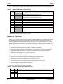
Revision Reason for Change Date
00 Initial Release July/09

CoreModule 730 Reference Manual iii
Contents
Chapter 1 About This Manual ....................................................................................................1
Purpose of this Manual ....................................................................................................................1
References ......................................................................................................................................1
Chapter 2 Product Overview......................................................................................................3
Stackable Architecture ....................................................................................................................3
Product Description..........................................................................................................................4
Module Features ........................................................................................................................4
Block Diagram..................................................................................................................................6
Major Components (ICs)..................................................................................................................7
Header, Connector, and Socket Definitions ....................................................................................9
Jumper Header Definitions ............................................................................................................11
Specifications.................................................................................................................................12
Physical Specifications .............................................................................................................12
Mechanical Specifications ........................................................................................................12
Power Specifications ................................................................................................................13
Environmental Specifications....................................................................................................13
Thermal/Cooling Requirements ................................................................................................13
Chapter 3 Hardware..................................................................................................................15
Overview ........................................................................................................................................15
CPU ..............................................................................................................................................16
Graphics.........................................................................................................................................16
Memory ..........................................................................................................................................16
Interrupt Channel Assignments......................................................................................................16
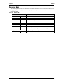
Memory Map ..................................................................................................................................17
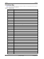
I/O Address Map ............................................................................................................................18
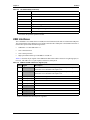
USB Interfaces ..............................................................................................................................19
Ethernet Interface .........................................................................................................................20
Video Interfaces .............................................................................................................................21
VGA Interface ...........................................................................................................................21
LVDS Interface .........................................................................................................................22
Utility Interface ..............................................................................................................................23
Power Button ............................................................................................................................23
Reset Switch.............................................................................................................................23
BIOS Recovery (Using Reset Switch) .................................................................................23
Speaker ....................................................................................................................................23
Miscellaneous ................................................................................................................................23
Battery ......................................................................................................................................23
Real Time Clock (RTC).............................................................................................................23
User GPIO Interface .................................................................................................................24
System Management Bus (SMBus)..........................................................................................24
Ethernet External LED ..............................................................................................................25
Watchdog Timer .......................................................................................................................25
Power Interface..............................................................................................................................25

Contents
iv Reference Manual CoreModule 730
Chapter 4 BIOS Setup .............................................................................................................. 27
Introduction.................................................................................................................................... 27
Entering BIOS Setup (VGA Display) ........................................................................................ 27
OEM Logo Utility (Splash Screen)................................................................................................. 27
Logo Image Requirements....................................................................................................... 27
Appendix A Technical Support .................................................................................................. 29
Index .................................................................................................................................................. 31
List of Figures
Figure 2-1. Stacking Modules with the CoreModule 730 ........................................................... 3
Figure 2-2. Block Diagram ......................................................................................................... 6
Figure 2-3. Component Locations (Front View)......................................................................... 8
Figure 2-4. Component Locations (Back View) ......................................................................... 9
Figure 2-5. Connector Pin Identifications................................................................................. 10
Figure 2-6. Header, Connector, Socket Locations (Front View) .............................................. 11
Figure 2-7. Mechanical Dimensions (Front View).................................................................... 12
List of Tables
Table 2-1. Major Components (ICs) Descriptions and Functions............................................. 7
Table 2-2. Header, Connector, and Socket Descriptions ......................................................... 9
Table 2-3. Jumper Settings .............................................................................................. 11
Table 2-4. Weight and Footprint Dimensions ......................................................................... 12
Table 2-5. Power Supply Requirements ................................................................................. 13
Table 2-6. Environmental Requirements ................................................................................ 13
Table 3-1. Interrupt Channel Assignments ............................................................................. 16
Table 3-2. Memory Map ......................................................................................................... 17
Table 3-3. I/O Address Map ................................................................................................... 18
Table 3-4. USB0 and USB1 Interface Pin Signals (J12) ........................................................ 19
Table 3-5. USB2 and USB3 Interface Pin Signals (J13) ........................................................ 20
Table 3-6. Ethernet Interface Pin/Signal Descriptions (J3)..................................................... 20
Table 3-7. VGA Interface Pin Signals (J7).............................................................................. 21
Table 3-8. LVDS Interface Pin/Signal Descriptions (J8) ......................................................... 22
Table 3-9. Utility Interface Pin Signals (J25) .......................................................................... 23
Table 3-10. User GPIO Interface Pin/Signal Descriptions (J20)............................................... 24
Table 3-11. SMBus Reserved Addresses ................................................................................ 24
Table 3-12. SMBus Pin Signals (J27)....................................................................................... 24
Table 3-13. Ethernet External LED Pin Signals (J26) .............................................................. 25
Table 3-14. Power Interface Pin/Signals (J23) ......................................................................... 25
Table A-1. Technical Support Contact Information ................................................................. 29

CoreModule 730 Reference Manual 1
Chapter 1 About This Manual
Purpose of this Manual
This manual is for designers of systems based on the CoreModule™ 730 stackable single board computer
(SBC) module. This manual contains information that permits designers to create embedded systems based
on specific design requirements.
Information provided in this reference manual includes:
• CoreModule 730 SBC Specifications
• Environmental requirements
• Major chips and features implemented
• CoreModule 730 SBC connector/pin numbers and definitions
• BIOS Setup information
Information not provided in this reference manual includes:
• Detailed chip specifications
• Internal component operation
• Internal registers or signal operations
• Bus or signal timing for industry standard busses and signals
References
The following list of references may be helpful for you to complete your custom design successfully. Some
of these references are also available on the ADLINK’s InfoCenter web page. The InfoCenter was created
for embedded system developers to share ADLINK’s knowledge, insight, and expertise.
Specifications
• SUMIT Specification Revision 1.0, April 4, 2008
Web site: http://www.sff-sig.org/sumit_spec_v10.pdf
• ISM Specification Revision 1.0, June, 2008
Web site: http://www.sff-sig.org/ism_spec_v10.pdf
• PCI 2.2 Specification Revision 2.2, December 18, 1998
Web site: http://www.pcisig.com
Major Integrated Circuit (IC) Specifications
The following chip specifications are used in the CoreModule 730 processor module:
• Intel Corporation and the Atom processor chip
Web site: http://download.intel.com/design/processor/datashts/319535.pdf
• Intel Corporation and the US15W System Controller Hub (SCH)
Web site: http://download.intel.com/design/chipsets/embedded/datashts/319537.pdf
• Analog Devices and the ADM1032ARMZ-1 CPU Temperature Monitor
Web site: http://www.analog.com/static/imported-files/data_sheets/ADM1032.pdf
• Chrontel and the SDVO to RGB Converter
Web site: http://www.chrontel.com/pdf/7317ds.pdf

Chapter 1 About This Manual
2 Reference Manual CoreModule 730
• PLX and the PEX8505 PCIe to PCIe Switch
Web site:
http://www.plxtech.com/pdf/product_briefs/Product_Brief_PEX8505_v1_2_11Apr08.pdf
• Intel Corporation and the 82574IT Gigabit Ethernet controller
Web site: http://download.intel.com/design/network/datashts/82574.pdf
NOTE If you are unable to locate the datasheets using the links provided, search the
internet to find the manufacturer’s web site and locate the documents you need.

CoreModule 730 Reference Manual 3
Chapter 2 Product Overview
This introduction presents general information about the Stackable architecture and the CoreModule 730
single board computer (SBC). After reading this chapter you should understand:
• Stackable architecture
• CoreModule 730 product description
• CoreModule 730 features
• Major components
• Header, Connector, Socket definitions
• Specifications
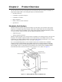
Stackable Architecture
Stackable architecture affords a great deal of flexibility in system design. You can build a simple system
using only a CoreModule single board computer (SBC) and a Compact Flash card in the Compact Flash
socket. To expand a simple CoreModule system, simply add self-stacking ADLINK MiniModule products
or 3rd party stackable expansion boards to provide additional capabilities, such as:
• Additional I/O ports
• Analog or digital I/O interfaces
Stackable expansion modules can be stacked with the CoreModule 730 avoiding the need for card cages and
backplanes. The stackable expansion modules can be mounted directly to the SUMIT connector of the
CoreModule 730. SUMIT-compliant modules can be stacked with an inter-board spacing of ~0.60" (15mm)
so that a 3-module system fits in a 3.6" x 3.8" x 2.4" space. See Figure 2-1.
One or more MiniModule products or other stackable modules can be installed on the CoreModule
expansion connectors. When installed on the SUMIT connectors, the expansion modules fit within the
CoreModule outline dimensions. Most MiniModule products have stack-through connectors compatible
with the SUMIT Version 1.0 specification. Several modules can be stacked on the CoreModule headers.
Each additional module increases the thickness of the package by 0.60" (15mm). See Figure 2-1.
Figure 2-1. Stacking Modules with the CoreModule 730
0.6 inch spacer (8)
4-40 nut (4)
4-40 screw (4)
Stackable Expansion
Modules
Stack-Through
SUMIT Connectors
CoreModule 730

Chapter 2 Product Overview
4 Reference Manual CoreModule 730
Product Description
The CoreModule 730 SBC is an exceptionally high integration, x86-based, PC compatible system in the
ISM (Industry Standard Module) form factor. This rugged and high quality single-board system contains all
the component subsystems of a PC/AT motherboard plus the equivalent of several PC/AT expansion boards.
The CoreModule 730 includes a comprehensive set of system extensions and enhancements that are
specifically designed for embedded systems. These enhancements ensure fail-safe embedded system
operation, such as a watchdog timer and a temperature monitor. This design meets the size, power
consumption, temperature range, quality, and reliability demands of embedded applications and requires
only a single +5V power source.
Embedded and portable applications benefit from the flexibility of the CoreModule 730, making system
design quick and easy. The CoreModule 730 stacks with ADLINK MiniModule products or other SUMIT-
compliant expansion boards or it can serve as the computing engine in a fully customized application.
Module Features
• CPU
♦
Provides x86-based Intel Atom Z530 (1.60GHz) microprocessor
♦
Supports a Front Side Bus (FSB) of 400/533 MHz
♦
Supports IA 32-bit architecture
♦
Provides 32kB Unified Instruction Cache and 24kB Write-Back Data Cache
♦
Provides Low Power and System Management Modes
• SCH (System Controller Hub)
♦
Provides integrated Northbridge and Southbridge
♦
Provides CMOS Front Side Bus signaling
♦
Integrates a DDR2 memory controller with a single 64-bit wide interface
♦
Provides three UHCI USB 1.1 controllers
♦
Provides one EHCI USB 2.0 controllers
• Memory
♦
Provides standard DDR2 SODIMM socket
♦
Supports 533 MHz Clock Speed
♦
Supports non-ECC, unbuffered memory
♦
Supports +2.5V DDR2, 533MHz RAM up to 2GB DDR2 SODIMM
• SUMIT Interface
♦
Provides up to two SUMIT connectors
♦
Supports high-speed serial bus signals
• IDE Interface
♦
Provides one IDE channel
♦
Supports two enhanced IDE devices
♦
Supports Ultra ATA
♦
Supports ATAPI and DVD peripherals
♦
Supports IDE native and ATA compatibility modes

Chapter 2 Product Overview
CoreModule 730 Reference Manual 5
• Compact Flash Socket
♦
Provides Compact Flash socket (Type I or II)
♦
Attached to Primary IDE bus
• Ethernet
♦
Supports IEEE 802.3 10BaseTX/100Base/1000BaseT compatible physical layer
♦
Supports Auto-negotiation for speed, duplex mode, and flow control
♦
Supports full-duplex or half-duplex mode
• Full-duplex mode supports transmit and receive frames simultaneously
• Supports IEEE 802.3x Flow control in full-duplex mode
• Half-duplex mode supports enhanced proprietary collision reduction mode
• Utility Interface
♦
Supports standard external 8Ω “Beep” speaker interface
♦
Supports external Reset switch
♦
Supports external Power button
• USB Ports
♦
Provide three root USB hubs
♦
Provide seven USB ports
♦
Support USB v2.0 EHCI and v1.1 UHCI
• Video (LCD/CRT) Display
♦
Supports full hardware acceleration of H.264 video decode standard
♦
Supports CRT (2048 x 1536) with up to 224MB UMA (Unified Memory Architecture)
♦
Single channel 24-bit LVDS
• Miscellaneous
♦
Provides Real Time Clock and CMOS RAM, with support for battery-free operation
♦
Provides General Purpose I/O (GPIO) interface
♦
Supports customizable Splash Screen
♦
Supports Watchdog Timer (WDT)

Chapter 2 Product Overview
6 Reference Manual CoreModule 730
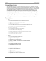
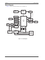
Block Diagram
Figure 2-2 shows the functional components of the CoreModule 730.
Figure 2-2. Block Diagram
LPC
LPC
H8S Controller
(LPC to SPI
Conversion
and Power
Management)
USB0 and USB1
Header
USB2 and USB3
Header
Ethernet
Controller
Ethernet
Magnetics
Gigabit
Ethernet
Header
CK540
Clock
CPU
Temperature
Sensor
SUMIT
Connector - B
SUMIT
Connector - A
DDR2
SODIMM
(up to 2GB)
Intel
US15W
SCH
Intel Atom
Z530
CPU
GPIO
Header
FSB
USB
VGA
Header
LVDS Header
Compact Flash
Socket
IDE
Header
SDVO to RGB
Controller
I2C to SUMIT
SPI to SUMIT
X1 PCIe
X1 PCIe
X1 PCIe
X2 PCIe
X1 PCIe PCIe to PCIe
Switch
SMBus
Header
CM730blkdiag_b

Chapter 2 Product Overview
CoreModule 730 Reference Manual 7
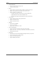
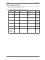
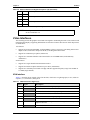
Major Components (ICs)
Table 2-1 lists the major ICs, including a brief description of each, on the CoreModule 730, and Figures 2-3
and 2-4 show the locations of the major ICs on the board.
Table 2-1. Major Components (ICs) Descriptions and Functions
Chip Type Mfg. Model Description Function
CPU (U1) Intel Atom Z530 x86 32-bit processor
offered at 1.6 GHz
Embedded
CPU
Sensor (U2) Analog
Devices
ADM1032ARMZ-1 CPU Temperature
Monitor
Temperature
Monitor and
Alarm
SCH (U3) Intel US15W Graphics, Memory, and
I/O Expansion controller
System
Controller
Hub
Converter (U4) Chrontel CH7317A SDVO to RGB Display
Controller
Digital to
Analog
Conversion
Switch (U10) PLX PEX8505 PCIe to PCIe Switch I/O
Expansion
Interconnect
Controller
(U42)
Intel WG82574IT Ethernet Controller Gigatbit
Ethernet
Transformer
(T1) - on back
of the board;
see Figure 2-4
on page 9
Pulse H5004NL XFMR, 10/100/
1000BaseT
Ethernet
Magnetics

Chapter 2 Product Overview
8 Reference Manual CoreModule 730
Figure 2-3. Component Locations (Front View)
U1
U3
U4
U42
U10
CM730_comp_front_b
U2

Chapter 2 Product Overview
CoreModule 730 Reference Manual 9
Figure 2-4. Component Locations (Back View)
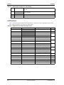
Header, Connector, and Socket Definitions
Table 2-2 describes the headers, connectors, and sockets shown in Figure 2-6. All I/O interfaces use 0.100"
(2.54mm) pitch unless otherwise indicated.
Table 2-2. Header, Connector, and Socket Descriptions
Reference # Access Description
J2 – Memory Front 200-pin, 0.024" (0.60mm) socket for DDR2 SDRAM SODIMM
J3 – Ethernet Front 10-pin, 0.079" (2mm), right-angle header for 10/100/1000BaseT
Gigabit Ethernet port
J5 – SUMIT A Front 52-pin, 0.025" (0.635mm) connector for out-going USB, PCIe,
Power, ACPI, SMBus, I2C, SPI, LPC, Serial, Keyboard, Mouse,
and Clock signals
J6 – SUMIT B Front 52-pin, 0.025" (0.635mm) connector for PCIe and Power
J7 – VGA Front 12-pin, 0.079" (2mm), right-angle, shrouded header for Video
Out
J8 – LVDS Front 20-pin, 0.079" (2mm), right-angle header for Video Out
J9 – IDE Front 44-pin, standard header for primary IDE interface
J10 – Compact Flash
(on back of the board;
see Figure 2-4)
Back 50-pin, 0.050" (1.27mm) socket for Type I or II Compact Flash
cards
J10
T1
CM730_comp_back_b

Chapter 2 Product Overview
10 Reference Manual CoreModule 730
Figure 2-5. Connector Pin Identifications
J12 – USB0 & USB1 Front 10-pin, 0.079" (2mm), right-angle header for USB0 and USB1
ports
J13 – USB2 & USB3 Front 10-pin, 0.079" (2mm), right-angle header for USB2 and USB3
ports
J17 – BATT Front 2-pin, 0.049" (1.24mm), shrouded header for power from
external battery
J20 – GPIO Front 10-pin, 0.079" (2mm) header for General Purpose I/O
J23 – Power In Front 10-pin, right-angle header for receiving external power
J25 – Utility Front 5-pin header for Power Button, Reset, and Speaker
J26 – Ethernet LED Front 4-pin, 0.049" (1.25mm) header for external Gigabit Ethernet
LED
J27 – SMBus Front 5-pin, 0.049" (1.25mm) header for Clock, Data, and Power I/O
NOTE The pinout tables in Chapter 3 of this manual identify pin sequence using the
following methods: A 20-pin header with two rows of pins, using odd/even
numbering, where pin 2 is directly across from pin 1, is noted as 20-pin, 2 rows, odd/
even (1, 2). Alternately, a 20-pin connector using consecutive numbering, where pin
11 is directly across from pin 1, is noted in this way: 20-pin, 2 rows, consecutive (1,
11). The second number in the parenthesis is always directly across from pin 1. See
Figure 2-5.
Table 2-2. Header, Connector, and Socket Descriptions (Continued)
20-pin, two rows,
Consecutive, (1, 11)
Or
1
2
3
4
5
6
7
8
9
10
20
19
124
15 1120
10
53
20-pin, two rows,
Odd/Even, (1, 2)
CM730_ConNum_a

Chapter 2 Product Overview
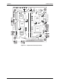
CoreModule 730 Reference Manual 11
Figure 2-6. Header, Connector, Socket Locations (Front View)
Jumper Header Definitions
Table 2-3 describes the jumper headers shown in Figure 2-6.
Note: All jumper headers use 0.079" (2mm) pin spacing.
NOTE Pin 1 is shown as a black pin (square or round) on vertical headers in all
illustrations. Black dots on right-angle headers indicate pin 2.
Table 2-3. Jumper Settings
Jumper # Installed Removed/Installed
JP2 – LVDS Voltage
Select
+3.3 Volts (Pins 1-2) Default +5 Volts (Pins 2-3)
JP3 – IDE Select Enable HDD master, CF slave (Pins 1-2)
Default
Enable HDD slave, CF master
(Pins 2-3)
JP4 – Compact Flash
Voltage Select
+5 Volts (Pins 1-2) +3.3 Volts (Pins 2-3) Default
JP8 – N/A For manufacturing only For manufacturing only
JP9 – Clear CMOS Normal (pins 1-2) Default Clear CMOS Setup (pins 2-3)
J25 J27
J26
JP8
JP3
JP4
JP9
J20
J17
J9
J3
J12
J13
J6
J5
J23
J8
J2
CM730_conn_front_b

Chapter 2 Product Overview
12 Reference Manual CoreModule 730
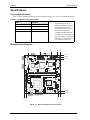
Specifications
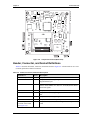
Physical Specifications
Table 2-4 shows the physical dimensions of the module, and Figure 2-7 shows the mounting dimensions.
Mechanical Specifications
Figure 2-7. Mechanical Dimensions (Front View)
Table 2-4. Weight and Footprint Dimensions
Item Dimension
NOTE Height is measured from the
upper board surface to the
highest permanent component
(J25 Utility header) on the
upper board surface. This does
not include the heatsink.
Component height should not
exceed 0.435" (11.05mm) from
the upper surface of the board
and 0.100" (2.54mm) from the
lower surface of the board.
Weight 0.105 kg. (0.232 lbs.)
Height (upper surface) 10.16mm (0.40")
Width 90.170mm (3.550")
Length 95.885mm (3.775")
CM730_mech_dwg_top_b
0.000
3.150
3.350
0.200
0.200
0.650
0.000
0.300
1.693
2.900
0.000
0.185
3.575
3.375

Chapter 2 Product Overview
CoreModule 730 Reference Manual 13
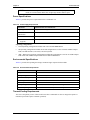
Power Specifications
Table 2-5 provides the power requirements for the CoreModule 730.
Operating configurations:
• In-rush operating configuration includes CRT video and 2GB DDR2 RAM.
• Idle operating configuration includes the In-rush configuration as well as on-board 128MB Compact
Flash, one IDE hard drive, one mouse, and one keyboard.
• *BIT = Burn-In-Test operating configuration includes Idle configuration as well as one USB Compact
Flash reader with 64MB Compact Flash and one USB CD-ROM drive.
Environmental Specifications
Table 2-6 provides the operating and storage condition ranges required for this module.
Thermal/Cooling Requirements
The CPU is the primary source of heat on the board. The CoreModule 730 CPU is designed to operate at
maximum speed and requires a heatsink (provided).
NOTE All dimensions are given in inches. Pin 1 is shown as a black pin (square or
round) on vertical headers. Black dots on right-angle headers indicate pin 2.
Table 2-5. Power Supply Requirements
Parameter Characteristics for 1.6GHz CPU
Input Type Regulated DC voltages
In-rush Current
(Maximum)
6.69A (33.45W)
Idle Power 0.17A (0.85W)
BIT* Current
(Typical)
0.60A (3.00W)
Table 2-6. Environmental Requirements
Parameter Conditions
Temperature
Operating –20° to +70° C (–4° to +158° F)
Extended (Optional) –40° to +85° C (–40° to +185° F)
Storage –55° to +85° C (–67° to +185° F)
Humidity
Operating 5% to 90% relative humidity, non-condensing
Non-operating 5% to 95% relative humidity, non-condensing

Chapter 2 Product Overview
14 Reference Manual CoreModule 730

CoreModule 730 Reference Manual 15
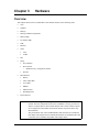
Chapter 3 Hardware
Overview
This chapter discusses the ICs and headers of the module features in the following order:
• CPU
• Graphics
• Memory
• Interrupt Channel Assignments
• Memory Map
• I/O Address Map
• USB
• Ethernet
• Video
♦
VGA
♦
LVDS
• LPC
• Utility
♦
Power Button
♦
Reset Switch
• BIOS Recovery (Using Reset Switch)
♦
Speaker
• Miscellaneous
♦
Battery
♦
Time of Day/RTC
♦
User GPIO
♦
SMBus
♦
Ethernet LED
♦
Watchdog Timer
• Power Interface
NOTE ADLINK Technology, Inc. only supports the features and options listed in this
manual. The main components used on the CoreModule 730 may provide more
features or options than are listed in this manual. Some of these features/options
are not supported on the module and will not function as specified in the chip
documentation.
The pinout tables only of non-standard headers and connectors are included in
this chapter. This chapter does not include pinout tables for standard headers and
connectors such as SUMIT, 44-pin IDE, and Compact Flash.

Chapter 3 Hardware
16 Reference Manual CoreModule 730
CPU
The CoreModule 730 offers an embedded microprocessor—the Intel Atom Z530—operating at 1.6 GHz.
This CPU provides a powerful x86 core and support for the SCH (System Controller Hub) US15W which
integrates Northbridge and Southbridge functions.
Graphics
The US15W SCH integrates a graphics controller which provides LVDS and SDVO ports that terminate to
LVDS and VGA headers, respectively. The graphics controller achieves high 2D and 3D performance with a
DDR2 memory interface (shared with the system controller) supporting a bandwith of up to 2 GB (DDR2 @
up to 533 MHz.)
Memory
The CoreModule 730 provides one 200-pin DDR2 SODIMM of up to 2GB of SDRAM memory, which is
shared between the system memory controller and the graphics memory controller in the SCH.
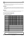
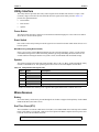
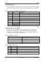
Interrupt Channel Assignments
The interrupt channel assignments are shown in Table 3-1.
Legend: D = Default, O = Optional, X = Fixed, * = Located on the optional expansion module.
Table 3-1. Interrupt Channel Assignments
Device vs IRQ No. 0 1 2 3 4 5 6 7 8 9 10 11 12 13 14 15
Timer X
Keyboard* X
Secondary Cascade X
COM1* O D O O
COM2* D O O O
COM3* O O O D
COM4* O O D O
Parallel* O D O O
RTC X
IDE D
Math Coprocessor X
PS/2 Mouse* X
PCI INTA* Automatically Assigned
PCI INTB* Automatically Assigned
PCI INTC* Automatically Assigned
PCI INTD* Automatically Assigned
PCI INTE Automatically Assigned
PCI INTF Automatically Assigned
PCI INTG Automatically Assigned
PCI INTH Automatically Assigned
NOTE The PCI IRQs for the Ethernet, Video, and Internal Local Bus are automatically
assigned by the BIOS Plug and Play logic. Local ISA IRQs assigned during
initialization can not be used by external devices.
Page is loading ...
Page is loading ...
Page is loading ...
Page is loading ...
Page is loading ...
Page is loading ...
Page is loading ...
Page is loading ...
Page is loading ...
Page is loading ...
Page is loading ...
Page is loading ...
Page is loading ...
Page is loading ...
Page is loading ...
Page is loading ...
-
 1
1
-
 2
2
-
 3
3
-
 4
4
-
 5
5
-
 6
6
-
 7
7
-
 8
8
-
 9
9
-
 10
10
-
 11
11
-
 12
12
-
 13
13
-
 14
14
-
 15
15
-
 16
16
-
 17
17
-
 18
18
-
 19
19
-
 20
20
-
 21
21
-
 22
22
-
 23
23
-
 24
24
-
 25
25
-
 26
26
-
 27
27
-
 28
28
-
 29
29
-
 30
30
-
 31
31
-
 32
32
-
 33
33
-
 34
34
-
 35
35
-
 36
36


ADLINK Technology CoreModule 730 Reference guide
- Type
- Reference guide
Ask a question and I''ll find the answer in the document
Finding information in a document is now easier with AI
Related papers
-
ADLINK Technology CoreModule 430 Owner's manual
-
-
-
-
-
-
-
-
-
Other documents
-
Ampro ReadyBoar 800 Reference guide
-
-
-
 RED ATOM 12 Burial Landscape Subwoofer Owner's manual
-
-
Ampro Corporation COREMODULE PCI-104 User manual
-
-
-
-
