STEINEL RS 10 L Owner's manual

Category
Ceiling lighting
Type
Owner's manual

This manual is also suitable for

Installation
Important: Make sure the installation site is
not sub-
ject to
vibration.
Connecting a dimmer will result in damage to the
SensorLight.
Please note that the light must be protected by a 10 A
circuit breaker.
Installation procedure:
Before mounting the RS 21 L on the wall or ceiling,
first fit the glass shade clips and adjust the glass
shade (refer to drawing on page 3).
1. Hold enclosure against the wall/ceiling and
mark drill holes, paying attention to any existing
wiring in the wall/ceiling.
2. Drill the holes, insert wall plugs (6 mm dia.).
3. Fit and pierce sealing plug for mains supply lead.
4. Pass mains power supply lead though and fit the
heat-resistant wire insulator provided.
5. Screw enclosure into place.
6. Connecting the mains power supply lead (see fig.).
The mains power supply lead is a 3-core
cable:
L = phase conductor (usually black or brown)
N = neutral conductor (usually blue)
PE = protective earth conductor (green/yellow)
If you are in any doubt, identify the conductors using
a voltage tester; switch off the current again. Connect
the phase conductor (L) and neutral conductor (N) to
the terminal block. Insulate any PE protective earth
conductor with adhesive tape.
Technical specifications
Wattage: RS 14/15/16/16-x L: 60 W/E 27 max.
plus 100 VA max. (e.g. bathroom/WC fan extractor)
RS 10/10-x/13/21 L: 75 W/E 27 max.
RS 100/103 L: 100 W/E 27 max.
RS 104 - 110 L: 2 x 40 W/G 9 max.
plus 800 VA max. (e.g. bathroom/WC fan extractor)
Connection: 230 – 240 V, 50 Hz
Installation site: indoors, wall/ceiling mounting
HF system: 5.8 GHz CW radar, ISM band
Transmission power: approx. 1 mW
Detection: 360°, 160° opening angle, if necessary through glass, wood and stud walls
Reach: 1 – 8 m dia., infinitely variable
3 – 8 m dia. (RS 15 L, RS 16/16-2/16-3 L)
Time setting: 5 sec. to 15 min.
Twilight setting: 2 – 2000 lux
Enclosure: IP 44 (IP 20 RS 21 L)
Protection class: II
Power consumption: approx. 0.9 W
Temperature ranging from: - 10° C to + 50° C
- 13 -
Important: Reversing the connections will result in a
short-circuit in the light unit or in your fuse box later
on. In this case, you must identify the individual con-
ductors once again and re-connect them. A mains
switch for switching the unit ON and OFF may of
course be installed in the mains power supply lead.
7. Set functions , , .
8. Fit glass shade and secure in place either by turn-
ing or by means of the spring clips (RS 21 L).
Surface wiring:
Surface wiring may be carried out as illustrated in the
diagrams, no. 9 respectively, on pages 2 to 3.
Connection of an additional load
An additional load (100 VA maximum, e.g. bath-
room/WC fan extractor) may be connected to the
SensorLight and will then be switched on and off by
the sensor light's electronics. Screw the load's live
conductor to the terminal marked L’. First remove the
protective cap with a pair of pliers. The cables must
also be fitted with the heat-resistant wire insulator.
Loop neutral conductor (N) as well as any protective
earth conductor (PE) through from the distribution
box. ( see wiring diagram on page 4 )
Installation instructions
Dear Customer,
Congratulations on purchasing your new STEINEL
SensorLight and thank you for the confidence you
have shown in us. You have chosen a high-quality
product that has been manufactured, tested and
packed with the greatest care.
Please familiarise yourself with these instructions
before attempting to install the SensorLight because
prolonged reliable and trouble-free operation will only
be ensured if it is fitted properly.
We hope your new STEINEL SensorLight will bring
you lasting pleasure.
GB
System components
Enclosure
Reach setting
(1 – 8 m dia.)*
Time setting
(5 sec. – 15 min.)
Twilight setting
(2 – 2000 lux)
HF sensor
Glass shade
Glass shade clips
(screw-fastenable)
Spring clip
Spacers for surface wiring
Metal shrouds (not for RS 16, RS 16-2,
RS 16-3, RS 15 L)
Snap ring for adjusting square glass shades
Principle
The SensorLight is an active motion detector. The
integrated HF sensor emits high-frequency electro-
magnetic waves (5.8 GHz) and receives their echo.
The sensor detects the change in echo from even
the slightest movement in the light's detection zone.
A microprocessor then triggers the "switch light ON"
command. Detection is possible through doors,
panes of glass or thin walls.
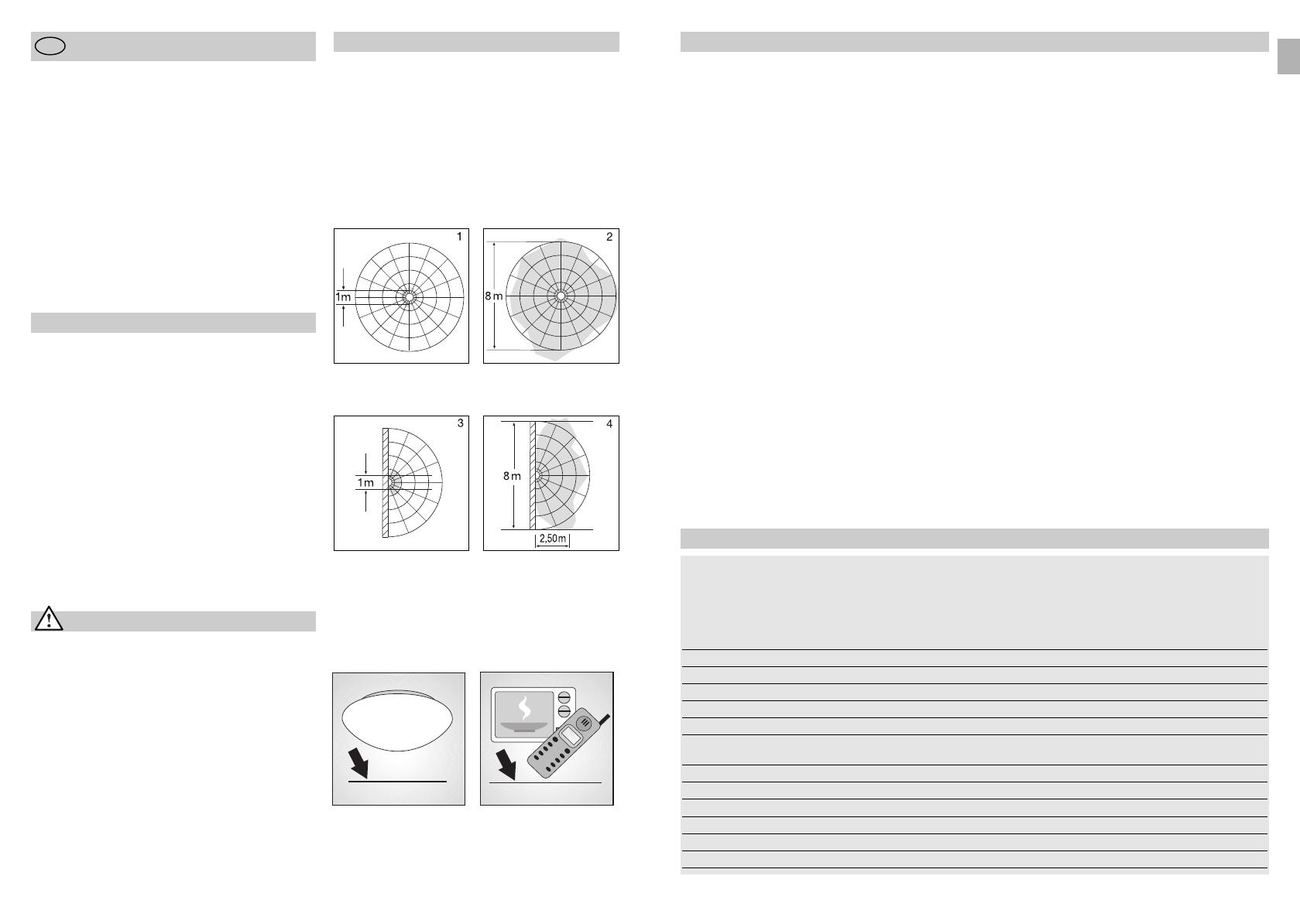
Detection zones for ceiling mounting:
1) Minimum reach (1 m dia.)*
2) Maximum reach (8 m dia.)*
Important: Persons or objects moving towards the
light are detected best.
Detection zones for wall mounting:
3) Minimum reach (1 m dia.)*
4) Maximum reach (8 m dia.)*
Safety warnings
Disconnect the power supply before attempting any
work on the unit.
The electrical connection lead must be dead during
installation. Therefore, switch off the power first and
check that the circuit is dead using a voltage tester.
Installing the sensor light involves work on the
mains voltage supply. This work must therefore
be carried out professionally in accordance with
applicable national wiring regulations and electrical
operating conditions.
(
D
-VDE 0100,
A
-ÖVE /
ÖNORM E8001-1,
-SEV 1000)
Note:
The high-frequency output of the HF sensor is approx.
1 mW – that's just 1,000th of the transmission power
of a mobile phone or microwave oven.
approx. 1 mW
approx. 1000 mW
- 12 -
GB
* 3 – 8 m dia. (RS 15 L, RS 16/16-2/16-3 L)
BDAL Serie RS_24spr_neu 27.07.2011 11:06 Uhr Seite 13
- 15 -
Troubleshooting
SensorLight without power
SensorLight will not switch ON
SensorLight will not switch OFF
SensorLight switches on without
any identifiable movement
SensorLight does not switch ON
despite movement
Malfunction
House fuse faulty, not switched ON,
break in wiring
Short circuit in mains power supply
lead
Any mains switch OFF
Renew house fuse, switch ON
mains power switch, check wiring
with voltage tester
Connect connections
Switch on mains power switch
Wrong twilight setting selected
Bulb faulty
Mains switch OFF
House fuse faulty
Adjust setting
Change bulb
Switch ON
Renew house fuse,
check connection if necessary
Continuous movement
in the detection zone
Check zone setting
Light mounting surface is subject to
vibration
Movement occurred, but not identi-
fied by the sensor (movement behind
wall, movement of a small object in
immediate lamp vicinity etc.)
Securely mount enclosure
Check zone setting
Rapid movements are being sup-
pressed to minimise malfunctioning
or the detection zone you have set
is too small
Check zone setting
Cause Remedy
The SensorLight can be put into operation as soon as
the enclosure has been fitted and the SensorLight
has been connected to the mains power supply.
Putting the light into operation manually at the light
switch turns it off after 10 secs. for the calibration
phase. Once calibrated, it is activated for the sensor
mode. It is not necessary to operate the light switch a
second time.
Reach setting (sensitivity)
Reach is the term used to describe the
diameter of the more or less circular
detection zone produced on the
ground after mounting the sensor
light at a height of 2.5 m. Turn the
reach control fully anticlockwise to
select minimum reach (approx. 1 m
dia.)*, and fully clockwise to select maximum reach
(approx. 8 m dia.)*. (The light leaves the factory set to
maximum reach.)
Time setting (switch-off delay)
The light can be set to stay ON for
any period of time between approx.
5 sec. (control turned fully anti-
clockwise) and a maximum of 15 min.
(control turned fully clockwise).
(The light leaves the factory set to the
shortest time.) Any movement detect-
ed before this time elapses will re-start the timer. It is
recommended to select the shortest time for adjusting
the detection zone and for performing the walk test.
Note: After the light switches OFF, it takes approx.
1 sec. before it is able to start detecting movement
again. The light will only switch on in response to
movement once this period has elapsed.
Twilight setting (response threshold)
The chosen light response threshold
can be infinitely varied from approx.
2–2000 lux. Turn control fully anti-
clockwise to select dusk-to-dawn
operation at about 2 lux. Turn control
fully clockwise to select daylight
operation at about 2000 lux. (The
light leaves the factory set to daylight operation.) The
control must be turned fully clockwise when adjusting
the detection zone and performing the walk test in
daylight.
Functions
- 14 -
1 m – 8 m dia.*
Functional Warranty
This STEINEL product has been manufactured with
great care, tested for proper operation and safety in
accordance with applicable regulations and then sub-
jected to random sample inspection. STEINEL guar-
antees that it is perfect condition and proper working
order. The warranty period is 36 months, starting on
the date of sale to the consumer. We will remedy
defects caused by material flaws or manufacturing
faults. The warranty will be met by repair or replace-
ment at our own discretion. The warranty shall not
cover damage to wear parts, damage or defects
caused by improper treatment or maintenance.
Further consequential damage to other objects is
excluded.
Claims under the warranty will only be accepted if the
unit is sent fully assembled and well packed complete
with a brief description of the fault, a receipt or
invoice (date of purchase and dealer's stamp) to the
appropriate Service Centre.
Repair Service:
Our Customer Service Department
will repair faults not covered by
warranty or after the warranty period.
Please send the product well
packed to your nearest Service
Centre.
36
Declaration of conformity
This product complies with
- Low Voltage Directive 2006/95/EC
- EMC Directive 2004/108/EC
- RoHS Directive 2002/95/EC
- RTTE Directive 1999/05/EC
5 sec. – 15 min.
2 – 2000 lux
GB
* 3 – 8 m dia. (RS 15 L, RS 16/16-2/16-3 L)
BDAL Serie RS_24spr_neu 27.07.2011 11:06 Uhr Seite 15
  • Page 1 1
  • Page 2 2
  • Page 3 3
  • Page 4 4
  • Page 5 5
  • Page 6 6
  • Page 7 7
  • Page 8 8
  • Page 9 9
  • Page 10 10
  • Page 11 11
  • Page 12 12
  • Page 13 13
  • Page 14 14
  • Page 15 15
  • Page 16 16
  • Page 17 17
  • Page 18 18
  • Page 19 19
  • Page 20 20
  • Page 21 21
  • Page 22 22
  • Page 23 23
  • Page 24 24
  • Page 25 25
  • Page 26 26
  • Page 27 27
  • Page 28 28
  • Page 29 29
  • Page 30 30
  • Page 31 31
  • Page 32 32
  • Page 33 33
  • Page 34 34
  • Page 35 35
  • Page 36 36
  • Page 37 37
  • Page 38 38
  • Page 39 39
  • Page 40 40
  • Page 41 41
  • Page 42 42
  • Page 43 43
  • Page 44 44
  • Page 45 45
  • Page 46 46
  • Page 47 47
  • Page 48 48
  • Page 49 49
  • Page 50 50
  • Page 51 51
  • Page 52 52

STEINEL RS 10 L Owner's manual

Category
Ceiling lighting
Type
Owner's manual
This manual is also suitable for

Ask a question and I''ll find the answer in the document

Finding information in a document is now easier with AI