Craftsman 921.1531 User manual

Category
Air compressors
Type
User manual

This manual is also suitable for

Owner's Manual
AIR COMPRESSOR
3-gallon
1.5 HP (max developed)
1 HP Running
Oil Lubricated
Model No. 921.153100
CAUTION:
Before using this product,
read this manual and follow
all its Safety Rules and
Operating Instructions.
Safety instructions
Installation & Operation
Maintenance & Storage
Troubleshooting Guide
Parts List
Espa_ol, p. 10
Sears, Roebuck and Co., Hoffman Estates, IL 60179 U.S.A.
www.sears.com/craftsman
06/17#2004
Part NO. E100731
TABLE OF CONTENTS
Page
Warranty ...................... ,................................................................................ see below
Safety Instructions ................................................................................................. 1
Important Safety Instructions & Guidelines ........................................................... 1
Specifications ......................................................................................................... 2
Glossary ................................................................................................................ 2
Duty Cycle ............................................................................................................. 2
Parts & Features ................................................................................................... 3
installation & Assembly ......................................................................................... 4
Operating Procedures ........................................................................................... 5
Maintenance .......................................................................................................... 6
Storage .................................................................................................................. 6
Troubleshooting Guide .......................................................................................... 7
Parts List................................................................................................................. 8
EspaSol.................................................................................................................... 10
Service Number.......................................................................................... back cover
ONE YEAR FULL WARRANTY ON CRAFTSMAN AIR COMPRESSOR
If this Craftsman Air Compressor fails due to manufacturer's defects in material or workmanship
within one year of the date of purchase, RETURN IT TO THE NEAREST SEARS STORE OR
SERVICE CENTER IN THE UNITED STATES and it will be replaced or repaired (at our option),
free of charge.
If this Air Compressor is used for commercia?or rental purposes, this warrantyapplies for only 90
days from the date of purchase. This warranty gives you specific legal rights and you may also
have other rights which vary from state to state.
Sears, Roebuck and Co., Dept. 817WA,
Hoffman Estates, IL 60179
Safety Instructions
The information listed below should be read and
understood by the operator. This information is given to
_rotect the user while operating and storingthe air
compressor. We utnize the symbols below to allow the
reader to recognize important information about their
safety.
Indicates an imminently hazardous situation which, if not
avoided, will result in death or serious injury.
Indicates a potentially hazardous situation which, if not
avoided, could result in death or serious injury
Indicates a potentially hazardous situation which, if not
avoided, may result in minor or moderate injury.
When used without the safety alert symbol indicates a
potentially hazardous situation which, if not avoided, may
result in property damage.
Important Safety Instructions and Guidelines
Save all instructions
Improper operation or maintenance of this product could result in serious injury and/or property damage. Read and
understand all of the warnings and safety instructions provided before using this equipment.
Risk of Moving Parts
Risk of Burns
N
Risk of Falling
Risk from
Flying Objects
The air compressor should be operated on a dedicated 15 amp circuit. If the circuit does
not have 15 free amps available, a larger circuit must be used. Always use more air
hose before utilizing extension cords. All extension cords used must be 12 gauge with
a maximum length of 25 ft. The circuit fuse type must be a time delay. Low voltage could
cause damage to the motor.
If the air compressor is in operation, all guards and covers should be attached or
installed correctly. If any guard or cover has been damaged, do not operate the
equipment until the proper personnel has correctly repaired the equipment. The power
cord should be free of any moving parts, twisting and/or crimping while in use and while
in storage.
There are surfaces on your air compressor that while in operation and thereafter can
cause serious burns if touched. The equipment should be allowed time to cool before
any maintenance is attempted. Items such as the compressor pump and the outlet tube
are normally hot during and after operation.
Operation of the air compressor should always be in a position that is stable. Never use
the air compressor on a rooftop or elevated positionthat could allow the unit to fall or
be tipped over. Use additional air hose for elevated jobs.
Always wear ANSI Z87.1 approved safety glasses with side shields when the air
compressor is in use. Turn off the air compressor and drain the air tank before
performing any type of maintenance or disassembly of the hoses or fittings. Never point
any nozzle or sprayer toward any part of the body or at other people or animals.
Important Safety Instructions & Guidelines
Risk to Breathing
Risk of
Electrical Shock
Risk of
Explosion or Fire
Risk of Bursting
Specifications
Avoid using the air compressor in confined areas. Always have adequate space
(12 inches) on all sides of the air compressor. Also keep children, pets, and others out
of the area of operation. This air compressor does not provide breathable air for anyone
or any auxiliary breathing device. Spraying material will always need to be in another
area away from the air compressor to not allow intakeair to damage the air compressor
filter.
Never utilize the air compressor in the rain or wet conditions. Any electrical issues or
repairs should be performed by authorized personnel such as an electrician and should
comply with all national and local electrical codes. The air compressor should also have
the proper three prong grounding plug, correct voltage, and adequate fuse protection.
Never operate the compressor near combustible materials, gasoline or solvent vapors.
If spraying flammable materials, locate the air compressor at least 20 feet away from
the spray area. Never operate the air compressor indoors or in a confined area.
Always drain the air compressor tank daily or after each use. if the tank develops a leak,
then replace the air compressor. Never use the air compressor after a leak has been
found or try to make any modifications to the tank. Never modify the air compressor's
factory settings which control the tank pressureor any other function.
Pump ...................... Oil-lube direct drive
Motor Induction ............... 1.5 HP max developed,
1HP running
Bore ....................... 1.65"
Stroke ...................... 1.26"
Voltage Single Phase ........... 120 VAC
Minimum Circuit Requirement .... 15 Amps
Air Tank Capacity ............. 3 Gallons
Cut-in Pressure ............... 95 PSI
Cut-out Pressure .............. 125 PSI
SCFM @ 90 PSI .............. 2.4
Glossary
CFM: Cubic feet per minute.
SCFM: Standard cubic feet per minute; a unit of measure
for air delivery.
PSIG: Pounds per square inchgauge; a unitof measure
for pressure.
ASME: American Society of MechanicalEngineers.
California Code: Unit may complywith California Code
462 (I) (2)/(M) (2).
Cut-In Pressure: The air compressorwillautomatically
startto refillthe tank when the pressure drops
below the prescribed minimum.
Duty Cycle
Cut-Out Pressure: The point at which the motor stops
when the tank has reached maximum air
pressure.
Code Certification: Products that bear one or more of
the following marks: UL, CUL, ETL, CSA, have
been evaluated by OSHA-certified independent
safety laboratories and meet the applicable
Underwriters Laboratories Standards for Safety.
This is a 50% duty cycle air compressor. Do not run the air compressor more than 30 minutes of one hour. Doing so
could damage the air compressor.
2
Parts & Features
See figures below for reference.
Air Intake Filter
Provides clean air to the pump and must always be kept free of debris. Check on a daily basis or before each use.
I Regulator Gauge
Indicates the outgoing air pressure to the tool and iscontrolled
by the regulator.
Outlet Tube
Oil Fill Cap
J
Tank Pressure Gauge
Indicates the reserve air pressure inthe tank.
Pressure Switch
Thiscontrolsthe powerto the motorand also the
cut-in/cut-outpressuresettings. This switchserves
as theAuto-On/Off positionsfor the unit,
Pressure Relief Valve
The pressure relief valve located on the
side of the pressure switch, isdesigned to
automaticallyrelease compressedair when
the air compressorreachescut-outpressure.
The released air should onlyescape
momentarilyand the valve shouldthen close.
Oil Sight Gauge
Pressure
Relief Tube
Safety Valve 1
Used to allow excess tank pressure to
escape intothe atmosphere.This valve
should only open when the tank pressure
isabove the maximum rated pressure.
Re_,.gulator
Ine air pressure coming from the air tank is
controlled by the regulator. To increase the
pressure turn the knob clockwise and to
decrease the pressure turn the knob
counterclockwise.
Quick Connect 1Offers a quick release feature for attaching and removing the air hose.
Tank Drain Valve /
Used to drain condensation from the air tank, Locatedat bottom of tank.
I Check Valve 1When the pump is not in operation the valve closes to retain air pressure inside the tank. An internal component.
Installation & Assembly
The air compressor should be turned off and unplugged from
the power source before any maintenance is performed as
well as the air bled from the tank and the unit allowed time
to cool. Personal injuries could occur from moving parts,
electrical sources, compressed air or hot surfaces. The
regulator assembly must be attached before use. Failure to
assemble correctly could result in leaks and possible injury.
If unsure of assembly instructions or you experience difficulty
in the assembly please call your local service department for
further instruction.
Quick Connect Assembly
1. Before assembly be sure that the
Quick Connect (Q.C.) threads have a
sealant applied from the factory to prevent
leaks around the threads. If no sealant is
present, wrap the threaded portion with
Teflon tape.
2. Attach the Q.C. assembly to the air compressor by
aligning the Q.C. threads to the regulator on the manifold.
Be certain to align the threads before tightening to prevent
thread damage.
3. The assembly should turn clockwise 1 to 1.5 revolutions
after hand-tightening with a 13/16ths size wrench. To prevent
damage and leaks, do not
over-tighten.
To Install the Air Intake Filter
Remove the air intake filter from the
poly bag and thread it onto the head
of the compressor as shown.
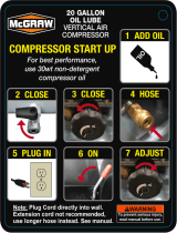
Do not attempt to start the air compressor without first adding
oil to the crankcase. Serious damage can result unless filled
with oil. The pump is shipped without oil from the factory.
Only use non-detergent oils since multi-viscosity motor oils
leave carbon deposits on pump components, thus reducing
performance and compressor life.
Drain the tank to release all tank air _ _.=t_{ '_L
pressure before removing the oil fill cap.
Be sure the air vent in the oil fill cap (see
figure to the right) is free from debris.
If air vent is blocked, pressure can build
in crankcase causing damage to the
compressor and possible personal injury.
Lubrication and Oil
Remove the oil fill cap by turning it _ /_-,,,
counter-clockwise by hand. Fillthe
compressor pump with an air compressor
oil such as SAE-30 non-detergent (API
CG/CD Heavy Duty) oil at slow intervals
until the oil reaches the center of the red
circle in the sight glass ( see figure above).
Use SAE-10 during extreme winter conditions.
Location of the Air Compressor
The air compressor should always be located in a clean,
dry, and well ventilated environment. The unit should have
at minimum, 12 inches of space on each side. The air filter
intake should be free of any debris or obstructions. Check
the air filter on a daily basis to be sure it is clean and in
working order.
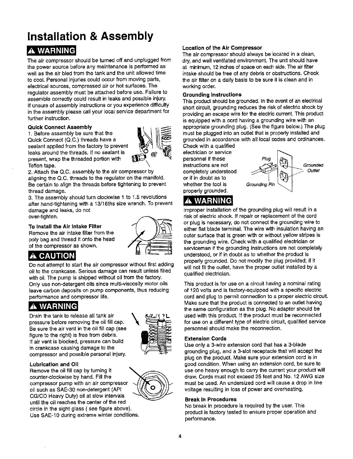
Grounding instructions
This product should be grounded. In the event of an electrical
short circuit, grounding reduces the risk of electric shock by
providingan escape wire for the electric current. This product
is equipped with a cord having a grounding wire with an
appropriate grounding plug. (See the figure below.) The plug
must be plugged intoan outlet that isproperly installed and
grounded in accordance with all local codes and ordinances.
Check with a qualified
electrician or service
personnel if these
instructions are not
completely understood
or if in doubt as to
whether the tool is
properly grounded.
Grounded
Outlet
Grounding Pin
improper installation of the grounding plug will result in a
risk of electric shock. If repair or replacement of the cord
or plug is necessary, do not connect the grounding wire to
either flat blade terminal. The wire with insulation having an
outer surface that is green with or without yellow stripes is
the grounding wire. Check with a qualified electrician or
serviceman if the grounding instructions are not completely
understood, or if in doubt as to whether the product is
properly grounded. Do not modify the plug provided; if it
will not fit the outlet, have the proper outlet installed by a
qualified electrician.
This product is for use on a circuit having a nominal rating
of 120 volts and is factory-equipped with a specific electric
cord and plug to permit connection to a proper electric circuit.
Make sure that the product is connected to an outlet having
the same configuration as the plug. No adapter should be
used with this product. If the product must be reconnected
for use on a different type of electric circuit, qualified service
personnel should make the reconnection.
Extension Cords
Use only a 3-wire extension cord that has a 3-blade
grounding plug, and a 3-slot receptacle that will accept the
plug on the product. Make sure your extension cord is in
good condition. When using an extension cord, be sure to
use one heavy enough to carry the current your product will
draw. Cords must not exceed 25 feet and No. 12 AWG size
must be used. An undersized cord will cause a drop in line
voltage resulting in loss of power and overheating.
Break In Procedures
No break in procedure is required by the user. This
product is factory tested to ensure proper operation and
performance.
Operating Procedures
Daily Start-Up Procedures
(_)Set the Auto-On/Off lever to the Off position.
(_)oCrheCkthe air compressor visually for any damage
obstruction.
(_CIose the drain valve.
(_)Check the oil level of the pump.
_tthonnect the air hose to the quick connect socket on
e regulator assembly by inserting the quick connect
plug on the air hose into the quick connect socket. The
quick connect socket collar will snap forward and lock
the plug intoplace providing an air tight seal between
the socket and plug. To release the air hose push the
collar back on the quick connect socket.
(_Plug the power cord into the proper receptacle.
(_Turn the Auto-On/Off lever to the On-Auto position and
the compressor will startand build air pressure in the
tank to cut-out pressure and then shut off automatically.
(_)Adjust the regulator to a PSI setting that is needed for
your application and be sure it is within the safety
standards required to perform the task. If using a
pneumatic tool, the manufacturer should have
recommendations in the manual for that particular
tool on operating PSi settings.
Note: The air compressor isnow ready for use. The
following inflation and cleaning accessories packaged
with this unit should only be operated at maximum
pressure of 20-30 PSI: blow gun, tapered nozzle,
inflation needles, blow gun adapter.
Dally Shut-Down Procedures
1. Set the Auto-On/Off lever to the Off position.
2. Unplug the power cord from the receptacle.
3. Set the outlet pressure to zero on the regulator.
4. Remove any air tools or accessories. When draining
the tank, always use ear and eye protection, Drain the
tank in a suitable location; condensationwillbe present
in mostcases of draining.
5. Open the drain valve allowing air to bleed from the
tank. After all of the air has bled from the tank, close
the drain valve to prevent debris buildup in thevalve,
When draining the tank, always use ear and eye protection.
Drain the tank in a suitable location; condensation will be
present in most cases of draining.
Water that remains in the tank during storage will corrode
and weaken the air tank which could cause the tank to
rupture. To avoid serious injury, be sure to drain the tank
after each use or daily.
Maintenance
NOTE: Any service procedure not covered in the maintenance schedule below should be performed by qualified service
)ersonnel.
Items to Check/Change
Check Tank Safety Valve
Overall Unit Visual Check
Check Oil Level
Change Oil
Check Air Filter (more frequently in dusty or humid environments)
Drain Tank (after each use or daily)
Before each
use or daily
X
X
X
X
X
After first
10 hours
X
Every
100 hours
To ensure efficient operation and longer life of the air
compressor unit, a routine maintenance schedule should
be followed. The following schedule is geared toward a
consumer whose compressor is used in a normal working
environment on a daily basis. If necessary, the schedule
should be modified to suit the conditions under which your
compressor is used. The modifications will depend upon
the hours of operation and the working environment. Air
compressors used in an extremely dirty and/or hostile
environment will require a greater frequency of all
maintenance checks.
The air compressor should be turned off and unplugged
from the power source before any maintenance is
performed as well as the air bled from the tank and the
unit allowed time to cool. Personal injuries could occur
from moving parts, electrical sources, compressed air or
hot surfaces.
Oil Changing
For changing the pump 0il, be sure to do the following:
1. Turn the unit off and unplug the power cord from the
receptacle.
2. Allow the compressor time to cool if it has been in
operation.
3. Open the drain valve to bleed all air from the tank.
4. Close the drain valve.
5. Remove the oil fill cap on the pump.
6. Remove the sight glass with a box end wrench or
socket. Drain the oil into a suitable container and
dispose of properly. The compressor may need to be
tipped slightly towards the drain hole to allow all of the
oil to drain.
7. Reattach the sight glass. Note: Torque the sight glass
10-12 inch Ibs. when re-assembling. Be sure the gasket
is between the sight glass and the pump crankcase.
8. Refill the compressor pump with an air compressor oil
such as SAE-30 non-detergent (API CG/CD Heavy
Duty) oil at slow intervals until the oil reaches the center
of the red circle in the sight glass. Use a SAE-10 during
extreme winter conditions.
Storage
For storingthe air compressor, be sure to do the following:
1. Turn the unit off and unplug the power cord from the
receptacle.
2. Remove all air hoses, accessories, and air tools from
the air compressor.
3. Perform the daily maintenance schedule.
4. Open the drain valve to bleed all air from the tank.
5. Close the drain valve.
6. Store the air compressor in a clean and dry location.
Troubleshooting Guide
The air compressor should be turned off and unplugged from the power source before any
maintenance is performed as well as the air bled from the tank and the unit allowed time to cool.
Personal injuries could occur from moving parts, electrical sources, compressed air, or hot surfaces.
PROBLEM POSSIBLE CORRECTION
Air leaks at the check valve A defective check valve results in a constant air leak at the pressure relief valve
or at the pressure reliefvalve, when there is pressure in the tank and the compressor is shut off. Drain the tank,
then remove and clean or replace the checkvalve.
Air leaks between head and Be sure of proper torque on head bolts. If leak remains, contacta servicetechnician.
cylinder.
Air leak from safety valve. Operate the safety valve manually by pullingon the ring. If the valve continues to
leak when in the closedposition,it should be replaced.
Pressure reading on the
regulated pressure gauge
drops when an accessory is
used.
If there is an excessive amount of pressure drop when the accessory is used,
replace the regulator.
NOTE:
Adjust the regulatedpressure under flow conditions(while accessory is being used),
It is normal for the gauge to show minimal pressure loss during initial use of the
tool.
Excessive tank pressure. Move the Auto-On/Off lever to the Off position. Ifthe unit doesn't shut off, unplugit
from the power source and contact a service technician.
Motor will not start. Make sure power cord is plugged in and the switch is on. Inspect for the proper size
fuse in your circuit box. If the fuse was tripped, reset it and restart the unit. If
repeated tripping occurs, replace the check valve or contact a service technician.
Excessive moisture in the
discharge air.
Air leaks from the tank body
or tank welds.
Remove the water in the tank by draining after each use. High humidity
environments will cause excessive condensation. Utilize water filters on your air
line.
NOTE:
Water condensation is not caused by compressor malfunction. Be sure the
compressor's air output is greater than your tool's air consumption rate.
Never drill into, weld or otherwise modify the air tank or it will weaken. The tank can
rupture or explode. Compressor cannot be repaired. Discontinue use of the air
compressor.
Craftsman Air Compressor Model 921.153100
Parts List
,_ 32
i _j33
20J _j3,
! ._"_ 35
I F
I
/
I
31
51
/
52
53
50
5
8
Craftsman Air Compressor Model 921.153100
Parts List
Reference
Number
1
2
3
4
5
6
7
8
9
10
11
12
13
14
15
16
17
18
19
20
21
22
23
24
25
26
27
28
29
3O
31
32
33
34
35
36
37
38
39
40
Kit Part Description Quantity
Number Number
1
1
2
2
2
EI00434 IntakeFilterHousing, 1
1/2NPT(Kunsan)
E100435 FilterElement(Kunsan) 1
HeadBolt,M8x 1.0x 30 4
LockWasher,6mm 8
E100227 CylinderHead 1
E100085 ExhaustElbow 1
Gasket,Head 1
E100228 ValvePlate 2
E100229 ValveReed 2
Gasket,ValvePlate 1
Gasket,CylinderUpper 1
Cylinder,ID42mmx H65mm 1
:_eference Kit Part
Number Number Number
Description Quantity
1
2
1
1
1
1
3
2
3
3
3
3
3
3
3
3
4
4
5
5
2
6
E100235
E100248
E100247
E100955
E100956
Bolt,M6x 1.0x 20 5
Gasket,CylinderLower 1
Ring,Compression 2
Ring,Scraper 1
Piston 1
PistonPin 1
SnapRing,12mm 2
RodConnecting 1
Nut,M6x 1.0 1
Eccentric 1
OilFillCap 1
O Ring,OD17mmx2mm 1
Cover,Crankcase 1
Bolt,M5x0.8 x 15 10
Seal,OilSightGauge 1
Oil SightGauge 1
RubberBaffle I
Nut,M8x1.25 10
Washer,Flat8ram 2
Screw,M3x0.5x 6 4
SpringWasher,3ram 4
Capacitor,Starting(200pF) 1
Capacitor,RunningHOpF) 1
CrankCase 1
Motor 1
Cover,MotorRear 1
Shroud 1
PressureReliefTubeAssy 1
41 E100957 PressureSwitch
42 E100594 StrainRelief
48 E100205 PressureGuage,2"200PSI
44 E100093 PressureGuage,1.5"200PSI
45 E100094 SafetyValve
46 E100059 Regulator
47 E100091 Coupler,QuickConnect 1
48 E100595 Nipple,1/4"NPTx 27ram 1
49 E100598 Nipple,1/4"NPTx 80mm 1
50 OutletTubeAssy 1
51 E100097 Grip,Handle 1
52 Tank 1
53 E100098 DrainValve,1/4"NPT 1
54 E100099 CheckValve 1
55 6 FlatWasher,8ram 16
56 6 Isolator,Rubber 4
57 6 Bolt,M8x 1.25mmx20mm 4
58 E100101 PowerCord14/3x 6' 1
59 Bolt,M8x 1.25ramx25ram 4
NotShown E100110 Label,DrainTankWarning 1
NotShown E100370 Label,SpecificationHP,Tanksize 1
NotShown E100859 Label,WarningBilingualTank 1
NotShown E100731 Manual,Operators/Parts 1
Note:AnypartJkltnumberfieldwithouta numberisnotavailable.
Descriptionsareprovidedforreferenceonly. TheKit# columnrepresents
thatthepartbeingofferedisavailableina kit.Oneofeachpartperkitwill
beoffered.
Kitnumberandpartsthatareincludedareasfollows:
KitNo. PartNo. Description ReferenceNo.
1 E100434 IntakeFilterKit 1,2
2 E100959 GasketKit 7, 10-11,14,29
3 E100251 PistonKit 13,15-22
4 E100087 OilFillCapw/O-ring 23-24
5 E100088 OilSightGaugew/O-ring 27-28
6 E100102 IsolatorKit 30,55-57
Your Home
For repair - in your home - of all major brand appliances,
lawn and garden equipment, or heating and cooling systems,
no matter who made it, no matter who sold it!
For the replacement parts, accessories and
owner's manuals that you need to do-it-yourself.
For Sears professional installation of home appliances
and items like garage door openers and water heaters.
1-800-4-MY-HOME ® (1-800-469-4663)
Call anytime, clay or night (U.S.A. and Canada)
www.sears.com www.sears.ca
Our Home
For repair of carry-in items like vacuums, lawn equipment,
and electronics, call or go on-line for the location of your nearest
Sears Parts & Repair Center.
1-800-488-1222
Call anytime, day or night (U.S.A. only)
www,sears.com
To purchase a protection agreement on a product serviced by Sears:
1-800-827-6655 (U.S.A.) 1-800-361-6665 (Canada)
Para pedir servicio de reparaci6n
a domicilio, y para ordenar piezas:
1-888-SU-HOGAR s"
(1-888-784-6427)
Au Canada pour service en fran_ais:
1-800-LE-FOYER
(1-800-553-6937)
www.sears.ca
SEARS
® Registered Trademark/TM Trademark/`" Service Mark of Sears, Roebuck _md Co.
® Marca Registradei Marca de F_b_cei Marca de Servicio de Sears, Roebuck and Co.
Marque de commerce/ Marque ddposde de Sears, Roebuck and Co. © Sears, Roebuck and Co.
  • Page 1 1
  • Page 2 2
  • Page 3 3
  • Page 4 4
  • Page 5 5
  • Page 6 6
  • Page 7 7
  • Page 8 8
  • Page 9 9
  • Page 10 10
  • Page 11 11
  • Page 12 12
  • Page 13 13
  • Page 14 14
  • Page 15 15
  • Page 16 16
  • Page 17 17
  • Page 18 18
  • Page 19 19
  • Page 20 20

Craftsman 921.1531 User manual

Category
Air compressors
Type
User manual
This manual is also suitable for

Ask a question and I''ll find the answer in the document

Finding information in a document is now easier with AI

in other languages