Peavey PVXp 800-Watt 15 inch Powered Subwoofer Owner's manual
- Category
- Supplementary music equipment
- Type
- Owner's manual

www.peavey.com
PVX
™
p
Sub
Compact Vented Powered Subwoofer System
Operating
Manual

Intended to alert the user to the presence of uninsulated “dangerous voltage” within the product’s enclosure that may be of sufcient magnitude to constitute
a risk of electric shock to persons.
Intended to alert the user of the presence of important operating and maintenance (servicing) instructions in the literature accompanying the product.
CAUTION: Risk of electrical shock — DO NOT OPEN!
CAUTION: To reduce the risk of electric shock, do not remove cover. No user serviceable parts inside. Refer servicing to qualied service personnel.
WARNING: To prevent electrical shock or re hazard, this apparatus should not be exposed to rain or moisture‚ and objects lled with liquids‚ such as vases‚
should not be placed on this apparatus. Before using this apparatus‚ read the operating guide for further warnings.
Protective earthing terminal. The apparatus should be connected to a mains socket outlet with a protective earthing connection.
SPANISHENGLISH
FINNISH
FRENCH
GERMAN
Tarkoitettu kiinnittämään käyttäjän huomio sellaiseen eristämättömään vaaralliseen jännitteeseen tuotteen kotelossa, joka saattaa olla riittävän suuri
aiheuttaakseen sähköiskuvaaran.
Tarkoitettu kiinnittämään käyttäjän huomio tärkeisiin käyttö- ja huolto-ohjeisiin tuotteen mukana seuraavassa ohjeistuksessa.
VAROITUS: Sähköiskun vaara — ÄLÄ AVAA!
VAROITUS: Sähköiskuvaaran vuoksi älä poista kantta. Ei sisällä käyttäjän huollettavissa olevia osia. Huoltaminen tulee jättää pätevän huoltohenkilöstön
tehtäväksi.
VAARA: Sähköiskun tai tulipalon vaaran estämiseksi tätä laitetta ei saa altistaa sateelle tai kosteudelle, eikä sen päälle saa asettaa nesteellä täytettyjä
esineitä, kuten maljakoita. Ennen laitteen käyttöä lue muut varoitukset käyttöohjeesta.
Suojamaadoitus terminaali. Laite tulee kytkeä sähköverkkoon suojajohtimella.
Laite on liitettävä suojamaadoituskoskettimilla varustettuun pistorasiaan.
Ce symbole est utilisé dans ce manuel pour indiquer à l’utilisateur la présence d’une tension dangereuse pouvant être d’amplitude sufsante pour constituer
un risque de choc électrique.
Ce symbole est utilisé dans ce manuel pour indiquer à l’utilisateur qu’il ou qu’elle trouvera d’importantes instructions concernant l’utilisation et l’entretien de
l’appareil dans le paragraphe signalé.
ATTENTION: Risques de choc électrique — NE PAS OUVRIR!
ATTENTION: An de réduire le risque de choc électrique, ne pas enlever le couvercle. Il ne se trouve à l’intérieur aucune pièce pouvant être reparée par
l’utilisateur. Conez I’entretien et la réparation de l’appareil à un réparateur Peavey agréé.
AVIS: Dans le but de reduire les risques d’incendie ou de decharge electrique, cet appareil ne doit pas etre expose a la pluie ou a l’humidite et aucun objet
rempli de liquide, tel qu’un vase, ne doit etre pose sur celui-ci. Avant d’utiliser de cet appareil, lisez attentivement le guide fonctionnant pour avertissements
supplémentaires.
Borne de terre de protection. L'appareil doit être connecté à une prise secteur avec une connexion à la terre.
Dieses Symbol soll den Anwender vor unisolierten gefährlichen Spannungen innerhalb des Gehäuses warnen, die von Ausreichender Stärke sind, um einen
elektrischen Schlag verursachen zu können.
Dieses Symbol soll den Benutzer auf wichtige Instruktionen in der Bedienungsanleitung aufmerksam machen, die Handhabung und Wartung des Produkts
betreffen.
VORSICHT: Risiko — Elektrischer Schlag! Nicht öffnen!
VORSICHT: Um das Risiko eines elektrischen Schlages zu vermeiden, nicht die Abdeckung entfernen. Es benden sich keine Teile darin, die vom Anwender
repariert werden könnten. Reparaturen nur von qualiziertem Fachpersonal durchführen lassen.
WARNUNG: Um elektrischen Schlag oder Brandgefahr zu verhindern, sollte dieser Apparat nicht Regen oder Feuchtigkeit ausgesetzt werden und
Gegenstände mit Flüssigkeiten gefuellt, wie Vasen, nicht auf diesen Apparat gesetzt werden. Bevor dieser Apparat verwendet wird, lesen Sie bitte den
Funktionsführer für weitere Warnungen.
Schutzerdung Terminal. Das Gerät nur an Steckdose mit Schutzleiter angeschlossen werden.
Este símbolo tiene el propósito, de alertar al usuario de la presencia de “(voltaje) peligroso” sin aislamiento dentro de la caja del producto y que puede tener
una magnitud suciente como para constituir riesgo de descarga eléctrica.
Este símbolo tiene el propósito de alertar al usario de la presencia de instruccones importantes sobre la operación y mantenimiento en la información que
viene con el producto.
PRECAUCION: Riesgo de descarga eléctrica ¡NO ABRIR!
PRECAUCION: Para disminuír el riesgo de descarga eléctrica, no abra la cubierta. No hay piezas útiles dentro. Deje todo mantenimiento en manos del
personal técnico cualicado.
ADVERTENCIA: Para prevenir choque electrico o riesgo de incendios, este aparato no se debe exponer a la lluvia o a la humedad. Los objetos llenos de
liquidos, como los oreros, no se deben colocar encima de este aparato. Antes de usar este aparato, lea la guia de funcionamiento para otras advertencias.
Terminal de puesta a tierra de protección. El aparato debe estar conectado a una toma de corriente con conexión a tierra de protección.
Page is loading ...
Page is loading ...

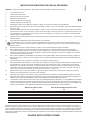
ENGLISH
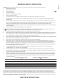
IMPORTANT SAFETY INSTRUCTIONS
WARNING: When using electrical products, basic cautions should always be followed, including the following:
1. Read these instructions.
2. Keep these instructions.
3. Heed all warnings.
4. Follow all instructions.
5. Do not use this apparatus near water.
6. Clean only with a dry cloth.
7. Do not block any of the ventilation openings. Install in accordance with manufacturer’s instructions.
8. Do not install near any heat sources such as radiators, heat registers, stoves or other apparatus (including amplifiers) that
produce heat.
9. Do not defeat the safety purpose of the polarized or grounding-type plug. A polarized plug has two blades with one wider than
the other. A grounding type plug has two blades and a third grounding plug. The wide blade or third prong is provided for your
safety. If the provided plug does not fit into your outlet, consult an electrician for replacement of the obsolete outlet.
10. Protect the power cord from being walked on or pinched, particularly at plugs, convenience receptacles, and the point they exit
from the apparatus.
11. Only use attachments/accessories provided by the manufacturer.
12. Use only with a cart, stand, tripod, bracket, or table specified by the manufacturer, or sold with the apparatus. When a cart is
used, use caution when moving the cart/apparatus combination to avoid injury from tip-over.
13. Unplug this apparatus during lightning storms or when unused for long periods of time.
14. Refer all servicing to qualified service personnel. Servicing is required when the apparatus has been damaged in any way, such
as power-supply cord or plug is damaged, liquid has been spilled or objects have fallen into the apparatus, the apparatus has
been exposed to rain or moisture, does not operate normally, or has been dropped.
15. Never break off the ground pin. Write for our free booklet “Shock Hazard and Grounding.” Connect only to a power supply of the
type marked on the unit adjacent to the power supply cord.
16. If this product is to be mounted in an equipment rack, rear support should be provided.
17. Note for UK only: If the colors of the wires in the mains lead of this unit do not correspond with the terminals in your plug‚
proceed as follows: a) The wire that is colored green and yellow must be connected to the terminal that is marked by the letter
E‚ the earth symbol‚ colored green or colored green and yellow. b) The wire that is colored blue must be connected to the
terminal that is marked with the letter N or the color black. c) The wire that is colored brown must be connected to the terminal
that is marked with the letter L or the color red.
18. This electrical apparatus should not be exposed to dripping or splashing and care should be taken not to place objects
containing liquids, such as vases, upon the apparatus.
19. The on/off switch in this unit does not break both sides of the primary mains. Hazardous energy can be present inside the
chassis when the on/off switch is in the off position. The mains plug or appliance coupler is used as the disconnect device, the
disconnect device shall remain readily operable.
20. Exposure to extremely high noise levels may cause a permanent hearing loss. Individuals vary considerably in susceptibility to
noise-induced hearing loss, but nearly everyone will lose some hearing if exposed to sufficiently intense noise for a sufficient
time. The U.S. Government’s Occupational Safety and Health Administration (OSHA) has specified the following permissible
noise level exposures:
Duration Per Day In Hours Sound Level dBA, Slow Response
8 90
6 92
4 95
3 97
2 100
11⁄2 102
1 105
1⁄2 110
1⁄4orless 115
According to OSHA, any exposure in excess of the above permissible limits could result in some hearing loss. Earplugs or protectors to
the ear canals or over the ears must be worn when operating this amplification system in order to prevent a permanent hearing loss, if
exposure is in excess of the limits as set forth above. To ensure against potentially dangerous exposure to high sound pressure levels, it is
recommended that all persons exposed to equipment capable of producing high sound pressure levels such as this amplification system be
protected by hearing protectors while this unit is in operation.
SAVE THESE INSTRUCTIONS!
Page is loading ...
Page is loading ...
Page is loading ...
Page is loading ...
Page is loading ...
Page is loading ...
Page is loading ...
Page is loading ...
Page is loading ...
Page is loading ...
Page is loading ...
Page is loading ...
Page is loading ...

Correct Disposal of this product. This marking indicates that this
product should not be disposed with other house hold wastes
throughout the EU. To prevent possible harm to the environment or
human health from uncontrolled waste disposal, recycle it responsibly
to promote the sustainable reuse of material resources. To return your
used device, please use the return and collection systems, or contact
the retailer where the product was purchased. They can take this
product for environmental safe recycling.
Logo referenced in Directive 2002/96/EC Annex
I(OJ(L)37/38,13.02.03 and dened in EN 50419: 2005
The bar is the symbol for marking of new waste and is applied
only to equipment manufactured after 13 August 2005
Forma correcta de deshacerse de este producto. Esta marca indica que este producto
no debe arrojarse junto con otros desperdicios domésticos en ningún lugar de la Unión
Europea. Para evitar posibles daños al medio ambiente o a la salud humana debidos a
desechos no controlados de desperdicios, recíclelo responsablemente para promover
la reutilización sostenible de los recursos materiales. Para devolver su dispositivo
usado, utilice los sistemas de devolución recolección, o contacte con el vendedor
minorista donde compró el producto. Ellos pueden llevar este producto al reciclado
seguro para el medio ambiente.
Logotipo al que se hace referencia en la Directiva 2002/96/EC
AnexoIV(OJ(L)37/38,13.02.03 y denido en EN 50419: 2005
La barra es el símbolo para marcar los nuevos desechos y se aplica
solamente a equipamiento fabricado después del 13 de agosto de 2005
Recyclez correctement ce produit. Cette signalisation indique que ce produit ne
doit pas être jeté avec les autres déchets domestiques dans les pays de l’UE. Pour
éviter toute atteinte à l’environnement ou à la santé humaine par des décharges
sauvages, recyclez ce produit de manière responsable pour encourager la
réutilisation durable des ressources matérielles. Pour retourner votre appareil usé,
veuillez utiliser les systèmes de collecte et de retour, ou contactez le revendeur
à qui vous avez acheté le produit. Il prendra en charge ce produit de manière à
protéger l’environnement.
Logo documenté dans l’annexe de la Directive 2002/96/EC
IV_(OJ(L)37/38,13.02.03 et déni par la norme EN 50419:2005
La barre est le symbole de signalisation des nouveaux déchets qui
s’applique uniquement aux équipements fabriqués après le 13 août 2005
Tuotteen oikea hävittäminen. Tämä merkki ilmaisee, että tuotetta ei saa hävittää muun
talousjätteen mukana EU:n alueella. Jotta estetään mahdolliset valvomattoman jätteiden
hävittämisen haitat ympäristölle tai ihmisten terveydelle, kierrätä tuote vastuullisesti ja
edistä materiaalien kestävää uudelleenkäyttöä. Voit palauttaa käytetyn laitteen käyttämällä
keräysjärjestelmiä tai ottamalla yhteyttä jälleenmyyjään, jolta laite ostettiin. He voivat
toimittaa tuotteen ympäristön kannalta turvalliseen kierrätykseen.
Logo viitattu direktiivin 2002/96/EY liitteen
IV(OJ(L)37/38,13.02.03 mukaisesti, määritelty standardissa EN 50419: 2005
Palkki on uuden jätteen merkintäsymboli ja sitä käytetään vain 13. elokuuta
2005 jälkeen valmistetuissa laitteissa
Juiste verwijdering van dit product. Deze markering geeft aan dat dit product
nergens in de Europese Unie met ander huishoudelijk afval mag worden afgevoerd.
Om mogelijke schade aan het milieu of gezondheid door ongecontroleerde
afvalverwijdering te voorkomen, recycle het op een verantwoorde wijze om het
duurzame hergebruik van materiaalgrondstoffen te bevorderen. Om uw gebruikte
apparaat in te leveren, kunt u gebruik maken van de inlever- en verzamelsystemen
of contact opnemen met de verkoper waar het product is gekocht. Zij kunnen dit
product innemen voor het milieuvriendelijk recycling.
Het logo waarnaar wordt verwezen in de bijlage van Richtlijn 2002/96/EG
IV(OJ(L)37/38,13.02.03 en omschreven in EN 50419: 2005
De balk is het symbool voor het markeren van nieuw afval en wordt
alleen toegepast op apparatuur dat is vervaardigd na 13 augustus 2005
正确处理此产品。此标志表明该产品在整个欧盟区内不应该与其他家居生
活废弃物一同处置。为防止因无控废弃物处置对环境或人类健康可能造成
的危害,请负责地回收并促进可重复使用的物质资源。要返还旧设备,请
使用退返收集系统,或联系购买此产品的零售商。他们会为环境安全回收
此产品。
标志参照 2002/96/EC 指令附录
IV(OJ(L)37/38,13.02.03 和 EN 50419: 2005 定义
条码符号标示新废弃物,仅适用于 2005 年 8 月 13 日后生产的设备
Entsorgen Sie dieses Produkt umweltgerecht. Diese Kennzeichnung bedeutet,
dass das Produkt innerhalb der EU nicht mit dem Hausmüll entsorgt werden darf.
Zur Vermeidung von Umwelt- und Gesundheitsschäden durch unkontrollierte
Entsorgung recyceln Sie das Gerät bitte. Geben Sie das Gerät an einer Sammelstelle
für Elektroaltgeräte ab oder wenden Sie sich an Ihren Fachhändler.
Logo eingetragen in Richtlinie 2002/96/EC AnhangI
IV_(OJ(L)37/38, 13.02.03 und deniert in EN 50419: 2005
Der Balken ist das Symbol zur Kennzeichnung neuen Abfalls und wird nur
auf Geräten angebracht, die nach dem 13. August 2005 gefertigt wurden
Korrekt bortskaffande av denna produkt. Denna märkning betyder att
produkten inte skall bortskaffas tillsammans med annat hushållsavfall i
hela EU. För att förhindra eventuella skador för miljön eller människors
hälsa från okontrollerat bortskaffande av avfall, återvinn det ansvarsfullt för
att främja hållbar återanvändning av materiella resurser. För att returnera
din använda enhet, använd återanvändnings- och uppsamlingssystem,
eller kontakta den återförsäljare där produkten köptes. De kan ta hand om
denna produkt för miljösäker återvinning.
Logotyp som hänvisas till i direktiv 2002/96/EG bilaga
IV(OJ(L)37/38,13.02.03 och denieras i EN 50419: 2005
Stapeln är symbolen för märkning av nytt avfall och är endast
tillämplig på utrustning som tillverkats efter 13 augusti, 2005
Corretto smaltimento di questo prodotto. Questo simbolo indica che questo prodotto
non deve essere smaltito insieme ad altri riuti domestici in tutta Europa. Per
prevenire possibili danni all’ambiente o alla salute umana dovuti allo smaltimento non
regolamentato dei riuti, è necessario riciclarlo responsabilmente al ne di promuovere
il riutilizzo sostenibile delle risorse materiali. Per restituire il dispositivo usato, utilizzare
i sistemi di restituzione e raccolta o contattare il rivenditore presso il quale il prodotto è
stato acquistato. Quest’ultimo può occuparsi del riciclaggio ambientale sicuro di questo
prodotto.
Simbolo presente nell’allegato IV_(OJ(L)37/38,13.02.03 della direttiva 2002/96/
CE e denito nello standard EN 50419: 2005
La barra è il simbolo indicante un nuovo riuto ed è applicata esclusivamente ad
apparecchiature prodotte successivamente al 13 agosto 2005

Features and specifications are subject to change without notice.
FCC Compliancy Statement
This equipment has been tested and found to comply with the limits for a Class A digital device,
pursuant to Part 15 of the FCC rules. These limits are designed to provide reasonable protection against
harmful interference when the equipment is operated in a commercial environment. This equipment
generates, uses and can radiate radio frequency energy and, if not installed and used in accordance
with the instruction manual, may cause harmful interference to radio communications. Operation of this
equipment in a residential area is likely to cause harmful interference in which case the user will be
required to correct the interference at his own expense.
Warning: Changes or modications to the equipment not approved by Peavey Electronics Corp. can
void the user’s authority to use the equipment.
Peavey Electronics Corporation • 5022 Hartley Peavey Drive • Meridian, MS • 39305
(601) 483-5365 • FAX (601) 486-1278 • www.peavey.com

PVX
™
p Sub
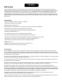
Thank you for purchasing the powered Peavey
®
PVX
™
p Sub. The PVXp Sub
features an ultra-reliable power section that
provides a total of 800 watts of peak available power with DDT
™
compression. This powered enclosure also features a 15”
heavy-duty woofer with a 3" voice coil. The PVXp Sub
provides a balanced input via a combination jack that accepts balanced
TRS 1/4" input as well as a balanced XLR input. There are two balanced thru high pass XLR outputs, and a Full-Range XLR
output. There is an adjustable Level control, as well as a combination LED indicator, that illuminates when power is on and
when the “soft-limiting” DDT circuit is activated.
Features
• Vented bass powered subwoofer enclosure
• 800 watts peak available power
• 15” heavy-duty woofer
• Power Amp has forced air cooling for maximum reliability
• Internal line level low-pass/high-pass crossover network
• Fully adjustable Kosmos
®
C for increased bass impact
• XLR/1/4" combo jack input
• Two high-pass XLR outputs, and one full-range thru XLR output
• Polarity switch for polarity reversal of subwoofer
• Ground lift for lifting cable shield from ground
• Large heavy-duty locking casters with damped bearings
• Full-coverage heavy-duty perforated steel grill
• Steel handles
• Compact dimensions for a 15” woofer based sub
• Threaded pole mount with speaker pole included
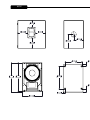
DESCRIPTION
The Peavey
®
PVXp
Sub is a compact, vented, powered subwoofer system utilizing a 15” heavy-duty woofer, coupled to a
power amplifier, with 800 watts peak available power. The full-length black perforated steel grille provides protection and a
professional appearance, along with the sturdy steel handles and heavy-duty 4” tall casters for transport.
Internal line-level crossover with two high-pass outputs, independently electrically buffered; and one full-range thru output,
also electrically buffered.
Peavey’s exclusive Kosmos
®
C bass enhancer for extra bass punch from very low frequency program material is incorporated
for maximum versatility.
A threaded pole-mount system provides a sturdy and stable platform to mount a suitably equipped speaker system above the
sub woofer. The PVXp two-way powered speaker series are an excellent partner for the PVXp Sub.
The PVXp Sub speaker system power amplifier providing the power is a low-distortion ultra-reliable fan-cooled unit providing a
total of 800W peak available power for the system. The power supply for the power amp is a switch-mode type for low weight
and high efficiency. The amplifier features our DDT
compression, which virtually eliminates audible power amplifier clipping.
Cooling is provided via a low-noise fan, for reliable operation under any conditions.
Input is via a combo female XLR and 1/4” TRS phone jack with balanced input to the preamp/EQ electronics, and a level
control.
An independent pair of High-Pass Outputs provides a buffered and balanced output signal for a pair of satellite speakers to
carry the high range of the music, via a pair of male XLR jacks.
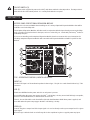
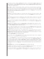
ENGLISH

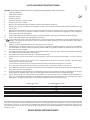
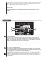
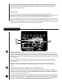
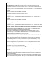
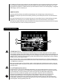
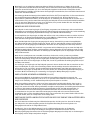
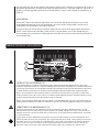
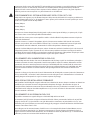
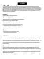
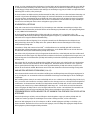
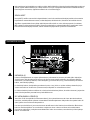
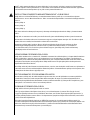
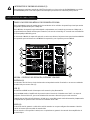
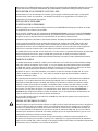
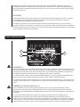
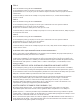
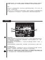
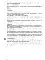
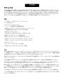
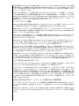
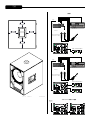
CIRCUIT BREAKER (1)
The unit is AC power line protected from overloads and fault conditions with a 5 amp circuit breaker. This
breaker should not trip unless there is a fault in the amplifier circuitry or an abnormal operating condition,
which causes excessive mains current to flow. If the breaker trips, set the Power switch (3) to OFF, and after
waiting a brief period of time for the breaker to cool, reset the breaker.
If the circuit breaker trips, the center button will pop outward approximately 1/4”, and can be reset by pushing
upward and inward. Under normal (not tripped) conditions, the center button is relatively flat.
If the unit continues to trip the breaker, or trips it immediately after being reset, do not keep resetting it, the
system should be taken to a qualified Peavey Service Center for repair.
IEC POWER CORD CONNECTION (2)
This receptacle is for the IEC line cord (supplied) that provides AC power to the unit. It is very important that
you ensure the PVXp Sub has the proper AC line voltage supplied. You can find the proper voltage for your PVXp
Sub printed next to the IEC line (power) cord on the rear panel of the unit.
Please read this guide carefully to ensure your personal safety as well as the safety of your equipment. Never
break off the ground pin on any equipment. It is provided for your safety. If the outlet used does not have a
ground pin, a suitable grounding adapter should be used and the third wire should be grounded properly. To
prevent the risk of shock or fire hazard, always be sure that the mixer and all other associated equipment are
properly grounded.
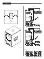
REAR PANEL BOTTOM
A Full-Range Thru output has a male XLR connector. These outputs allow linking of additional speaker systems,
or feed of the signal to other devices, etc. Included in the input panel is a bay for optional function modules,
such as a Wireless Receiver, Digital Audio Input or a 10-band EQ, etc.
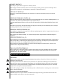
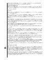
APPLICATIONS
The Peavey PVX
™
p Sub has a variety of applications, such as extending the bass performance of smaller
full-range speaker systems for sound reinforcement, public address, side fill system, karaoke or musical
playback.
A typical signal source for the line-level inputs of the Peavey PVXp Sub would be a sound reinforcement mixing
console (mixer) or the output from a CD player, MP3 player or tape deck. The high-pass filtered signal from the
PVXp Sub would then be sent to a full-range powered speaker system, easing the burden of deep bass from this
speaker system.
1
3
2

ON-OFF SWITCH (3)
This rocker switch supplies AC power to the
PVX
™
p
Sub when switched to the ON position. The ON position is
with the left side of the switch pushed “in” or nearly flush with the rear panel.
ACCESS PANEL FOR OPTIONAL EXPANSION MODULE
This panel is to be removed ONLY when installing one of a variety of Optional Expansion Modules that will be
available soon for the PVXp Sub.
These Optional Expansion Modules will either work in conjunction with the input already present on the PVXp
Sub, or provide an in-line function for the input, such as a 10-band EQ, etc. Check with your Peavey
®
dealer for
availability and price.
If you are not installing such an Optional Expansion Module, then do not remove this cover, instructions for
installing an Optional Expansion Module will come with each Expansion Module and will be specific for that
Module.
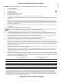
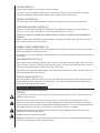
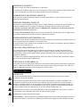
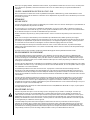
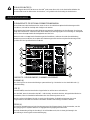
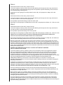
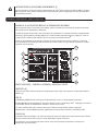
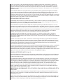
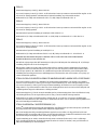
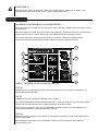
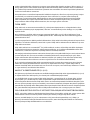
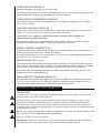
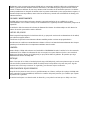
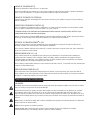
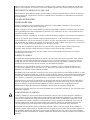
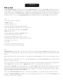
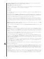
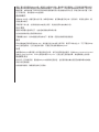
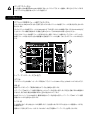
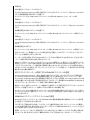
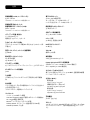
TOP – OPERATING CONTROLS, INPUTS & OUTPUTS
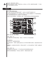
INPUT (4)
The line-level input is of the medium impedance balanced type. The jack is a combo female XLR and 1/4" TRS
connector.
LED (5)
Illuminates GREEN when the power switch is on and power is present
It turns RED when the power amp engages the DDT
™
“soft limiting” circuitry. Occasional flashing is acceptable,
but not a constant illumination, or distortion will be excessive.
There is also an LED visible on the front baffle of the Sub that illuminates BLUE when power is applied, and
turns RED when the power amp engages the DDT
“soft limiting” circuitry.
LEVEL (6)
Controls the gain or output level of the input signal. It is used to directly set the system output level for a given
input signal.
Normal usage is with the knob set to half-way, this is then equivalent in gain to a typical power amp input.
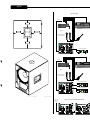
REAR PANEL TOP
5
6
4
7
8
13
9
10
11-12

OPERATING INSTRUCTIONS
POLARITY SWITCH (7)
Provides either 0 degrees or 180 degrees sub woofer polarity
This switch is used on conjunction with the Crossover Frequency Control (9) to provide for the best match
between the Subwoofer output and the satellite speaker output in the crossover region.
GROUND LIFT SWITCH (8)
Provided for lifting cable shield from chassis ground, to break potential ground loops and reduce hum.
CROSSOVER FREQUENCY CONTROL (9)
Varies the crossover frequency between the Subwoofer and the High Pass Outputs sent to the satellite/s
speaker/s (11 & 12). Varies the electrical crossover frequency from 90 Hz to 180 Hz.
CAUTION! SETTING THIS CONTROL TOO LOW MAY ALLOW THE SATELLITE SPEAKER TO BE OVERLOADED BY
DEEP BASS!
Setting the control lower DOES NOT increase the deep bass output of the PVX
™
p
Sub, a middle (12 o'clock) to
higher setting works best for most speakers.
KOSMOS
®
C BASS ENHANCEMENT (10)
Provides the capability to add bass harmonics to enhance the perception of deep bass in the program material
without overloading the Subwoofer speaker.
This control is best used in moderation, and turning it full up can cause the program material to sound distorted
or unnatural.
HIGH PASS OUTPUTS (11 & 12)
These outputs provide a high-pass filtered signal to be fed to a full-range powered speaker system, such as the
PVXp
10, PVXp
12 or PVXp
15. Other full-range powered speakers can be used, and full-range passive speakers
can be used in conjunction with a suitable power amp to drive them.
These outputs are electronically buffered and isolated from the input and from each other, and their level is not
affected by the PVXp Sub Level control (6).
THRU FULL RANGE OUTPUT (13)
This output provides a full-range signal to be sent to any other device that requires a full-range signal, such as
another PVXp Sub, or some other line level audio device. This output is electronically buffered and isolated
from the input and from the other outputs.
CAUTIONS
The unit must be disconnected from the AC power source before any work is done on it. Refer all servicing to
qualified service personnel.
The back plate can become hot to the touch. Do not block or cover the fan or the exhaust louvers from
ventilation. There must be a minimum of 4” of space behind the fan. Do not allow the airflow to be become
blocked by objects such as curtains or drapes, thermal building insulation, etc. It is recommended that the rear
of the PVXp Sub not be placed in a closed space or a space that has no fresh, cool airflow.
DO NOT connect the inputs of the PVXp Sub to the output of a power amplifier. The inputs are meant to be
driven from a line-level strength signal.
DO NOT remove the protective metal grilles.
WARNING! The PVXp Sub is very efficient and powerful! This sound system can permanently damage hearing!
Use extreme care setting the overall maximum volume!

The apparent sound level of the PVX
™
p
Sub can be deceiving due to its clear, clean sound output and lack of
high frequencies. The lack of distortion or obvious distress can make the sound level seem much lower than it
actually is. This system is capable of SPL in excess of 127 dB at 1 M from the speaker!
PLACING A SATELLITE SPEAKER SYSTEM ON TOP OF THE PVX
™
p SUB
The PVXp Sub has a threaded pole mount built-in to the top of the unit, and this is designed to mate with an
M20 threaded pole of approximately 32” in length or less. This pole is specifically designed to be used with the
following speaker systems:
Peavey PVXp 10
Peavey PVXp 12
Peavey PVXp 15
Do not place a taller/larger or heavier speaker system than the PVXp
15 on this pole, or it may be unsafe due to
the potential to tip over.
The PVXp Sub must be placed on firm and level ground, in order for the pole mounted speaker to be safe from
tipping.
When installing or de-installing the speaker on the pole, it is a good practice to have a helper, if possible. It can
be hard to “thread the needle” and mate the pole cup to the Subwoofer pole while holding the speaker system
at arm’s length.
When using the PVXp Sub and pole outdoors, never attach banners or flags to the pole or the pole mounted
speaker system, strong winds may cause the speaker to blow over. If there is a possibility of strong windy
conditions, then it may be prudent to consider removing the speaker from the pole to prevent the PVXp Sub and
pole mounted speaker system from being blown over.
CONNECTING AC POWER TO THE PVXp SUB
The PVXp Sub comes with a 6-foot IEC connection AC power cord. If you are using an extension cord or power
strip with this powered speaker, make sure it is of good quality and of a sufficient current capacity to maintain
safety and maximize the power output capability of the PVXp Sub. For maximum undistorted output, do not
connect any other device to the same extension cord that the PVXp
Sub is connected to. Do not exceed the
rated current capacity of the extension cord with the sum total of all units connected to it.
When first plugging in the PVXp Sub AC cord, make sure the power switch is in the Off position, and then turn
it On only after connecting the power cord. Built-in muting will engage, when the proper sequence of steps is
taken.
SPECIAL NOTE FOR PERMANENT INSTALLATION
When installing the PVXp Sub, AC power runs will be used and a certified electrician should be consulted, to be
sure that all AC wiring complies with local codes and regulations. It is also advisable to use a cable clip properly
affixed to the cabinet to strain relief the IEC power cord connected to the amplifier module at (2) so the power
cord cannot be pulled out or vibrate loose.
CONNECTING A SIGNAL TO THE PVXp SUB
There are a variety of ways to input a signal into the PVXp Sub.
The input (4) provides a balanced line-level input, allowing the use of a 1/4" TRS (ring-tip-sleeve) type phone
plug or a male XLR plug. Of course, an unbalanced 1/4" phone plug can be used as well, but it will not have the
benefit of the balanced connections rejection of outside interference, such as hum and RFI.
Do not connect cables to the jacks while the unit is ON and the Level knob is turned up! While a standard
single-ended 1/4" phone plug-equipped cable will work well and the balanced input circuitry will provide some
interference rejection, a balanced cable using either the balanced TRS 1/4" phone plug or the XLR plug will
provide superior interference rejection and performance.

Sometimes, with difficult interference problems, it will be helpful to lift the shield ground ( Pin #1 of an XLR)
of a balanced cable at the PVX
™
p Sub end. This can be done quite easily, by activating the Ground Lift switch
(10) built into the PVXp Sub. Check any input changes carefully, always turning the Level control down before
plugging and unplugging cables, or lifting the ground.
Use of high quality, premium cables is recommended for the PVX
™
p Sub, as these usually have better shielding
and materials and will provide greater long-term reliability. The best option is a shielded balanced cable no
longer than necessary to reach the PVXp Sub. It is usually a good idea to leave some slack at the input to the
PVXp Sub and also to tape the cables down or run them under a cable guard, to avoid anyone tripping over them
or pulling the PVXp Sub over when it is holding a speaker on top of it’s pole.
LEVEL CONTROL ADJUSTMENT
The PVXp Sub is equipped with a Level control (6) on the input to facilitate use in many different applications.
With the Level control adjusted fully clockwise, gain is at maximum and the input sensitivity is 0.24 V RMS for
full-rated output.
It is recommended that the PVXp Sub Level control be set close to 12 o'clock position, or 0 dB preamp gain. At
this setting, the input sensitivity is approximately 2.4 volts RMS for full-rated output. The PVXp Sub will now
more closely match a typical power amp input.
If the mixing board indicates clipping of its output signals, then all of the PVXp Sub power capability is not
being utilized cleanly. Clipping the signal before it gets to the PVXp Sub is not optimal. Reduce the mixer
output level and turn up the Level control on the PVXp Sub.
The amplifier in the PVXp Sub is equipped with DDT
™
and the LED indicator will show when PVXp Sub DDT
has engaged. If the sound seems heavily compressed, check these indicators; if it is blinking RED more than
occasionally, then the drive level from the mixer (or the Level control on the PVXp Sub) needs to be reduced.
When first turning on the sound system, switch on all upstream electronics first, then the PVXp Sub with its
Level control fully counterclockwise (all the way down). Begin checking levels with the mixer output level
controls all the way down, and bring them up slowly with the PVXp Sub Level control set to the desired setting
(one-half way up recommended to start).
It is not good practice to turn the Level control on the PVXp Sub all the way up and then try to control level only
from the mixer, this approach would tend to pick up excess noise. Best practice would be to run a “hot” signal
from the mixer down the cable to the PVXp Sub, and then turn the PVXp Sub Level control up only as much
as necessary to reach full desired output. With this approach, it is necessary to verify the mixer output is not
clipping.
CABLES FROM THE HIGH PASS OUTPUTS (11 & 12)
The preferred method of connecting a full-range satellite speaker system to the PVXp Sub’s High Pass Outputs
(11 & 12), is to use a balanced XLR cable no longer than necessary to comfortably reach the satellite speaker
system.
If the satellite speaker is on top of a pole above the PVXp Sub, then a 6 foot cable will be plenty long. A 10,
or 20 foot cable could also be used, but cables longer than that will only allow more interference pickup, and
start to lose high-frequency information. Use of high quality, premium cables is recommended for the PVXp
Sub, as these usually have better shielding and materials and will provide greater long-term reliability. . It is
usually a good idea to leave some slack at the output of the PVXp Sub, and also to tape the cables down or run
them under a cable guard to avoid anyone tripping over them or pulling the PVXp Sub over when it is holding a
speaker on top of it’s pole.
RECOMMENDED SETTINGS FOR USE OF THE PVXp SUB WITH THE PVXp
SERIES POWERED
SPEAKERS
The ideal location for placement of the powered PVX
™
p
series full-range speakers is on top of the PVXp Sub
pole. In that close proximity, the following settings will provide the best results in the crossover region, and for
tonal balance.
Note that the XLR outputs (11 & 12), have been padded 12 dB to allow the XLR inputs on the PVXp
12 and PVXp
15 to be used. Normally, these are considered the mic level inputs, but with the PVXp Sub outputs padded, the
usage of the XLR inputs on the PVXp powered speakers is possible.

PVXp
10
Polarity Switch on Sub (7): Normal or IN
Crossover Frequency Control (9): From 12 o'clock to full clockwise. This represents a range from approximately
110 Hz to 160 Hz for the crossover point. Recommended optimal setting is full clockwise position.
Level Controls (6): PVXp
™
Sub Level control at 12 o'clock (0 dB), PVXp10 Level control at 12 o'clock
PVXp
12
Polarity Switch on Sub (7): Normal or IN
Crossover Frequency Control (9): From 12 o'clock to full clockwise. This represents a range from approximately
110 Hz to 160 Hz for the crossover point.
Recommended optimal setting is set to two tics past 12 o'clock.
Level Controls (6): PVXp
sub Level control at 12 o'clock (0 dB), PVXp
12 Level control at - 2 tics before 12 o'clock
PVXp
15
Polarity Switch on Sub (7): Normal or IN
Crossover Frequency Control (9): From 12 o'clock to full clockwise. This represents a range from approximately
110 Hz to 160 Hz for the crossover point.
Recommended optimal setting is set to 12 o'clock.
Level Controls (6): PVXp Sub Level control at 12 o'clock (0 dB), PVXp
12 Level control at - 2 tics before 12 o'clock
CAUTION! SETTING THE CROSSOVER FREQUENCY CONTROL TOO LOW MAY ALLOW THE SATELLITE SPEAKER TO
BE OVERLOADED BY DEEP BASS AT HIGH SPL !
Setting the control lower DOES NOT increase the deep bass output of the PVXp Sub, a middle (12 o'clock) to
higher setting works best for most speakers.
If the PVXp
series speakers are not set on top of the Subwoofer on the pole, then the polarity switch settings
may need to be different than what is provided here. The Crossover Frequency Control may need to be set to a
lower point in order for the Subwoofer and the satellites to sum well through the crossover region. The settings
outlined above will work the best when the satellite speaker and the Subwoofer are closer together, and
essentially the same distance from the audience.
SETTING THE PVXp SUB CONTROLS FOR USE WITH OTHER SATELLITE SPEAKERS
Crossover Frequency Control (9): In general, for smaller full-range speakers to be used as satellites, set the
Crossover Frequency Control (9) to a higher frequency setting. For larger full-range speakers, set the Crossover
Frequency Control (9) to a lower frequency setting. Setting the Crossover Frequency Control very much below
the 12 o'clock position will not be needed most of the time, as a crossover frequency below 100 Hz is not going
to allow the PVXp Sub and the satellite speaker to add together very well in the crossover region.
Polarity Switch (7): Try changing the Polarity Switch setting back and forth at each selected crossover frequency,
so as to determine which switch position provides the most bass output in the crossover region
Level Controls (6): Start with the PVXp Sub Level control in the 12 o'clock position, and adjust the satellite
speaker system to match it’s level. Note that if the Subwoofer can be heard as a distinctly separate sound
source, then it is probably set too high in level.
SETTING THE KOSMOS
®
C BASS ENHANCE CONTROL (10)
The Kosmos
®
C Bass Enhance control can add apparent bass extension and output to the reproduced sound,
especially when the program material has significant content below the PVXp Sub’s cut-off frequency.
When appropriate, judicious use can enhance the enjoyment of the music, and add punch and boom to the mix.
However, setting the control to higher than optimal level can result in a perception of noticeable distortion or
less clear bass sounds. Seldom will it be helpful to turn the control all the way up.
Typical use will involve a setting of the control knob somewhere between Off (full counter clockwise) and 12
o'clock (half-way up). Then the added effect is more subtle and less intrusive during certain moments in the
music, while still providing a welcome enhancement of the overall sound.

Note that at extreme full clockwise settings, the effective gain of the Subwoofer is increased, so if it was on the
verge of clipping before, turning the Bass Enhance Control way up may cause it to go into clipping.
DISCONNECTING AC POWER TO THE PVX
™
p SUB
We recommend that the Power switch (3) be used to turn the unit off first, and then the AC power cord can be
removed, this minimizes stress to the power amplifiers and the transducers from turn-off transients. The power
switch has an arc suppression capacitor to help during turn-off, and tends to make a clean disconnect from
the AC power, while the power cord IEC connector can make intermittent contact before finally becoming fully
disconnected, e.g., as when wiggling the cord.
TROUBLESHOOTING
NO OUTPUT AT ALL
First, make sure the unit has AC power and is turned ON. Make sure the LED on the power amp module is
illuminated.
If not, make certain the ON/OFF switch (3) is in the ON position and check the IEC power cord connection (2) by
ensuring it is fully engaged and seated. Make certain the AC line cord is plugged into a working AC outlet.
Finally, check the breaker (1). (See the Rear Panel: Breaker section, for safety instructions.)
Once assured your unit is getting AC power, check that the PVX
™
p
Sub is getting a signal. Temporarily
disconnect the cable running to its inputs and connect it to some other device capable of reproducing the signal
(i.e., a power amp and speaker). If this produces a signal, make sure that all Level controls being used have
been turned up to a satisfactory level (one-third to halfway).
If the PVXp Sub has been subjected to direct sunlight or excessive heat, the built-in thermal protection may
have been triggered. If so, turn off the PVXp Sub and let it cool for a sufficient amount of time.
If there is still no output, contact your authorized Peavey dealer or the Peavey International Service Center.
HUM OR BUZZ
If the PVXp Sub is producing a hum or buzz, this can be AC outlet related. Try plugging the PVXp Sub into a
different AC outlet. Sometimes, if a different circuit (breaker) is used for the mixer and for the PVXp Sub, it can
cause hum problems. Unless it is not practical, it is best to use the same wall outlet (breaker) to supply power
to both the mixer and the powered speaker.
Ensure that shielded cables have been used to route the signal to the PVXp Sub’s input. If speaker cables with
1/4" plugs are used as input cables instead of shielded cables, they will be prone to hum or buzz.
Hum may be ground loop related. It may be helpful to lift the shield ground (Pin #1) on a balanced cable at
the PVXp Sub end. This is done quite easily by activating the Ground Lift switch (10) built-in to the PVXp Sub.
Check any input changes carefully by first turning down the Level control, before plugging and unplugging
cables, or lifting the shield ground at the Sub.
Check to make sure light dimmers are not on the same circuit as the PVXp Sub, the mixer or any source devices.
If light dimmers are used, then it may be necessary to turn them full ON or full OFF to eliminate or reduce hum.
This is a typical AC wiring/light dimmer interference problem, not a design flaw of the PVXp Sub.
The third wire (ground plug) on the AC plug should NEVER be removed or broken off, as this is a potential safety
hazard.
DISTORTED OR FUZZY SOUND
First, ensure the mixer (signal source) is not clipping or being overdriven. Make sure the Level (6) control on the
PVXp Sub has not been set too low. Check that the input plug is fully seated in the input jack on the rear panel
of the PVXp Sub. Ensure that a power amp has not been plugged into the input jack of the PVXp Sub. If an
extension cord is being used to provide the AC power to the unit, ensure that it is of sufficient current capacity
and that it is not also being used to supply power to any other device.
The PVXp Sub has a built-in bass boost to extend and smooth the natural response of the speakers in the
system, so it should require little, if any, additional EQ. If excessive additional bass boost have been added
externally to the PVXp Sub, it could cause premature overload at high SPL. Reduce the amount of any external
(mixer, rack) EQ and see if that clears up the distortion.

Finally, realize that even though the PVXp Sub is a powerful and high output unit, it does ultimately have limits,
and it may need additional powered Subwoofer units to provide enough sound output or coverage. In this case,
try turning the mixer levels down a little to see if that clears things up. If, after checking all the things listed to
check and anything else you can think of to check safely, and the system still exhibits problems, carefully note
all conditions and check with your Peavey dealer for advice.
CARE AND MAINTENANCE
Your PVXp Sub is a sturdy and durable product and will provide years of reliable use if properly cared for. Use
common sense and read the safety warnings to avoid hazardous operating conditions.
The unit must be disconnected from the AC power source before any work is done on it. Refer all servicing to
qualified service personnel.
SUNLIGHT/HEAT
Avoid prolonged exposure to direct sunlight, as this may cause the unit to overheat and thermally shut off.
Excessively hot operating conditions can also cause a thermal shutdown.
Do not store in extremely hot or cold conditions or extremely high humidity. Always allow unit to come to
room temperature before use.
CLEANING
Never clean the PVXp Sub while plugged in or turned ON! When the unit has been fully disconnected from
AC power sources, use a dry cloth to remove soil or other dirt. Never use strong solvents on the PVXp Sub,
as they could damage the cabinet. Do not allow ANY fluids to drip inside the PVXp Sub.
TOUCH-UP
For a touch-up of any damage to the black painted finish of the PVXp Sub, you can use a black spray paint
such as Peavey Commercial Sound, Black Touch-Up Paint, Peavey part number 00052110. Follow the
directions on the can for safety and best results.
CHECK FOR SECURE HARDWARE
After the first few months of use and periodically thereafter, check the hardware of the PVXp Sub for
tightness, including the rear panel screws and the screws that hold the grille and cabinet together.
The unit is subject to a great deal of vibration, and this could cause them to loosen with use.
Features and specifications are subject to change without notice.
Peavey Electronics Corporation • 5022 Hartley Peavey Drive • Meridian • MS • 39305
(601) 483-5365 • FAX (601) 486-1278 • www.peavey.com • ©2013 • EX000178
Page is loading ...

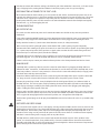
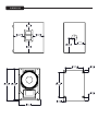
23.681
601.50
16.749
425.41
24.172
613.96
11.500
292.10
8.375
212.71
8.648
219.66
8.667
220.14
8.648
219.66
5.667
143.94
8.667
220.14
8.648
219.66
8.648
219.66
5.667
143.94
14.067
357.30
18.486
469.54
1.341
34.06
1.591
40.41
2.923
74.25
1:3.5
RBT
XXX
RBT
SEE PARTS,
CABINET ASSEMBLY
REV
REVISION DESCRIPTION
ZONE
BY
CHK'D
ECN
DATE
DRAWN
DATE
CHK'D
SCALE
MECH.
ENGR.
UNLESS OTHERWISE SPECIFIED,
THE FOLLOWING APPLY:
TOLERANCES:
.XXX =
.005 INCHES
ANGLES =
0.5°
MATERIAL:
FINISH:
DESC.
PEAVEY ELECTRONICS CORP.
P.O. BOX 2898
MERIDIAN, MS 39301
DWG NO.
REV.
A
SHEET 1 OF 1
P1203301D
1/17/2013
R
8
7
6
5
4
3
2
1
1
2
3
4
5
6
7
8
A
B
C
D
E
F
G
G
F
E
D
C
B
A
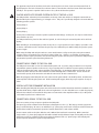
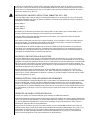
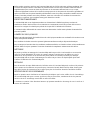
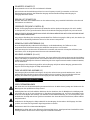
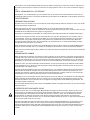
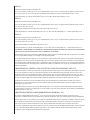
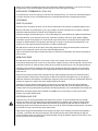
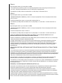
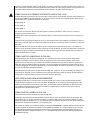
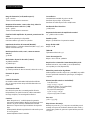
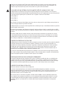
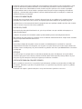
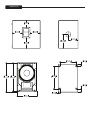
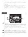
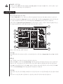
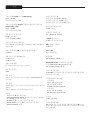
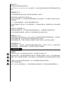
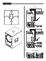
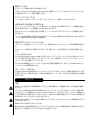
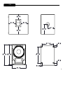
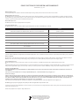
DIMENSIONS
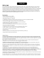
PVXp 12 or PVXp 15
PVXp 12 or PVXp 15
Dynamic Mic
(No Electrets)
Output Inputs
Keyboard
Mixer
Guitar
PVXp 12 or PVXp 15
Dynamic Mic
(No Electrets)
Output Inputs
Keyboard
Mixer
Guitar
Input to
1st Sub
Daisy-Chain Connection (Multiple Subs)
Typical Usage

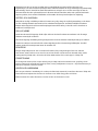
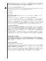
SPECIFICATIONS
Frequency Range (-10 dB, Half Space):
43 Hz – 180 Hz*
*Crossover Control Full CW
Frequency Response, 1 Meter On-axis, Swept-sine In
Anechoic Environment (-6 dB):
48 Hz – 138 Hz*
*Crossover Control Full CW
Power Amp Rating, Total Power Output:
800 watts peak available power
Continuous Power: 470 watts into 4 ohms
Electronic Input Impedance (Nominal):
Line In: 2.2 k ohms balanced (XLR or 1/4"), 10 k ohms
unbalanced 1/4"
Sound Pressure Level, 1 Watt, 1 Meter In Anechoic
Environment:
97 dB SPL
Maximum Sound Pressure Level (1 meter):
123 dB SPL continuous
127 dB SPL peak
Transducer Complement:
15" premium heavy-duty woofer, 3" voice coil
Box Tuning Frequency:
50 Hz
Input Connections:
One combo female XLR/ 1/4" phone jack providing balanced
or unbalanced operation.
Output Connections:
Two High Pass Outputs, independently electrically buffered,
with switchable output level pad.
One Full Range Thru, electrically buffered.
Controls:
Level: Provides +/- 20 dB gain adjustment
Crossover Frequency Adjust: Adjusts electrical crossover
frequency from 90 Hz to 180 Hz, continuously variable.
Kosmos
®
C: Provides bass enhancement processing.
Polarity Switch: Provides either 0 degrees or 180 degrees
sub woofer polarity
Ground Lift Switch: For input
Electronic Crossover
Continuously variable from 90 Hz to 180 Hz.
Low Pass slope: 24 dB/octave
High Pass Output slope: 18 dB/octave
Infrasonic Filter Slope:
36 dB/octave
Nominal Amplifier Frequency Response:
+0, -3 dB from 20 Hz to 20 kHz
Hum and Noise:
Greater than 90 dB below rated power
DDT Dynamic Range:
Greater than 21 dB
THD and IM:
Typically less than 0.5 %
Damping Factor:
Greater than 100 @ 1000 Hz, 4 Ohms
Power Requirements Of Peavey PVX
™
p Sub System:
Nominal 160 Watts, 100-120 VAC 50-60 Hz (Domestic)
220-240 VAC 50-60 Hz (Export)
Enclosure Materials & Finish:
Black acrylic painted enclosure with 15 mm MDF, with a
full-length, black powder coated perforated steel grille.
DImensions (H x W x D)
In use position:
24.25" x 16.75" x 23.00"
(not including wheels, 4.06” deep)
616 mm x 425 mm x 584 mm
In transport position:
27.06" x 16.75" x 24.25"
687 mm x 425 mm x 616 mm
Net Weight:
76.Lbs. (34.5 kg)
Mounting Provisions:
1 3/8" pole mount with M20 threaded pole for stand
mounting a suitable speaker on top of the Sub, and four large
rubber feet on bottom for floor use.
Page is loading ...
Page is loading ...
Page is loading ...
Page is loading ...
Page is loading ...
Page is loading ...
Page is loading ...
Page is loading ...
Page is loading ...
Page is loading ...
Page is loading ...
Page is loading ...
Page is loading ...
Page is loading ...
Page is loading ...
Page is loading ...
Page is loading ...
Page is loading ...
Page is loading ...
Page is loading ...
Page is loading ...
Page is loading ...
Page is loading ...
Page is loading ...
Page is loading ...
Page is loading ...
Page is loading ...
Page is loading ...
Page is loading ...
Page is loading ...
Page is loading ...
Page is loading ...
Page is loading ...
Page is loading ...

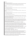
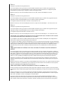
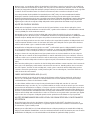
DIMENSIONI
PVXp 12 o PVXp 15
PVXp 12 o PVXp 15
Mic dinamico (non
elettrorete)
Uscita Ingressi
Tastiera
Mixer
Chitarra
PVXp 12 o PVXp 15
Mic dinamico (non
elettrorete)
Uscita Ingressi
Tastiera
Mixer
Chitarra
Ingresso al
1° Sub
Connessione Daisy-Chain (più sub)
Utilizzo tipico
23.681
601.50
16.749
425.41
24.172
613.96
11.500
292.10
8.375
212.71
8.648
219.66
8.667
220.14
8.648
219.66
5.667
143.94
8.667
220.14
8.648
219.66
8.648
219.66
5.667
143.94
14.067
357.30
18.486
469.54
1.341
34.06
1.591
40.41
2.923
74.25
1:3.5
RBT
XXX
RBT
SEE PARTS,
CABINET ASSEMBLY
REV
REVISION DESCRIPTION
ZONE
BY
CHK'D
ECN
DATE
DRAWN
DATE
CHK'D
SCALE
MECH.
ENGR.
UNLESS OTHERWISE SPECIFIED,
THE FOLLOWING APPLY:
TOLERANCES:
.XXX =
.005 INCHES
ANGLES =
0.5°
MATERIAL:
FINISH:
DESC.
PEAVEY ELECTRONICS CORP.
P.O. BOX 2898
MERIDIAN, MS 39301
DWG NO.
REV.
A
SHEET 1 OF 1
P1203301D
1/17/2013
R
8
7
6
5
4
3
2
1
1
2
3
4
5
6
7
8
A
B
C
D
E
F
G
G
F
E
D
C
B
A
Page is loading ...
Page is loading ...
Page is loading ...
Page is loading ...
Page is loading ...
Page is loading ...
Page is loading ...
Page is loading ...
Page is loading ...
Page is loading ...
Page is loading ...

MÅTT
PVXp 12 eller PVXp 15
PVXp 12 eller PVXp 15
Dynamisk Mic (Ingen
elektret)
Utgångar Ingångar
Keyboard
Mixer
Gitarr
PVXp 12 eller PVXp 15
Dynamisk Mic (Ingen
elektret)
Utgångar Ingångar
Keyboard
Mixer
Gitarr
Ingång till
1:a sub
Daisy-Chain-anslutning (era subs)
Typisk användning
5%7
;;;
5%7
6((3$576
&$%,1(7$66(0%/<
5(9
5(9,6,21'(6&5,37,21
=21(
%<
&+.'
(&1
'$7(
'5$:1
'$7(
&+.'
6&$/(
0(&+
(1*5
81/(6627+(5:,6(63(&,),('
7+()2//2:,1*$33/<
72/(5$1&(6
;;;
,1&+(6
$1*/(6
0$7(5,$/
),1,6+
'(6&
3($9(<(/(&7521,&6&253
32%2;
0(5,',$106
':*12
5(9
$
6+((72)
3'
5
$
%
&
'
(
)
*
*
)
(
'
&
%
$
Page is loading ...
Page is loading ...
Page is loading ...
Page is loading ...
Page is loading ...
Page is loading ...
Page is loading ...
Page is loading ...
Page is loading ...
Page is loading ...
Page is loading ...
Page is loading ...
Page is loading ...
Page is loading ...
Page is loading ...
Page is loading ...
Page is loading ...
Page is loading ...
Page is loading ...
Page is loading ...
Page is loading ...
Page is loading ...
Page is loading ...
Page is loading ...
Page is loading ...
Page is loading ...
Page is loading ...
Page is loading ...
Page is loading ...
Page is loading ...
Page is loading ...
Page is loading ...
Page is loading ...
Page is loading ...
Page is loading ...
Page is loading ...
Page is loading ...
Page is loading ...
Page is loading ...
Page is loading ...
Page is loading ...
Page is loading ...
Page is loading ...
Page is loading ...
Page is loading ...
Page is loading ...
Page is loading ...
Page is loading ...
Page is loading ...
Page is loading ...
Page is loading ...
Page is loading ...
Page is loading ...
Page is loading ...
Page is loading ...
Page is loading ...
Page is loading ...
Page is loading ...
Page is loading ...
Page is loading ...
Page is loading ...
Page is loading ...
Page is loading ...
Page is loading ...
Page is loading ...
Page is loading ...
Page is loading ...
Page is loading ...
Page is loading ...
Page is loading ...
Page is loading ...
Page is loading ...
Page is loading ...
Page is loading ...

PEAVEY ELECTRONICS CORPORATION LIMITED WARRANTY
Effective Date: 09/15/2010
What This Warranty Covers
Your Peavey Warranty covers defects in material and workmanship in Peavey products purchased and serviced in the U.S.A. and Canada.
What This Warranty Does Not Cover
The Warranty does not cover: (1) damage caused by accident, misuse, abuse, improper installation or operation, rental, product modification or neglect; (2) damage occurring
during shipment; (3) damage caused by repair or service performed by persons not authorized by Peavey; (4) products on which the serial number has been altered, defaced or
removed; (5) products not purchased from an Authorized Peavey Dealer.
Who This Warranty Protects
This Warranty protects only the original purchaser of the product.
How Long This Warranty Lasts
The Warranty begins on the date of purchase by the original retail purchaser. The duration of the Warranty is as follows:
Product Category Duration
Guitars/Basses, Amplifiers, Preamplifiers, Mixers, Electronic Crossovers and Equalizers 2 years *(+ 3 years)
Drums 2 years *(+ 1 year)
Enclosures 3 years *(+ 2 years)
Digital Effect Devices and Keyboards and MIDI Controllers 1 years *(+ 1 year)
Microphones 2 years
Speaker Components 1 year
(incl. Speakers, Baskets, Drivers, Diaphragm Replacement Kits and Passive Crossovers)
Tubes and Meters 90 Days
Cables Limited Lifetime
AmpKit Link, Xport, Rockmaster Series, Strum’n Fun, RetroFire, GT & BT Series Amps 1 year
[* Denotes additional Warranty period applicable if optional Warranty Registration Card is completed and returned to Peavey by original retail purchaser within 90 days of purchase.]
What Peavey Will Do
We will repair or replace (at Peavey’s discretion) products covered by Warranty at no charge for labor or materials. If the product or component must be shipped to Peavey for
Warranty service, the consumer must pay initial shipping charges. If the repairs are covered by Warranty, Peavey will pay the return shipping charges.
How To Get Warranty Service
(1) Take the defective item and your sales receipt or other proof of date of purchase to your Authorized Peavey Dealer or Authorized Peavey Service Center.
OR
(2) Ship the defective item, prepaid, to Peavey Electronics Corporation, International Service Center, 412 Highway 11 & 80 East, Meridian, MS 39301. Include a detailed description
of the problem, together with a copy of your sales receipt or other proof of date of purchase as evidence of Warranty coverage. Also provide a complete return address.
Limitation of Implied Warranties
ANY IMPLIED WARRANTIES, INCLUDING WARRANTIES OF MERCHANTABILITY AND FITNESS FOR A PARTICULAR PURPOSE, ARE LIMITED IN DURATION TO THE LENGTH OF
THIS WARRANTY.
Some states do not allow limitations on how long an implied Warranty lasts, so the above limitation may not apply to you.
Exclusions of Damages
PEAVEY’S LIABILITY FOR ANY DEFECTIVE PRODUCT IS LIMITED TO THE REPAIR OR REPLACEMENT OF THE PRODUCT, AT PEAVEY’S OPTION. IF WE ELECT TO REPLACE THE
PRODUCT, THE REPLACEMENT MAY BE A RECONDITIONED UNIT. PEAVEY SHALL NOT BE LIABLE FOR DAMAGES BASED ON INCONVENIENCE, LOSS OF USE, LOST PROFITS,
LOST SAVINGS, DAMAGE TO ANY OTHER EQUIPMENT OR OTHER ITEMS AT THE SITE OF USE, OR ANY OTHER DAMAGES WHETHER INCIDENTAL, CONSEQUENTIAL OR
OTHERWISE, EVEN IF PEAVEY HAS BEEN ADVISED OF THE POSSIBILITY OF SUCH DAMAGES.
Some states do not allow the exclusion or limitation of incidental or consequential damages, so the above limitation may not apply to you.
This Warranty gives you specific legal rights, and you may also have other rights which vary from state to state.
If you have any questions about this Warranty or services received or if you need assistance in locating an Authorized Service Center, please contact the Peavey International
Service Center at (601) 483-5365.
Features and specifications are subject to change without notice.
Logo referenced in Directive 2002/96/EC Annex IV
(OJ(L)37/38,13.02.03 and defined in EN 50419: 2005
The bar is the symbol for marking of new waste and
is applied only to equipment manufactured after
13 August 2005

Logo referenced in Directive 2002/96/EC Annex IV
(OJ(L)37/38,13.02.03 and defined in EN 50419: 2005
The bar is the symbol for marking of new waste and
is applied only to equipment manufactured after
13 August 2005
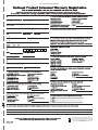
U.S. customer warranty registration.
Page is loading ...
-
 1
1
-
 2
2
-
 3
3
-
 4
4
-
 5
5
-
 6
6
-
 7
7
-
 8
8
-
 9
9
-
 10
10
-
 11
11
-
 12
12
-
 13
13
-
 14
14
-
 15
15
-
 16
16
-
 17
17
-
 18
18
-
 19
19
-
 20
20
-
 21
21
-
 22
22
-
 23
23
-
 24
24
-
 25
25
-
 26
26
-
 27
27
-
 28
28
-
 29
29
-
 30
30
-
 31
31
-
 32
32
-
 33
33
-
 34
34
-
 35
35
-
 36
36
-
 37
37
-
 38
38
-
 39
39
-
 40
40
-
 41
41
-
 42
42
-
 43
43
-
 44
44
-
 45
45
-
 46
46
-
 47
47
-
 48
48
-
 49
49
-
 50
50
-
 51
51
-
 52
52
-
 53
53
-
 54
54
-
 55
55
-
 56
56
-
 57
57
-
 58
58
-
 59
59
-
 60
60
-
 61
61
-
 62
62
-
 63
63
-
 64
64
-
 65
65
-
 66
66
-
 67
67
-
 68
68
-
 69
69
-
 70
70
-
 71
71
-
 72
72
-
 73
73
-
 74
74
-
 75
75
-
 76
76
-
 77
77
-
 78
78
-
 79
79
-
 80
80
-
 81
81
-
 82
82
-
 83
83
-
 84
84
-
 85
85
-
 86
86
-
 87
87
-
 88
88
-
 89
89
-
 90
90
-
 91
91
-
 92
92
-
 93
93
-
 94
94
-
 95
95
-
 96
96
-
 97
97
-
 98
98
-
 99
99
-
 100
100
-
 101
101
-
 102
102
-
 103
103
-
 104
104
-
 105
105
-
 106
106
-
 107
107
-
 108
108
-
 109
109
-
 110
110
-
 111
111
-
 112
112
-
 113
113
-
 114
114
-
 115
115
-
 116
116
-
 117
117
-
 118
118
-
 119
119
-
 120
120
-
 121
121
-
 122
122
-
 123
123
-
 124
124
-
 125
125
-
 126
126
-
 127
127
-
 128
128
-
 129
129
-
 130
130
-
 131
131
-
 132
132
-
 133
133
-
 134
134
-
 135
135
-
 136
136
-
 137
137
-
 138
138
-
 139
139
-
 140
140
-
 141
141
-
 142
142
-
 143
143
-
 144
144
-
 145
145
-
 146
146
-
 147
147
-
 148
148
-
 149
149
-
 150
150
-
 151
151
-
 152
152
-
 153
153
-
 154
154
-
 155
155
-
 156
156


Peavey PVXp 800-Watt 15 inch Powered Subwoofer Owner's manual
- Category
- Supplementary music equipment
- Type
- Owner's manual
Ask a question and I''ll find the answer in the document
Finding information in a document is now easier with AI
in other languages
- italiano: Peavey PVXp 800-Watt 15 inch Powered Subwoofer Manuale del proprietario
- français: Peavey PVXp 800-Watt 15 inch Powered Subwoofer Le manuel du propriétaire
- español: Peavey PVXp 800-Watt 15 inch Powered Subwoofer El manual del propietario
- Deutsch: Peavey PVXp 800-Watt 15 inch Powered Subwoofer Bedienungsanleitung
- português: Peavey PVXp 800-Watt 15 inch Powered Subwoofer Manual do proprietário
- 日本語: Peavey PVXp 800-Watt 15 inch Powered Subwoofer 取扱説明書
- svenska: Peavey PVXp 800-Watt 15 inch Powered Subwoofer Bruksanvisning
- suomi: Peavey PVXp 800-Watt 15 inch Powered Subwoofer Omistajan opas
Related papers
-
Peavey IPR 3000 User manual
-
-
-
-
-
 Peavy 4000 User manual
-
Peavy IPR2 2000 Power Amplifier User manual
-
-
-

Other documents
-
Crest Audio Pro-LITE 7.5 User manual
-
Crest Audio CC 4000 User manual
-
Samsung NP930X5JI User manual
-
Samsung NP910S5JI User manual
-
Work-pro ARC SUB 12 User manual
-
-
-
Crest Audio Pro-LITE 2.0 DSP User manual
-
Crest Audio CLh 6000C User manual
-
Shure X2u User guide