Page is loading ...

For more information on other great Peavey products, visit your local Peavey dealer or go online to www.peavey.com
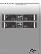
Power Amplifier Owner's Manual
CS
®
3
000/
4
000/
4
080
HZ

ENGLISH
IMPORTANT SAFETY INSTRUCTIONS
WARNING: When using electrical products, basic cautions should always be followed, including the following:
1. Read these instructions.
2. Keep these instructions.
3. Heed all warnings.
4. Follow all instructions.
5. Do not use this apparatus near water.
6. Clean only with a dry cloth.
7. Do not block any of the ventilation openings. Install in accordance with manufacturer’s instructions.
8. Do not install near any heat sources such as radiators, heat registers, stoves or other apparatus (including amplifiers) that
produce heat.
9. Do not defeat the safety purpose of the polarized or grounding-type plug. A polarized plug has two blades with one wider than
the other. A grounding type plug has two blades and a third grounding plug. The wide blade or third prong is provided for your
safety. If the provided plug does not fit into your outlet, consult an electrician for replacement of the obsolete outlet.
10. Protect the power cord from being walked on or pinched, particularly at plugs, convenience receptacles, and the point they exit
from the apparatus.
11. Only use attachments/accessories provided by the manufacturer.
12. Use only with a cart, stand, tripod, bracket, or table specified by the manufacturer, or sold with the apparatus. When a cart is
used, use caution when moving the cart/apparatus combination to avoid injury from tip-over.
13. Unplug this apparatus during lightning storms or when unused for long periods of time.
14. Refer all servicing to qualified service personnel. Servicing is required when the apparatus has been damaged in any way, such
as power-supply cord or plug is damaged, liquid has been spilled or objects have fallen into the apparatus, the apparatus has
been exposed to rain or moisture, does not operate normally, or has been dropped.
15. Never break off the ground pin. Write for our free booklet “Shock Hazard and Grounding.” Connect only to a power supply of the
type marked on the unit adjacent to the power supply cord.
16. If this product is to be mounted in an equipment rack, rear support should be provided.
17. Note for UK only: If the colors of the wires in the mains lead of this unit do not correspond with the terminals in your plug‚
proceed as follows: a) The wire that is colored green and yellow must be connected to the terminal that is marked by the letter
E‚ the earth symbol‚ colored green or colored green and yellow. b) The wire that is colored blue must be connected to the
terminal that is marked with the letter N or the color black. c) The wire that is colored brown must be connected to the terminal
that is marked with the letter L or the color red.
18. This electrical apparatus should not be exposed to dripping or splashing and care should be taken not to place objects
containing liquids, such as vases, upon the apparatus.
19. The on/off switch in this unit does not break both sides of the primary mains. Hazardous energy can be present inside the
chassis when the on/off switch is in the off position. The mains plug or appliance coupler is used as the disconnect device, the
disconnect device shall remain readily operable.
20. Exposure to extremely high noise levels may cause a permanent hearing loss. Individuals vary considerably in susceptibility to
noise-induced hearing loss, but nearly everyone will lose some hearing if exposed to sufficiently intense noise for a sufficient
time. The U.S. Government’s Occupational Safety and Health Administration (OSHA) has specified the following permissible
noise level exposures:
Duration Per Day In Hours Sound Level dBA, Slow Response
8 90
6 92
4 95
3 97
2 100
11⁄2 102
1 105
1⁄2 110
1⁄4orless 115
According to OSHA, any exposure in excess of the above permissible limits could result in some hearing loss. Earplugs or protectors to
the ear canals or over the ears must be worn when operating this amplification system in order to prevent a permanent hearing loss, if
exposure is in excess of the limits as set forth above. To ensure against potentially dangerous exposure to high sound pressure levels, it is
recommended that all persons exposed to equipment capable of producing high sound pressure levels such as this amplification system be
protected by hearing protectors while this unit is in operation.
SAVE THESE INSTRUCTIONS!

人体への電気ショックの危険が考えられる製品筐体内の非絶縁「危険電圧」の存在をユーザーに警告す るものです。
製品に付属している説明書に記載の重要な操作およびメンテナンス(サービス)要領の存在をユーザーに警告するものです。
注意: 電気ショックの危険あり — 開けないでください!
注意: 電気ショックの危険を低減するため、カバーを外さないでください。内部部品はユーザーによるサービス不可。資格のあるサー
ビス要因のサービスを要請してください。
警告:電気ショックまたは火災の危険を避けるため、この装置を雨または湿気にさらしてはなりません。ま た、過敏など液体を含む物を
この装置上に置いてはなりません。この装置を使用する前に、警告事項につ いて操作ガイドをお読みください。
Intended to alert the user to the presence of uninsulated “dangerous voltage” within the product’s enclosure that may be of sufcient
magnitude to constitute a risk of electric shock to persons.
Intended to alert the user of the presence of important operating and maintenance (servicing) instructions in the literature accompanying
the product.
CAUTION: Risk of electrical shock — DO NOT OPEN!
CAUTION: To reduce the risk of electric shock, do not remove cover. No user serviceable parts inside. Refer servicing to qualied service
personnel.
WARNING: To prevent electrical shock or re hazard, this apparatus should not be exposed to rain or moisture‚ and objects lled with
liquids‚ such as vases‚ should not be placed on this apparatus. Before using this apparatus‚ read the operating guide for further warnings.
JAPANESE
SPANISHENGLISH FRENCH
DEUTSCH
Ce symbole est utilisé dans ce manuel pour indiquer à l’utilisateur la présence d’une tension dangereuse pouvant être d’amplitude
sufsante pour constituer un risque de choc électrique.
Ce symbole est utilisé dans ce manuel pour indiquer à l’utilisateur qu’il ou qu’elle trouvera d’importantes instructions concernant l’utilisation
et l’entretien de l’appareil dans le paragraphe signalé.
ATTENTION: Risques de choc électrique — NE PAS OUVRIR!
ATTENTION: An de réduire le risque de choc électrique, ne pas enlever le couvercle. Il ne se trouve à l’intérieur aucune pièce pouvant
être reparée par l’utilisateur. Conez I’entretien et la réparation de l’appareil à un réparateur Peavey agréé.
AVIS: Dans le but de reduire les risques d’incendie ou de decharge electrique, cet appareil ne doit pas etre expose a la pluie ou a l’humidite
et aucun objet rempli de liquide, tel qu’un vase, ne doit etre pose sur celui-ci. Avant d’utiliser de cet appareil, lisez attentivement le guide
fonctionnant pour avertissements supplémentaires.
Dieses Symbol soll den Anwender vor unisolierten gefährlichen Spannungen innerhalb des Gehäuses warnen, die von Ausreichender
Stärke sind, um einen elektrischen Schlag verursachen zu können.
Dieses Symbol soll den Benutzer auf wichtige Instruktionen in der Bedienungsanleitung aufmerksam machen, die Handhabung und
Wartung des Produkts betreffen.
VORSICHT: Risiko — Elektrischer Schlag! Nicht öffnen!
VORSICHT: Um das Risiko eines elektrischen Schlages zu vermeiden, nicht die Abdeckung enfernen. Es benden sich keine Teile darin,
die vom Anwender repariert werden könnten. Reparaturen nur von qualiziertem Fachpersonal durchführen lassen.
WARNUNG: Um elektrischen Schlag oder Brandgefahr zu verhindern, sollte dieser Apparat nicht Regen oder Feuchtigkeit ausgesetzt
werden und Gegenstände mit Flüssigkeiten gefuellt, wie Vasen, nicht auf diesen Apparat gesetzt werden. Bevor dieser Apparat verwendet
wird, lesen Sie bitte den Funktionsführer für weitere Warnungen.
Este símbolo tiene el propósito, de alertar al usuario de la presencia de “(voltaje) peligroso” sin aislamiento dentro de la caja del producto
y que puede tener una magnitud suciente como para constituir riesgo de descarga eléctrica.
Este símbolo tiene el propósito de alertar al usario de la presencia de instruccones importantes sobre la operación y mantenimiento en la
información que viene con el producto.
PRECAUCION: Riesgo de descarga eléctrica ¡NO ABRIR!
PRECAUCION: Para disminuír el riesgo de descarga eléctrica, no abra la cubierta. No hay piezas útiles dentro. Deje todo mantenimiento
en manos del personal técnico cualicado.
ADVERTENCIA: Para prevenir choque electrico o riesgo de incendios, este aparato no se debe exponer a la lluvia o a la humedad. Los
objetos llenos de liquidos, como los oreros, no se deben colocar encima de este aparato. Antes de usar este aparato, lea la guia de
funcionamiento para otras advertencias.

CS
®
3
000/
4
000/
4
080
HZ
Power Amplifiers
Congratulations on your purchase of a Peavey CS Series power amplifier! Designed for years of reliable operation, CS Series
amplifiers offer the sonic superiority and unsurpassed reliability for which Peavey is famous in a rugged, compact unit.
Advanced technologies and extensive protection circuitry allow operation with greater efficiency, even under difficult loads
and power conditions. The DDT
™
(Distortion Detection Technique) circuit ensures trouble-free operation into loads as low
as 2 ohms (4 ohms for model CS
4
080 HZ), protects speakers and ensures, protects drivers and ensures sonic integrity even
in extreme overload conditions. Peavey’s high-efficiency design uses tunnel-cooled heat sinks and dual-speed DC fans for
consistent lower overall operating temperature, resulting in longer output transistor life.
Peavey CS Series amplifiers are simple to operate and housed in ultra-strong steel chassis, but improper use can be
dangerous. Some CS Series amplifiers are very high powered and can put out high voltages and sizable currents at frequencies
up to 30 kHz. Always use safe operating techniques with these amplifiers.
FOR YOUR SAFETY, READ THE IMPORTANT PRECAUTIONS SECTION, AS WELL AS INPUT, OUTPUT AND POWER
CONNECTION SECTIONS.
Unpacking
Upon
unpacking, inspect the amplifier. If you find any damage, notify your supplier immediately. Only the consignee
(the supplier from whom you purchased the amplifier) may institute a claim with the carrier for damage incurred
during shipping. Be sure to save the carton and all packing materials. Should you ever need to ship the unit back to
Peavey or one of its offices, service centers or the supplier, use only the original factory packing. If the shipping carton
is unavailable, contact Peavey to obtain a replacement.
Mounting
CS Series amplifiers will mount in standard 19" racks. Rear mounting ears are also provided for additional support,
which is recommended in non-permanent installations like mobile or touring sound systems. Because of the cables
and connectors on the rear panel, a right angle or offset screwdriver or hex key will make it easier to fasten the rear
mounting ears to the rails.
Cooling Requirements
CS Series amplifiers use a forced-air cooling system to maintain a low, consistent operating temperature. Air is
drawn into the amplifier by fans on the back panel and courses through the cooling fins of the tunnel-configured
channel heat sinks, then exhausts through the front panel grilles. If either heat sink gets too hot, a sensing circuit will
disconnect the load for that particular channel. It is important to have an air inlet at the back of the amplifier to allow
cooling air to enter. If the amp is rack mounted, do not use doors or covers on the back of the rack, as the intake air
must flow without resistance. Make sure that there is one (1) standard rack space opening for every three mounted
power amplifiers.
ENGLISH

0QFSBUJOH1SFDBVUJPOT
.BLFTVSFUIFNBJOTWPMUBHFJTDPSSFDUBOEJTUIFTBNFBTUIBUQSJOUFEPOUIFSFBSPGUIFBNQMJGJFS%BNBHFDBVTFECZ
DPOOFDUJOHUIFBNQMJGJFSUPJNQSPQFS"$WPMUBHFJTOPUDPWFSFECZBOZ$4
4FSJFTXBSSBOUZ4FFUIF$POOFDUJOH1PXFS
TFDUJPOGPSNPSFJOGPSNBUJPOPOWPMUBHFSFRVJSFNFOUT
/PUF"MXBZTUVSOPGGBOEEJTDPOOFDUUIFBNQMJGJFSGSPNNBJOTWPMUBHFCFGPSFNBLJOHBVEJPDPOOFDUJPOT"MTPBTBO
FYUSBQSFDBVUJPOIBWFUIFBUUFOVBUPSTUVSOFEEPXOEVSJOHQPXFSVQ
"MUIPVHIUIF$4);BNQMJGJFSTIBWF3BNQ6Q
DJSDVJUSZXIJDISBJTFTUIFTJHOBMMFWFMHSBEVBMMZBGUFS
UIFPVUQVUSFMBZDMPTFTJUJTBMXBZTBHPPEJEFBUPIBWFUIFHBJODPOUSPMTUVSOFEEPXOEVSJOHQPXFSVQUPQSFWFOU
TQFBLFSEBNBHFJGUIFSFJTBIJHITJHOBMMFWFMBUUIFJOQVUT"MXBZTVTFIJHIRVBMJUZJOQVUBOETQFBLFSDBCMFTUP
FOTVSFUSPVCMFGSFFPQFSBUJPO.PTUJOUFSNJUUFOUQSPCMFNTBSFDBVTFECZGBVMUZDBCMFT
$POTVMUUIF8JSF(BVHF$IBSUTQBHFUPEFUFSNJOFQSPQFSHBVHFTGPSEJGGFSJOHMPBEJNQFEBODFTBOEDBCMFMFOHUIT
$BCMFSFTJTUBODFSPCTBNQMJGJFSQPXFSJOUXPXBZTQPXFSMPTUEJSFDUMZUPSFTJTUBODF*
3MPTTBOECZJODSFBTJOHUIF
JNQFEBODFPGUIFMPBEQSFTFOUFEUPUIFBNQMJGJFSUIFSFCZEFDSFBTJOHUIFQPXFSEFNBOEFEPGUIFBNQMJGJFS"MTPNBLF
TVSFUIFNPEFTXJUDIJTDPSSFDUMZTFUGPSUIFEFTJSFEBQQMJDBUJPO4FFTFDUJPOTPO4UFSFP1BSBMMFMBOE#SJEHFE.POP
0QFSBUJPOGPSNPSFJOGPSNBUJPO
$POOFDUJOH*OQVUT
*OQVUDPOOFDUJPOTBSFNBEFWJBUIFUISFFQJO9-3QJOPSNNQMVH²DPNCJ³DPOOFDUPSTPOUIFSFBSQBOFMPGUIF
BNQMJGJFS5IFJOQVUTBSFBDUJWFMZCBMBODFEBOEUIFPWFSMPBEQPJOUJTIJHIFOPVHIUPBDDFQUUIFNBYJNVNPVUQVUMFWFM
PGWJSUVBMMZBOZTJHOBMTPVSDF
$POOFDUJOH0VUQVUT
"MMNPEFMTIBWFUXPPVUQVUTQFBLFSDPOOFDUJPOTQFSDIBOOFM$BCMFTDBOCFDPOOFDUFEXJUICBOBOBQMVHTTQBEF
MVHTPSCBSFXJSFUPUIFGJWFXBZCJOEJOHQPTUT5IFQSFGFSSFEDPOOFDUJPONFUIPEJTWJBUIF4QFBLPO
DPOOFDUPST1JO
DPOOFDUJPOTBSFOPUFEPOUIFSFBSQBOFM
$POOFDUJOH1PXFS
$44FSJFTBNQMJGJFSQPXFSSFRVJSFNFOUTBSFSBUFEBUQPXFSUZQJDBMNVTJDDPOEJUJPOTBOEQPXFSFYUSFNF
NVTJDDPOEJUJPOT5IFNBYJNVNQPXFSDVSSFOUESBXSBUJOHJTMJNJUFEPOMZCZUIFGSPOUQBOFMDJSDVJUCSFBLFS$POTVMU
UIFTQFDJGJDBUJPOTJOUIF"QQFOEJDFTTFDUJPOGPSGJHVSFTPOUIFDVSSFOUUIBUFBDIBNQMJGJFSXJMMEFNBOE6OMFTT
PUIFSXJTFTQFDJGJFEXIFOPSEFSFE1FBWFZBNQMJGJFSTTIJQQFEUPDVTUPNFSTBSFDPOGJHVSFEBTGPMMPXT
/PSUI"NFSJDB 7"$)[
&VSPQF"TJB"VTUSBMJB 7"$)[
4PVUI"NFSJDB 7"$)[PS7"$)[
/PUF"MXBZTUVSOPGGBOEEJTDPOOFDUUIFBNQMJGJFSGSPNNBJOTWPMUBHFCFGPSFNBLJOHBVEJPDPOOFDUJPOT"TBOFYUSB
QSFDBVUJPOIBWFUIFBUUFOVBUPSTUVSOFEEPXOXIJMFQPXFSJOHVQ
*OUSPEVDUJPO
CAUTION: This amplier is capable of producing hazardous voltage at the speaker outputs under certain
operation conditions. The speaker outputs must be protected from direct contact and caution must be observed
to lessen the accidental contact with hazardous energy on speaker connections, terminals, and speaker wiring.
0QFSBUJOH1SFDBVUJPOT
.BLFTVSFUIFNBJOTWPMUBHFJTDPSSFDUBOEJTUIFTBNFBTUIBUQSJOUFEPOUIFSFBSPGUIFBNQMJGJFS%BNBHFDBVTFECZ
DPOOFDUJOHUIFBNQMJGJFSUPJNQSPQFS"$WPMUBHFJTOPUDPWFSFECZBOZ$4
4FSJFTXBSSBOUZ4FFUIF$POOFDUJOH1PXFS
TFDUJPOGPSNPSFJOGPSNBUJPOPOWPMUBHFSFRVJSFNFOUT
/PUF"MXBZTUVSOPGGBOEEJTDPOOFDUUIFBNQMJGJFSGSPNNBJOTWPMUBHFCFGPSFNBLJOHBVEJPDPOOFDUJPOT"MTPBTBO
FYUSBQSFDBVUJPOIBWFUIFBUUFOVBUPSTUVSOFEEPXOEVSJOHQPXFSVQ
"MUIPVHIUIF$4);BNQMJGJFSTIBWF3BNQ6Q
DJSDVJUSZXIJDISBJTFTUIFTJHOBMMFWFMHSBEVBMMZBGUFS
UIFPVUQVUSFMBZDMPTFTJUJTBMXBZTBHPPEJEFBUPIBWFUIFHBJODPOUSPMTUVSOFEEPXOEVSJOHQPXFSVQUPQSFWFOU
TQFBLFSEBNBHFJGUIFSFJTBIJHITJHOBMMFWFMBUUIFJOQVUT"MXBZTVTFIJHIRVBMJUZJOQVUBOETQFBLFSDBCMFTUP
FOTVSFUSPVCMFGSFFPQFSBUJPO.PTUJOUFSNJUUFOUQSPCMFNTBSFDBVTFECZGBVMUZDBCMFT
$POTVMUUIF8JSF(BVHF$IBSUTQBHFUPEFUFSNJOFQSPQFSHBVHFTGPSEJGGFSJOHMPBEJNQFEBODFTBOEDBCMFMFOHUIT
$BCMFSFTJTUBODFSPCTBNQMJGJFSQPXFSJOUXPXBZTQPXFSMPTUEJSFDUMZUPSFTJTUBODF*
3MPTTBOECZJODSFBTJOHUIF
JNQFEBODFPGUIFMPBEQSFTFOUFEUPUIFBNQMJGJFSUIFSFCZEFDSFBTJOHUIFQPXFSEFNBOEFEPGUIFBNQMJGJFS"MTPNBLF
TVSFUIFNPEFTXJUDIJTDPSSFDUMZTFUGPSUIFEFTJSFEBQQMJDBUJPO4FFTFDUJPOTPO4UFSFP1BSBMMFMBOE#SJEHFE.POP
0QFSBUJPOGPSNPSFJOGPSNBUJPO
$POOFDUJOH*OQVUT
*OQVUDPOOFDUJPOTBSFNBEFWJBUIFUISFFQJO9-3QJOPSNNQMVH²DPNCJ³DPOOFDUPSTPOUIFSFBSQBOFMPGUIF
BNQMJGJFS5IFJOQVUTBSFBDUJWFMZCBMBODFEBOEUIFPWFSMPBEQPJOUJTIJHIFOPVHIUPBDDFQUUIFNBYJNVNPVUQVUMFWFM
PGWJSUVBMMZBOZTJHOBMTPVSDF
$POOFDUJOH0VUQVUT
"MMNPEFMTIBWFUXPPVUQVUTQFBLFSDPOOFDUJPOTQFSDIBOOFM$BCMFTDBOCFDPOOFDUFEXJUICBOBOBQMVHTTQBEF
MVHTPSCBSFXJSFUPUIFGJWFXBZCJOEJOHQPTUT5IFQSFGFSSFEDPOOFDUJPONFUIPEJTWJBUIF4QFBLPO
DPOOFDUPST1JO
DPOOFDUJPOTBSFOPUFEPOUIFSFBSQBOFM
$POOFDUJOH1PXFS
$44FSJFTBNQMJGJFSQPXFSSFRVJSFNFOUTBSFSBUFEBUQPXFSUZQJDBMNVTJDDPOEJUJPOTBOEQPXFSFYUSFNF
NVTJDDPOEJUJPOT5IFNBYJNVNQPXFSDVSSFOUESBXSBUJOHJTMJNJUFEPOMZCZUIFGSPOUQBOFMDJSDVJUCSFBLFS$POTVMU
UIFTQFDJGJDBUJPOTJOUIF"QQFOEJDFTTFDUJPOGPSGJHVSFTPOUIFDVSSFOUUIBUFBDIBNQMJGJFSXJMMEFNBOE6OMFTT
PUIFSXJTFTQFDJGJFEXIFOPSEFSFE1FBWFZBNQMJGJFSTTIJQQFEUPDVTUPNFSTBSFDPOGJHVSFEBTGPMMPXT
/PSUI"NFSJDB 7"$)[
&VSPQF"TJB"VTUSBMJB 7"$)[
4PVUI"NFSJDB 7"$)[PS7"$)[
/PUF"MXBZTUVSOPGGBOEEJTDPOOFDUUIFBNQMJGJFSGSPNNBJOTWPMUBHFCFGPSFNBLJOHBVEJPDPOOFDUJPOT"TBOFYUSB
QSFDBVUJPOIBWFUIFBUUFOVBUPSTUVSOFEEPXOXIJMFQPXFSJOHVQ
*OUSPEVDUJPO

Wire Guage Charts
Stranded Cable Lgth.
(m)
2
5
10
30
Wire Gauge (mm
2
)
0.3
0.5
0.75
1.5
2.5
4
0.5
0.75
1.5
2.5
4
6
0.5
0.75
1.5
2.5
4
6
0.75
1.5
2.5
4
6
10
Power Loss
(8 ohm load)
2.9%
1.74
1.16
0.58
0.35
0.22
4.3%
2.9
1.45
0.87
0.55
0.37
8.24%
5.6
2.9
1.74
1.09
0.73
15.5%
8.2
5.1
3.2
2.2
1.31
Power Loss
(4 ohm load)
5.6%
3.4
2.3
1.16
0.70
0.44
8.2%
5.6
2.9
1.74
1.09
0.73
15.5%
10.8
5.6
2.9
1.74
1.09
25%
15.5
9.8
6.3
4.3
2.6
Power Loss
(2 ohm load)
10.8%
6.7
4.5
2.3
1.39
0.87
15.5%
10.8
5.6
3.4
2.2
1.45
28%
19.9
10.8
6.7
4.3
2.9
45%
28
18.2
12.0
8.2
5.1
Stranded Cable Lgth.
(ft.)
5
10
40
80
Wire Gauge (AWG)
18
16
14
12
10
18
16
14
12
10
18
16
14
12
10
8
18
16
14
12
10
8
Power Loss
(8 ohm load)
0.81%
0.51
0.32
0.20
0.128
1.61%
1.02
0.64
0.40
0.25
6.2%
4.0
2.5
1.60
1.01
0.60
11.9%
7.7
5.0
3.2
2.0
1.20
Power Loss
(4 ohm load)
1.61%
1.02
0.64
0.40
0.25
3.2%
2.0
1.28
0.80
0.51
11.9%
7.7
5.0
3.2
2.0
1.20
22%
14.6
9.6
6.2
4.0
2.4
Power Loss
(2 ohm load)
3.2%
2.0
1.28
0.80
0.51
6.2%
4.0
2.5
1.60
1.01
22%
14.6
9.6
6.2
4.0
2.4
37%
26
17.8
11.8
7.7
4.7

Stereo Operation
For stereo (dual channel) operation, turn the amplifier OFF and set the mode select switches on the back panel to the
out (extended) position. In this mode, both channels operate independently of each other, with their input attenuators
controlling their respective levels. Thus, a signal at channel A’s input produces an amplified signal at channel A’s
output, while a signal at channel B’s input produces an amplified signal at channel B’s output.
Parallel Operation
For parallel (dual-channel/single input) operation, turn the amplifier OFF and set the connector mode (CONN MODE)
switch to the parallel position by depressing the switch. Both input connectors are then strapped together and drive
both channels with the same input signal. Because both connectors are strapped together, either connector can be
used with a patch cable to drive the input of another amplifier. Output connections are the same as in Stereo mode.
Both input attenuators remain active when in Parallel mode, allowing you to set different levels for each channel.
Power and other general performance specifications are the same as in Stereo mode.
Bridged Mono Operation
Both amplifier channels can be bridged together to make a very powerful single-channel monaural amplifier. Use
extreme caution when operating in the bridged mode; potentially lethal voltage may be present at the output
terminals. To bridge the amplifier, depress the rear panel Bridge switch to the IN position. Direct the signal to channel
A’s input and connect the speakers across the hot outputs (the “+” binding posts) of channels A and B. Only channel
A’s input attenuator is active while in Bridge Mono mode. Both connectors are strapped together, so either connector
can be used with a patch cable to drive the input of another amplifier.
Unlike the stereo mode, in which one side of each output is at ground, both sides are hot in bridged mode. Channel A’s
side is the same polarity as its input with the minimum nominal load impedance being 4 ohms (equivalent to driving
both channels at 2 ohms) in bridged mode. Driving bridged loads of less than 4 ohms will activate the DDT
™
circuitry
(see Indicators section), resulting in a loss of power, and may also cause a thermal (overheating) overload.
Operation Modes

11
'SPOU1BOFM
"$1PXFS4XJUDI$JSDVJU#SFBLFS
5IF$4
4FSJFTBNQMJGJFSTGFBUVSFBDPNCJOBUJPO"$TXJUDIDJSDVJUCSFBLFSPOUIFGSPOUQBOFM*GUIFTXJUDITIVUTPGG
EVSJOHOPSNBMVTFQVTIJUCBDLUPUIF0/QPTJUJPOPODF*GUIFTXJUDIXJMMOPUTUBZJOUIF0/QPTJUJPOUIFBNQMJGJFS
OFFETTFSWJDJOH
*OQVU"UUFOVBUPST
8IFOFWFSQPTTJCMFTFUUIFBUUFOVBUPSTGVMMZDMPDLXJTFUPNBJOUBJOPQUJNVNTZTUFNIFBESPPN5IFJOQVUBUUFOVBUPS
DPOUSPMTPOFGPSDIBOOFM"POFGPSDIBOOFM#MPDBUFEPOUIFGSPOUQBOFMBUUFOVBUFTJHOBMMFWFMEFDSFBTFHBJOGPSUIF
SFTQFDUJWFBNQMJGJFSDIBOOFMTJOBMMNPEFT4FFUIFTQFDJGJDBUJPOTBUUIFFOEPGUIJTNBOVBMGPSTUBOEBSEWPMUBHFHBJO
BOEJOQVUTFOTJUJWJUZJOGPSNBUJPO
$0//.0%&4FMFDU4XJUDI
%FQSFTTJOHUIFSFBSQBOFM$0//.0%&TFMFDUTXJUDIDPOOFDUTCPUIJOQVUDPOOFDUPSTUPHFUIFSJOQBSBMMFM5IJTEJSFDUT
UIFTBNFJOQVUTJHOBMUPCPUIDIBOOFMTBOEBMMPXTPOFDPOOFDUPSUPCFVTFEXJUIBQBUDIDBCMFUPESJWFBOPUIFS
BNQMJGJFS8IFOJOUIFPVUQPTJUJPOCPUIJOQVUDPOOFDUPSTPQFSBUFJOEFQFOEFOUMZ%POPUPQFSBUFUIF$0//.0%&
TFMFDUTXJUDIXJUIUIFBNQMJGJFSQPXFSFEPO4FFUIFTFDUJPOTPO4UFSFP1BSBMMFMBOE#SJEHFE.POPNPEFGPSNPSF
JOGPSNBUJPO
".1.0%&4FMFDU4XJUDI
5IFSFBSQBOFM".1.0%&TFMFDUTXJUDIEFUFSNJOFTJGUIFBNQMJGJFSJTJO4UFSFPUXPDIBOOFMTPSJO#SJEHFE.POP
NPEF%POPUPQFSBUFUIF".1.0%&TFMFDUTXJUDIXJUIUIFBNQMJGJFSQPXFSFEPO4FFUIF0QFSBUJPOT.PEFTFDUJPO
GPSNPSFJOGPSNBUJPOPO4UFSFP1BSBMMFMBOE#SJEHFE.POPNPEFBQQMJDBUJPOT
4XJUDIFT$POUSPMT
3FBS1BOFM
CAUTION: The on/off switch in this unit does not break both sides of the primary mains.
Hazardous energy can be present inside the chassis when the on/off switch is in the off position.
'SPOU1BOFM
"$1PXFS4XJUDI$JSDVJU#SFBLFS
5IF$4
4FSJFTBNQMJGJFSTGFBUVSFBDPNCJOBUJPO"$TXJUDIDJSDVJUCSFBLFSPOUIFGSPOUQBOFM*GUIFTXJUDITIVUTPGG
EVSJOHOPSNBMVTFQVTIJUCBDLUPUIF0/QPTJUJPOPODF*GUIFTXJUDIXJMMOPUTUBZJOUIF0/QPTJUJPOUIFBNQMJGJFS
OFFETTFSWJDJOH
*OQVU"UUFOVBUPST
8IFOFWFSQPTTJCMFTFUUIFBUUFOVBUPSTGVMMZDMPDLXJTFUPNBJOUBJOPQUJNVNTZTUFNIFBESPPN5IFJOQVUBUUFOVBUPS
DPOUSPMTPOFGPSDIBOOFM"POFGPSDIBOOFM#MPDBUFEPOUIFGSPOUQBOFMBUUFOVBUFTJHOBMMFWFMEFDSFBTFHBJOGPSUIF
SFTQFDUJWFBNQMJGJFSDIBOOFMTJOBMMNPEFT4FFUIFTQFDJGJDBUJPOTBUUIFFOEPGUIJTNBOVBMGPSTUBOEBSEWPMUBHFHBJO
BOEJOQVUTFOTJUJWJUZJOGPSNBUJPO
$0//.0%&4FMFDU4XJUDI
%FQSFTTJOHUIFSFBSQBOFM$0//.0%&TFMFDUTXJUDIDPOOFDUTCPUIJOQVUDPOOFDUPSTUPHFUIFSJOQBSBMMFM5IJTEJSFDUT
UIFTBNFJOQVUTJHOBMUPCPUIDIBOOFMTBOEBMMPXTPOFDPOOFDUPSUPCFVTFEXJUIBQBUDIDBCMFUPESJWFBOPUIFS
BNQMJGJFS8IFOJOUIFPVUQPTJUJPOCPUIJOQVUDPOOFDUPSTPQFSBUFJOEFQFOEFOUMZ%POPUPQFSBUFUIF$0//.0%&
TFMFDUTXJUDIXJUIUIFBNQMJGJFSQPXFSFEPO4FFUIFTFDUJPOTPO4UFSFP1BSBMMFMBOE#SJEHFE.POPNPEFGPSNPSF
JOGPSNBUJPO
".1.0%&4FMFDU4XJUDI
5IFSFBSQBOFM".1.0%&TFMFDUTXJUDIEFUFSNJOFTJGUIFBNQMJGJFSJTJO4UFSFPUXPDIBOOFMTPSJO#SJEHFE.POP
NPEF%POPUPQFSBUFUIF".1.0%&TFMFDUTXJUDIXJUIUIFBNQMJGJFSQPXFSFEPO4FFUIF0QFSBUJPOT.PEFTFDUJPO
GPSNPSFJOGPSNBUJPOPO4UFSFP1BSBMMFMBOE#SJEHFE.POPNPEFBQQMJDBUJPOT
4XJUDIFT$POUSPMT
3FBS1BOFM

CS
®
Series amplifiers feature three front panel LED indicators per channel: PWR (power), SIG (signal) and DDT
™
(Distortion
Detection Technique). These LED indicators inform the user of each channel’s operating status and warn of possible abnormal
conditions.
PWR LED (1)
The Power LED indicates that the channel is operational. It illuminates under normal operation and remains on even
when the channel’s DDT circuit is activated.
SIG LED (2)
The Signal LED illuminates when its channel produces an output signal of greater than 1 volt RMS or 25 mV input
with a 0 dB attenuation of the front panel knobs. This is useful in determining whether a signal is reaching and being
amplified by the amplifier. If the Signal LED is illuminated but no sound is present, that means a signal is present at
the amplifier but a problem may exist after the amplifier, such as in the cables or speakers.
DDT LED (3)
A channel’s DDT LED will illuminate at the onset of clipping. If the LEDs are flashing quickly and intermittently, the
channel is just at the clip threshold, while a steady, bright glow means the amp is clip limiting, or reducing gain to
prevent severely clipped waveforms from reaching the speakers. See Distortion Detection Technique Limiting under
the Protection Features section for more information.
Indicators
Front Panel
1
1
2
2
3
3

The Peavey CS
®
Series incorporates several circuits to protect the amplifier and speakers under virtually any situation. Peavey
has made the amplifiers as foolproof as possible by making them immune to short and open circuits, mismatched loads,
DC voltage and overheating. If a channel goes into the DDT
™
gain reduction mode, the DDT LED illuminates. The clipping
percentage or output power is instantly reduced. When a problem occurs that causes a channel to go into a protection mode,
the PWR (Power) LED for that channel will turn off. DC voltage on the output or excessive subsonic frequencies will cause the
speaker protection relay for that channel to open, protecting the speakers. If an amplifier channel overheats, the relay for that
channel will open, disconnecting the load until the channel cools down, thus protecting the amplifier.
Distortion Detection Technique Limiting
Any time a channel is driven into hard, continuous clipping, the DDT circuit will automatically reduce the channel gain
to a level just slightly into clipping, guarding the speakers against the damaging, high-power, continuous square
waves that may be produced. Situations that may activate the DDT circuit include uncontrolled feedback, oscillations,
an improper equipment setting or malfunction upstream from the amplifier. Normal program transients will not trigger
DDT; only steady, excessive clipping will cause the DDT LED to illuminate.
LFC Impedance Sensing
CS Series amplifiers feature innovative circuitry for safe operation into any load. When an amplifier senses a load
that overstresses the output stage, the Load Fault Correction circuit adjusts the channel gain to a safe level. Extreme
load fault under high power levels will cause the speaker relay to disconnect the load for the associated channel.
This method of output stage protection is far more effective than the standard limiting found on conventional power
amplifiers. The LFC circuit is sonically transparent in normal use and unobtrusive when activated.
Thermal Protection
The internal fans will keep the amplifier operating well within its intended temperature range under all normal
conditions. If a channel’s heat sink temperature reaches 85°C (which may indicate an obstructed air supply), that
channel will independently protect itself by opening the speaker relay to disconnect the load until it has cooled.
During this time, the PWR LED will go out and the cooling fans will continue operating at high speed.
Short Circuit
If an output is shorted, the LFC and thermal circuits will automatically protect the amplifier. The LFC circuit senses
the short circuit as an extremely stressful load condition and attenuates the signal, protecting the channel’s output
transistors from over-current stress. If the short circuit remains, the channel may eventually thermally protect itself by
opening the speaker relay thereby disconnecting the load.
DC Voltage Protection
If an amplifier channel detects DC voltage or subsonic frequencies at its output terminals, the speaker protection relay
for that channel will open, protecting the speakers.
Turn-On/Turn-Off Protection
Upon powering up, the amplifier mutes the input signals and stays in Protect mode with the speaker connect relays
open for approximately four seconds. This allows the internal power supplies to charge and the amplifier to stabilize.
After the relays engage, the signals slowly increase from muted to their normal level. Also, when power is removed,
the input signals are muted so that no thumps or pops are heard.
Protection Features

RampUp
™
Signal Control
Whenever a CS
®
Series amplifier powers up or comes out of a protect mode, the RampUp circuit activates. While the
speakers are disconnected, the RampUp circuit fully attenuates the signal and activates the DDT
™
LED. After the
output relay closes, the signal slowly and gradually raises up to its set level. The PWR LED will illuminate and the
DDT LED will turn off when the signal is no longer attenuated. The RampUp Signal Control circuit has some important
advantages over the conventional instant-on circuits:
1. If a signal is present during power-up (or when coming out of protect), the speakers are spared a sudden,
potentially damaging burst of audio power.
2. Because the gain is reduced until after the output relay closes, no arcing occurs at the contacts, thereby
extending their useful life.
All loudspeakers have electrical, thermal and physical limits that must be observed to prevent damage or failure. Excessive
power, low frequencies applied to high frequency drivers, severely clipped waveforms, and DC voltage can all be fatal to cone
and compression drivers. Peavey CS Series amplifiers automatically protect speakers from DC voltages and subsonic signals.
If using an electronic crossover, be extremely careful that the low and mid bands are connected to the correct amplifiers and
drivers and not to those designed for a higher frequency band. An amplifier’s clipping point is its maximum peak output power,
and some of the higher powered Peavey CS Series amplifiers can deliver more power than many speakers can safely handle. Be
sure the peak power capability of the amplifier is not excessive for your speaker system. For more information, see the section
on Protection Features.
Fuses may also be used to limit power to speaker drivers, although as current-limiting rather than voltage-limiting devices, they
are an imperfect solution, and as the weakest links, they only limit once before needing replacement. Some poor-quality fuses
have a significant series resistance that could degrade the amplifier’s damping of the speaker’s motion and may even deterio-
rate the system’s sound quality. If you elect to use fuses, check with the speaker manufacturer to determine the proper current
rating and time lag required.
Do not drive any low frequency speaker enclosure with frequencies lower than its own tuned frequency; the reduced acousti-
cal damping could cause a ported speaker to bottom out even at moderate power. Consult the speaker system specifications to
determine its frequency limits.
Speaker Protection
Protection Features

A CS Series amplifier requires no routine maintenance and should not need internal adjustment during its lifetime. Your CS
Series amplifier is very powerful and can be potentially dangerous to loudspeakers and humans alike. It is your responsibil-
ity to read the Important Precautions section and to make sure that the amplifier is installed, wired and operated properly as
instructed in this manual. Many loudspeakers can be easily damaged or destroyed by overpowering, especially with the high
power available from a bridged amplifier. Read the Speaker Protection section and always be aware of the speaker’s continuous
and peak power capabilities.
In the unlikely event that your amplifier develops a problem, it must be returned to an authorized distributor, service center or
shipped directly to our factory. To obtain service, contact your nearest Peavey Service Center, Distributor, Dealer, or any of the
worldwide Peavey offices. For contact information, reach Peavey Inc. Customer Service directly:
Telephone: 601-483-5365 (USA)
Fax Number: 601-486-1278 (USA)
For technical inquiries only, the Peavey Technical Services department can be faxed at 601-486-1361 (USA)
Because of the complexity of the design and risk of electrical shock, all repairs must be performed only by qualified technical
personnel. If the unit needs to be shipped back to the factory, it must be sent in its original carton. It is the responsibility of the
person shipping the unit to properly package the amplifier. If you need a product shipping carton, please contact Peavey for a
replacement.
Please visit the Peavey website at: http://www.peavey.com.
Amplifier Maintenance and User Responsibility
Service / Warranty Information

CS
®
Series 3000/4000/4080 HZ
Power Amplifiers
SPECIFICATIONS
CS 3000 CS 4000 CS 4080 HZ
Rated Power Bridged
3,050 watts @ 1 kHz at
<0.1% T.H.D. @ 4 ohms
4,000 watts @ 1 kHz at
<0.1% T.H.D. @ 4 ohms
4,080 watts @ 1 kHz at
<0.1% T.H.D. @ 8 ohms
Rated Power 2 x 2 ohms
1,500 watts per channel
@ 1 kHz <0.05% T.H.D.
both channels driven
2,000 watts per channel
@ 1 kHz <0.1% T.H.D.
both channels driven
N/A
Rated Power 2 x 4 ohms
1,025 watts per channel
@ 1 kHz at <0.05%
T.H.D. both channels
driven
1,350 watts per channel
@ 1 kHz at <0.05%
T.H.D. both channels
driven
2,040 watts per channel
@ 1 kHz at <0.05%
T.H.D. both channels
driven
Rated Power 2 x 8 ohms
650 watts per channel @
1 kHz at <0.05% T.H.D.
both channels driven
800 watts per channel @
1 kHz at <0.05% T.H.D.
both channels driven
1,250 watts per channel
@ 1 kHz at <0.05%
T.H.D. both channels
driven
Rated Power 1 x 2 ohms
2,000 watts @ 1 kHz at
<0.1% T.H.D.
2,550 watts @ 1 kHz at
<0.1% T.H.D.
N/A
Rated Power 1 x 4 ohms
1,275 watts @ 1 kHz at
<0.05% T.H.D.
1,600 watts @ 1 kHz at
<0.05% T.H.D.
2,450 watts @ 1 kHz at
<0.05% T.H.D.
Rated Power 1 x 8 ohms
750 watts @ 1 kHz at
<0.05% T.H.D.
900 watts @ 1 kHz at
<0.05% T.H.D.
1,400 watts @ 1 kHz at
<0.05% T.H.D.
Minimum Load Impedance
2 ohms 2 ohms 4 ohms
Maximum RMS Voltage Swing
86 volts 93 volts 115 volts
Frequency Response
10 Hz - 100 kHz; +0,
-1.5 dB at 1 watt
10 Hz - 100 kHz; +0,
-2 dB at 1 watt
10 Hz - 100 kHz; +0,
-0.75 dB at 1 watt
Power Bandwidth
10 Hz - 35 kHz; +0, -3
dB at rated 4 ohms power
10 Hz - 35 kHz; +0, -3
dB at rated 4 ohms power
10 Hz - 35 kHz; +0, -3
dB at rated 4 ohms power
T.H.D. 2 x 2 ohms
<0.2% @ 1,200 watts
per channel from 20 Hz to
20 kHz
<0.2% @ 1,500 watts
per channel from 20 Hz to
20 kHz
N/A
T.H.D. 2 x 4 ohms
<0.1% @ 925 watts per
channel from 20 Hz to 20
kHz
<0.1% @ 1,150 watts
per channel from 20 Hz to
20 kHz
<0.1% @ 1,650 watts
per channel from 20 Hz to
20 kHz
T.H.D. 2 x 8 ohms
<0.1% @ 600 watts per
channel from 20 Hz to 20
kHz
<0.1% @ 750 watts per
channel from 20 Hz to 20
kHz
<0.1% @ 950 watts per
channel from 20 Hz to 20
kHz
Input CMRR
> - 55 dB @ 1 kHz > - 75 dB @ 1 kHz > - 75 dB @ 1 kHz
Voltage Gain
x 40 (32 dB) x 40 (32 dB) x 40 (32 dB)
Crosstalk
> -55 dB @ 1 kHz at
rated power @ 8 ohms
> -70 dB @ 1 kHz at
rated power @ 8 ohms
> -70 dB @ 1 kHz at
rated power @ 8 ohms
Hum and Noise
> -109 dB, “A” weighted
referenced to rated power
@ 8 ohms
> -108 dB, “A” weighted
referenced to rated power
@ 8 ohms
> -108 dB, “A” weighted
referenced to rated power
@ 8 ohms

CS 3000 CS 4000 CS 4080 HZ
Slew Rate
> 15V/us > 15V/us > 15V/us
Damping Factor (8 ohms)
> 500:1 @ 20 Hz - 1
kHz
> 500:1 @ 20 Hz - 1
kHz
> 500:1 @ 20 Hz - 1
kHz
Phase Response
+5 to - 15 degrees from
20 Hz to 20kHz
+5 to - 12 degrees from
20 Hz to 20kHz
+5 to - 12 degrees from
20 Hz to 20kHz
Input Sensitivity
1.6 volts +/- 3% for 1
kHz. 4 ohms rated power,
1.37 volts +/- 3% for 1
kHz. 2 ohms rated power
1.84 volts +/- 3% for 1
kHz. 4 ohms rated power,
1.58 volts +/- 3% for 1
kHz. 2 ohms rated power
2.25 volts +/- 3% for 1
kHz. 4 ohms rated power
Input Impedance
15 k ohms, balanced 15 k ohms, balanced 15 k ohms, balanced
Current Draw @ 1/8 power
1,540 watts @ 2 ohms,
1,000 watts @ 4 ohms,
610 watts @ 8 ohms
1,825 watts @ 2 ohms,
1,185 watts @ 4 ohms,
720 watts @ 8 ohms
1,185 watts @ 4 ohms,
720 watts @ 8 ohms
Current Draw @ 1/3 power
3,650 watts @ 2 ohms,
2,510 watts @ 4 ohms,
1,535 watts @ 8 ohms
4,535 watts @ 2 ohms,
2,975 watts @ 4 ohms,
1,835 watts @ 8 ohms
2,975 watts @ 4 ohms,
1,835 watts @ 8 ohms
Cooling
Two back panel
temperature dependant
variable speed 80 mm DC
fans
Two back panel
temperature dependant
variable speed 80 mm DC
fans
Two back panel
temperature dependant
variable speed 80 mm DC
fans
Controls
2 front panel attenuators,
rear panel Mode switches
2 front panel attenuators,
rear panel Mode switches
2 front panel attenuators,
rear panel Mode switches
Indicator LEDs
2 DDT™ (clip limiting), 2
Signal presence, 2 Active
status
2 DDT™ (clip limiting), 2
Signal presence, 2 Active
status
2 DDT™ (clip limiting), 2
Signal presence, 2 Active
status
Protection
Thermal, DC, turn-on
bursts, subsonic, incorrect
loads
Thermal, DC, turn-on
bursts, subsonic, incorrect
loads
Thermal, DC, turn-on
bursts, subsonic, incorrect
loads
Connectors
Combi XLR & 6.3 mm
phone input, Speakon
®
and Binding Post speaker
output, 15 amp IEC mains
connector
Combi XLR & 6.3 mm
phone input, Speakon
®
and Binding Post speaker
output, 15 amp IEC mains
connector
Combi XLR & 6.3 mm
phone input, Speakon
®
and Binding Post speaker
output, 15 amp IEC mains
connector
Construction
16 ga. steel with cast front
panel and cast handles
14 ga. steel with cast front
panel and cast handles
16 ga. steel with cast front
panel and cast handles
Dimensions
88.9mm x 482.6mm x
376.3mm + 31.8mm
for rear support ears and
connectors (3.5”x19”x
14.81” + 1.25”) + (1.5”)
for handle depth
88.9mm x 482.6mm x
376.3mm + 31.8mm
for rear support ears and
connectors (3.5”x19”x
4.81” + 1.25”) + (1.5”)
for handle depth.
88.9mm x 482.6mm x
376.3mm + 31.8mm
for rear support ears and
connectors (3.5”x19”x
14.81” + 1.25”) + (1.5”)
for handle depth.
Net Weight
18.05 kg (39.8 lbs.) 19.64 kg (43.3 lbs.) 21.45 kg (47.3 lbs.)
Gross Weight
19.23 kg.(42.4 lbs.) 20.8 kg.(45.8 lbs.) 25.4 kg. (56 lbs.)
All power measurements made at 120 VAC, power transformer cold. 4 ohm power is time limited by magnetic circuit breaker.
CS
®
Series SPECIFICATIONS

Kabelstärkentabellen
Stranded Cable Lgth.
(m)
2
5
10
30
Wire Gauge (mm
2
)
0.3
0.5
0.75
1.5
2.5
4
0.5
0.75
1.5
2.5
4
6
0.5
0.75
1.5
2.5
4
6
0.75
1.5
2.5
4
6
10
Power Loss
(8 ohm load)
2.9%
1.74
1.16
0.58
0.35
0.22
4.3%
2.9
1.45
0.87
0.55
0.37
8.24%
5.6
2.9
1.74
1.09
0.73
15.5%
8.2
5.1
3.2
2.2
1.31
Power Loss
(4 ohm load)
5.6%
3.4
2.3
1.16
0.70
0.44
8.2%
5.6
2.9
1.74
1.09
0.73
15.5%
10.8
5.6
2.9
1.74
1.09
25%
15.5
9.8
6.3
4.3
2.6
Power Loss
(2 ohm load)
10.8%
6.7
4.5
2.3
1.39
0.87
15.5%
10.8
5.6
3.4
2.2
1.45
28%
19.9
10.8
6.7
4.3
2.9
45%
28
18.2
12.0
8.2
5.1
Stranded Cable Lgth.
(ft.)
5
10
40
80
Wire Gauge (AWG)
18
16
14
12
10
18
16
14
12
10
18
16
14
12
10
8
18
16
14
12
10
8
Power Loss
(8 ohm load)
0.81%
0.51
0.32
0.20
0.128
1.61%
1.02
0.64
0.40
0.25
6.2%
4.0
2.5
1.60
1.01
0.60
11.9%
7.7
5.0
3.2
2.0
1.20
Power Loss
(4 ohm load)
1.61%
1.02
0.64
0.40
0.25
3.2%
2.0
1.28
0.80
0.51
11.9%
7.7
5.0
3.2
2.0
1.20
22%
14.6
9.6
6.2
4.0
2.4
Power Loss
(2 ohm load)
3.2%
2.0
1.28
0.80
0.51
6.2%
4.0
2.5
1.60
1.01
22%
14.6
9.6
6.2
4.0
2.4
37%
26
17.8
11.8
7.7
4.7

La Charte De Dimensions Des Cables
Stranded Cable Lgth.
(m)
2
5
10
30
Wire Gauge (mm
2
)
0.3
0.5
0.75
1.5
2.5
4
0.5
0.75
1.5
2.5
4
6
0.5
0.75
1.5
2.5
4
6
0.75
1.5
2.5
4
6
10
Power Loss
(8 ohm load)
2.9%
1.74
1.16
0.58
0.35
0.22
4.3%
2.9
1.45
0.87
0.55
0.37
8.24%
5.6
2.9
1.74
1.09
0.73
15.5%
8.2
5.1
3.2
2.2
1.31
Power Loss
(4 ohm load)
5.6%
3.4
2.3
1.16
0.70
0.44
8.2%
5.6
2.9
1.74
1.09
0.73
15.5%
10.8
5.6
2.9
1.74
1.09
25%
15.5
9.8
6.3
4.3
2.6
Power Loss
(2 ohm load)
10.8%
6.7
4.5
2.3
1.39
0.87
15.5%
10.8
5.6
3.4
2.2
1.45
28%
19.9
10.8
6.7
4.3
2.9
45%
28
18.2
12.0
8.2
5.1
Stranded Cable Lgth.
(ft.)
5
10
40
80
Wire Gauge (AWG)
18
16
14
12
10
18
16
14
12
10
18
16
14
12
10
8
18
16
14
12
10
8
Power Loss
(8 ohm load)
0.81%
0.51
0.32
0.20
0.128
1.61%
1.02
0.64
0.40
0.25
6.2%
4.0
2.5
1.60
1.01
0.60
11.9%
7.7
5.0
3.2
2.0
1.20
Power Loss
(4 ohm load)
1.61%
1.02
0.64
0.40
0.25
3.2%
2.0
1.28
0.80
0.51
11.9%
7.7
5.0
3.2
2.0
1.20
22%
14.6
9.6
6.2
4.0
2.4
Power Loss
(2 ohm load)
3.2%
2.0
1.28
0.80
0.51
6.2%
4.0
2.5
1.60
1.01
22%
14.6
9.6
6.2
4.0
2.4
37%
26
17.8
11.8
7.7
4.7

Tablas de Calibre del Cable
Stranded Cable Lgth.
(m)
2
5
10
30
Wire Gauge (mm
2
)
0.3
0.5
0.75
1.5
2.5
4
0.5
0.75
1.5
2.5
4
6
0.5
0.75
1.5
2.5
4
6
0.75
1.5
2.5
4
6
10
Power Loss
(8 ohm load)
2.9%
1.74
1.16
0.58
0.35
0.22
4.3%
2.9
1.45
0.87
0.55
0.37
8.24%
5.6
2.9
1.74
1.09
0.73
15.5%
8.2
5.1
3.2
2.2
1.31
Power Loss
(4 ohm load)
5.6%
3.4
2.3
1.16
0.70
0.44
8.2%
5.6
2.9
1.74
1.09
0.73
15.5%
10.8
5.6
2.9
1.74
1.09
25%
15.5
9.8
6.3
4.3
2.6
Power Loss
(2 ohm load)
10.8%
6.7
4.5
2.3
1.39
0.87
15.5%
10.8
5.6
3.4
2.2
1.45
28%
19.9
10.8
6.7
4.3
2.9
45%
28
18.2
12.0
8.2
5.1
Stranded Cable Lgth.
(ft.)
5
10
40
80
Wire Gauge (AWG)
18
16
14
12
10
18
16
14
12
10
18
16
14
12
10
8
18
16
14
12
10
8
Power Loss
(8 ohm load)
0.81%
0.51
0.32
0.20
0.128
1.61%
1.02
0.64
0.40
0.25
6.2%
4.0
2.5
1.60
1.01
0.60
11.9%
7.7
5.0
3.2
2.0
1.20
Power Loss
(4 ohm load)
1.61%
1.02
0.64
0.40
0.25
3.2%
2.0
1.28
0.80
0.51
11.9%
7.7
5.0
3.2
2.0
1.20
22%
14.6
9.6
6.2
4.0
2.4
Power Loss
(2 ohm load)
3.2%
2.0
1.28
0.80
0.51
6.2%
4.0
2.5
1.60
1.01
22%
14.6
9.6
6.2
4.0
2.4
37%
26
17.8
11.8
7.7
4.7

PEAVEY ELECTRONICS CORPORATION LIMITED WARRANTY
Effective Date: 09/15/2010
What This Warranty Covers
Your Peavey Warranty covers defects in material and workmanship in Peavey products purchased and serviced in the U.S.A. and Canada.
What This Warranty Does Not Cover
The Warranty does not cover: (1) damage caused by accident, misuse, abuse, improper installation or operation, rental, product modification or neglect; (2) damage occurring
during shipment; (3) damage caused by repair or service performed by persons not authorized by Peavey; (4) products on which the serial number has been altered, defaced or
removed; (5) products not purchased from an Authorized Peavey Dealer.
Who This Warranty Protects
This Warranty protects only the original purchaser of the product.
How Long This Warranty Lasts
The Warranty begins on the date of purchase by the original retail purchaser. The duration of the Warranty is as follows:
Product Category Duration
Guitars/Basses, Amplifiers, Preamplifiers, Mixers, Electronic Crossovers and Equalizers 2 years *(+ 3 years)
Drums 2 years *(+ 1 year)
Enclosures 3 years *(+ 2 years)
Digital Effect Devices and Keyboards and MIDI Controllers 1 years *(+ 1 year)
Microphones 2 years
Speaker Components 1 year
(incl. Speakers, Baskets, Drivers, Diaphragm Replacement Kits and Passive Crossovers)
Tubes and Meters 90 Days
Cables Limited Lifetime
AmpKit Link, Xport, Rockmaster Series, Strum’n Fun, RetroFire, GT & BT Series Amps 1 year
[* Denotes additional Warranty period applicable if optional Warranty Registration Card is completed and returned to Peavey by original retail purchaser within 90 days of purchase.]
What Peavey Will Do
We will repair or replace (at Peavey’s discretion) products covered by Warranty at no charge for labor or materials. If the product or component must be shipped to Peavey for
Warranty service, the consumer must pay initial shipping charges. If the repairs are covered by Warranty, Peavey will pay the return shipping charges.
How To Get Warranty Service
(1) Take the defective item and your sales receipt or other proof of date of purchase to your Authorized Peavey Dealer or Authorized Peavey Service Center.
OR
(2) Ship the defective item, prepaid, to Peavey Electronics Corporation, International Service Center, 412 Highway 11 & 80 East, Meridian, MS 39301. Include a detailed description
of the problem, together with a copy of your sales receipt or other proof of date of purchase as evidence of Warranty coverage. Also provide a complete return address.
Limitation of Implied Warranties
ANY IMPLIED WARRANTIES, INCLUDING WARRANTIES OF MERCHANTABILITY AND FITNESS FOR A PARTICULAR PURPOSE, ARE LIMITED IN DURATION TO THE LENGTH OF
THIS WARRANTY.
Some states do not allow limitations on how long an implied Warranty lasts, so the above limitation may not apply to you.
Exclusions of Damages
PEAVEY’S LIABILITY FOR ANY DEFECTIVE PRODUCT IS LIMITED TO THE REPAIR OR REPLACEMENT OF THE PRODUCT, AT PEAVEY’S OPTION. IF WE ELECT TO REPLACE THE
PRODUCT, THE REPLACEMENT MAY BE A RECONDITIONED UNIT. PEAVEY SHALL NOT BE LIABLE FOR DAMAGES BASED ON INCONVENIENCE, LOSS OF USE, LOST PROFITS,
LOST SAVINGS, DAMAGE TO ANY OTHER EQUIPMENT OR OTHER ITEMS AT THE SITE OF USE, OR ANY OTHER DAMAGES WHETHER INCIDENTAL, CONSEQUENTIAL OR
OTHERWISE, EVEN IF PEAVEY HAS BEEN ADVISED OF THE POSSIBILITY OF SUCH DAMAGES.
Some states do not allow the exclusion or limitation of incidental or consequential damages, so the above limitation may not apply to you.
This Warranty gives you specific legal rights, and you may also have other rights which vary from state to state.
If you have any questions about this Warranty or services received or if you need assistance in locating an Authorized Service Center, please contact the Peavey International
Service Center at (601) 483-5365.
Features and specifications are subject to change without notice.
Logo referenced in Directive 2002/96/EC Annex IV
(OJ(L)37/38,13.02.03 and defined in EN 50419: 2005
The bar is the symbol for marking of new waste and
is applied only to equipment manufactured after
13 August 2005

U.S. CUSTOMER WARRANTY REGISTRATION
Optional Product Extended Warranty Registration
Give us some information and put your extended warranty into effect!
9. How would you describe your level of musicianship/technical expertise?
1.
First Name Initial Last Name
Street Address
City State/Province Postal Code
( )
Telephone Number E-mail Address
( ) - -
Fax Number Date of birth
2.
Model Serial #
Date of Purchase Price Paid
3.
Name of store where purchased
City State
4. Top two (2) reasons why you purchased from this store/dealer:
8. Which other brands/models did you consider?
❒ Past favorable experience
❒ Best price
❒ Advertised special
❒ Convenient location
❒ Received as a gift
❒ Other
❒ Availability of product
❒ Friend/Relative’s recommendation
❒ Store credit card
❒ Knowledgeable staff
❒ Availability of lessons
❒ Technical instruction
6. What two (2) factors most influenced your purchase of this product?
❒ Peavey brand name
❒ Craftsmanship
❒ Features for price
❒ Bundled accessories
❒ Sound quality
❒ Product appearance
❒ Durability
❒ Prior experience with Peavey
❒ Packaging
❒ Other
❒ Beginner - Never played or taken less than one (1) year of lessons
❒ Intermediate - One (1) to five (5) years of lessons or playing
❒ Advanced - More than five (5) years of lessons or playing; play professionally
10. Education: (select best answer)
❒ High school
❒ Some college
❒ Completed college
❒ Graduate school
Gender ❒ M ❒ F
11. Which best describe your family income? (select best answer)
12. Which of the following is your primary source of information on musical
products: (select best answer)
Please take a few minutes to fill out this information/survey sheet to help us get to know and serve you better.
To save time, submit your warranty registration online at www.peavey.com/support/warrantyregistration
❒ Under $15,000
❒ $15,000 - $24,999
❒ $25,000 - $34,999
❒ $35,000 - $49,999
❒ $50,000 - $74,999
❒ Television
❒ Radio
❒ Internet
❒ Newspaper
❒ Magazines
❒ Mail order catalogs
❒ Direct mail
❒ Literature from manufacturer
❒ Other
❒ $75,000 - $99,999
❒ $100,000 - $149,999
❒ Over - $150,000
13. What is your main motivation for buying new equipment?
❒ Replacing old product
❒ Want new and leading edge
equipment
❒ Fullfill a specific need
❒ Supplement existing products
❒ Value
❒ Impulse
❒ Need for improved performance
❒ New technology
❒ Availability of product
❒ Other
7. How did you learn about this Peavey product? (select best answer)
❒ Magazine review
❒ Newspaper review
❒ Radio advertisement
❒ Advertised special
❒ Friend/Relative’s recommendation
❒ Salesperson’s recommendation
❒ Teacher’s recommendation
❒ Catalog or flyer
❒ Saw in store
❒ Use by professional
❒ Other
15. In your opinion, what could Peavey do to improve its products and/or service? Please use the space below to tell us your answer.
Thank you for taking the time to fill out our survey! Don’t forget to fold and tape
(with Peavey address facing out), affix postage stamp and drop in the mail!
5. Where do you most often shop for music and sound products?
❒ Independent retailer
❒ Mass market retailer
❒ Mail order magazines
❒ Newspaper ads
❒ Internet/Web sites
❒ Other
Revised 1/11
14. Please list your three most frequently visited Web sites.
1. http://__________________________________________
2. http://__________________________________________
3. http://__________________________________________
Logo referenced in Directive 2002/96/EC Annex IV
(OJ(L)37/38,13.02.03 and defined in EN 50419: 2005
The bar is the symbol for marking of new waste and
is applied only to equipment manufactured after
13 August 2005

Peavey Electronics
Corporation
Attn: Warranty Department
P.O. Box 5108
Meridian, Ms 39302-5108
FROM:
Place
Postage
Here
/