- 7 -
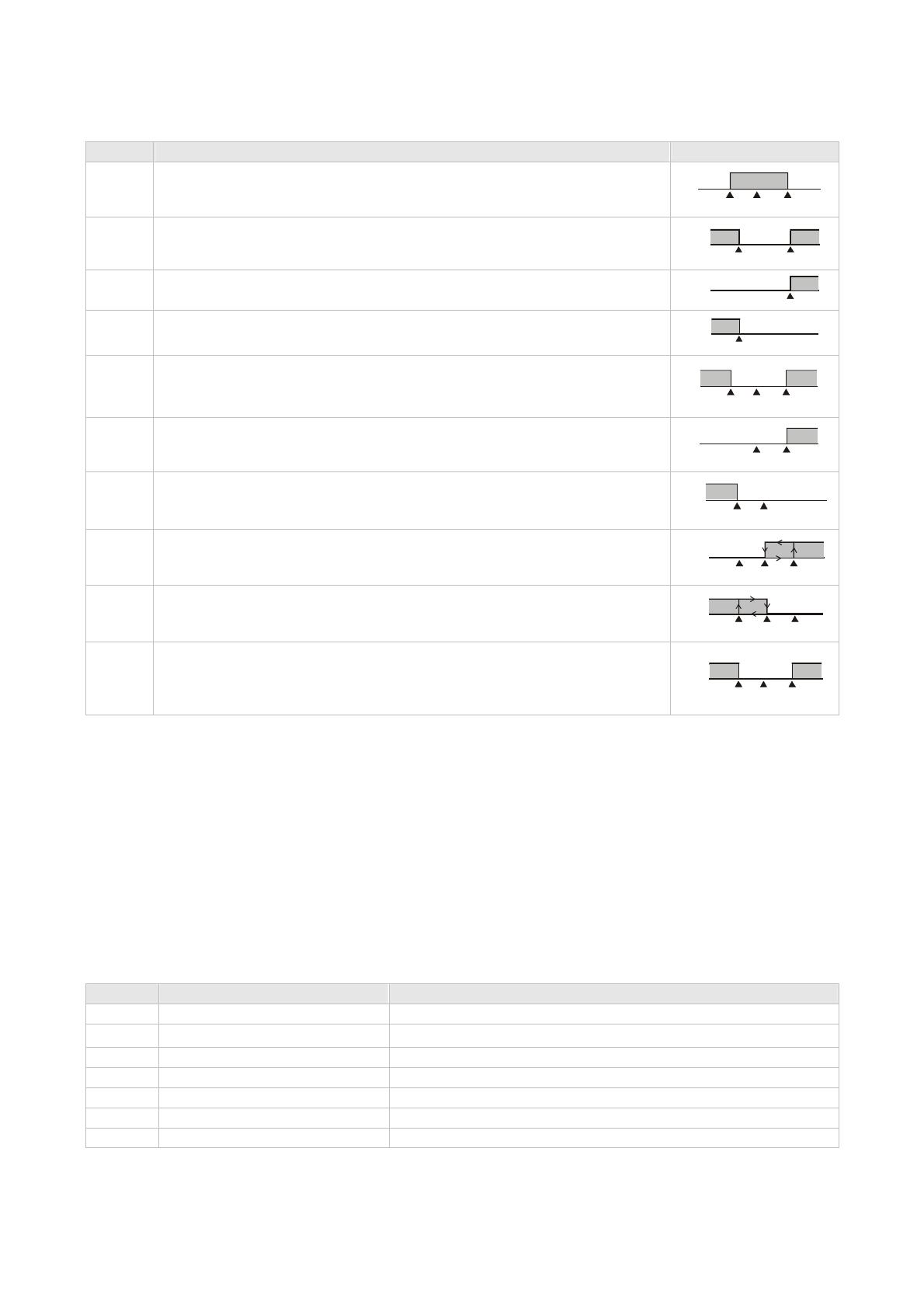
Set value Alarm type Alarm output operation
4
Reverse deviation upper- and lower-limit:
This alarm output operates when PV value is in the range of the setting value SV + (AL-H) and
SV - (AL-L).
ON
OFF
SV
SV-(AL-L) SV+(AL-H)
5
Absolute value upper- and lower-limit:
This alarm output operates when PV value is higher than the setting value AL-H or lower than
setting value AL-L.
ON
OFF
AL-L AL-H
6 Absolute value upper-limit:
This alarm output operates when PV value is higher than the setting value AL-H.
ON
OFF
AL-H
7 Absolute value lower-limit:
This alarm output operates when PV value is lower than the setting value AL-L.
ON
OFF
AL-L
8
Deviation upper- and lower-limit with standby sequence:
This alarm output operates when PV value reaches set value (SV value) and the value is
higher than the setting value SV + (AL-H) or lower than the setting value SV - (AL-L).
ON
OFF
SV
SV-(AL-L) SV+(AL-H)
9
Deviation upper-limit with standby sequence:
This alarm output operates when PV value reaches set value (SV value) and the reached
value is higher than the setting value SV + (AL-H).
SV+(AL-H)
ON
OFF
SV
10
Deviation lower-limit with standby sequence:
This alarm output operates when PV value reaches the set value (SV value) and the reached
value is lower than the setting value SV - (AL-L).
SV-(AL-L)
ON
OFF
SV
11
Hysteresis upper limit alarm output: this alarm output operates if PV value is higher than the
setting value SV + (AL-H). This alarm output is OFF when PV value is lower than the setting
value SV + (AL-L).
ON
OFF
AL-L
SV AL-H
12
Hysteresis lower limit alarm output: this alarm output operates if PV value is lower than the
setting value SV - (AL-H). This alarm output is OFF when PV value is higher than the setting
value SV - (AL-L).
ON
OFF
AL-H AL-L SV
13
CT alarm output:
This alarm operates when the current measured by transformer (CT) is lower than AL-L or
higher than AL-H (This alarm output is available only for the controller with current
transformer).
ON
OFF
AL-L SV AL-H
Note: AL-H and AL-L include AL1H, AL2H and AL1L, AL2L.
With standby sequence: Meaning that the alarm output would be temporarily disabled until the PV value reaches the set value. Then, the
alarm output will operate.
Current Transformer (CT) Function
The Current Transformer (CT) function is used with the alarm output. When using a current transformer (CT) with the controller, change the
corresponding alarm output mode to mode 13 (alarm output set value is 13), then turn to operation mode and set the current lower-limit and
current upper-limit. You can set current alarm range between 0.5A ~ 30A, display resolution is 0.1A and measure accuracy is +/- 0.5A.
Communication Parameters List
Controller offers a RS-485 port for serial communication.
• Supporting transmission speed: 2,400, 4,800, 9,600, 19,200, 38,400bps
• Communication protocol: Modbus (ASCII)
• Non-supported formats: 7, N, 1 or 8, O, 2 or 8, E, 2
• Available communication address: 1 to 255, 0 is broadcast address
• Function code: 03H to read the contents of register (Max. 3 words); 06H to write 1 (one) word into register.
Address Content Explanation
4700H (R) Process value (PV) Measuring unit is 0.1, updated one time in 0.5 second
4701H Set point (SV) Unit: 0.1 (oC or oF)
4702H Upper-limit alarm 1
4703H Lower-limit alarm 1
4704H Upper-limit alarm 2
4705H Lower-limit alarm 2
4706H Upper-limit of temperature range The data content should not be higher than the temperature range


