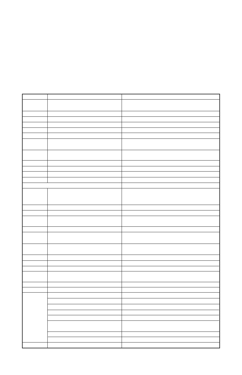
Communication Register List
Communication Parameters List
Controller offers a RS-485 port for serial communication.
1. Supporting transmission speed: 2400, 4800, 9600, 19200, 38400 bps.
2. Communication protocol: Modbus (ASCII).
3. Non-supported formats: 7, N, 1 or 8, O, 2 or 8, E, 2.
4. Available communication address: 1 to 255, 0 is broadcast address.
5. Function code: 03H to read the contents of register (Max. 3 words).
6. 06H to write 1 (one) word into register.
Address Content Explanation
4700H (R) Process value (PV) Measuring unit is 0.1, updated one time
in 0.5 second.
4701H Set point (SV) Unit is 0.1, oC or oF
4702H Upper-limit alarm 1
4703H Lower-limit alarm 1
4704H Upper-limit alarm 2
4705H Lower-limit alarm 2
4706H Upper-limit of temperature range The data content should not be higher than
the temperature range
4707H Lower-limit of temperature range The data content should not be lower than
the temperature range
4708H PB Proportional band 0.1 to 999.9, unit is 0.1
4709H Ti Integral time 0 to 9999
470AH Td Derivative time 0 to 9999
470BH Heating/Cooling hysteresis 0 to 9999
470CH ~ 470FH Reserved
4710H Input temperature sensor type Please refer to the contents of the
“Temperature Sensor Type and
Temperature Range” for detail
4711H Control method 0: PID (default), 1: ON/OFF, 2: manual tuning
4712H Heating/Cooling control cycle 1 to 99 second
4713H Proportional control 0% to 100%
offset error value
4714H Temperature regulation value -999 ~ 999, unit: 0.1
4715H Alarm 1 type Please refer to the contents of the “Alarm
Outputs” for detail
4716H Alarm 2 type Please refer to the contents of the “Alarm
Outputs” for detail
4717H Temperature unit display selection oC: 1 (default), oF: 0
4718H Heating/Cooling control Selection Heating: 0 (default), Cooling: 1
4719H Control Run/Stop setting Run: 1 (default), Stop: 0
471AH Communication write-in selection Communication write in disabled: 0 (default),
Communication write in enabled: 1
471BH Software version W1.00 indicates 0 x 100
4729H AT Setting OFF: 0 (default), ON:1
Code 0 Normal operation (No error)
Code 1 Initial process
Code 2 Initial status (Temperature is not stable)
Code 3 Temperature sensor is not connected
472BH (R) Code 4 Temperature sensor input error
Code 5 Measured temperature value exceeds
the temperature range
Code 6 No Int. error
Code 7 EEPROM Error
4733H CT monitor value Unit is 0.1A
Note: R means “read only” value
Page 16