EBECO Foil Kit and Foil 230 V User manual
- Type
- User manual

SE | MONTERINGSANVISNING
EN | INSTALLATION INSTRUCTIONS
NO | LEGGEANVISNING
FI | ASENNUSOHJE
Foil Kit & Foil 230 V
garantera.ebeco.se
Skapa garantibevis direkt i mobilen

Foil Kit 500
(EB-Therm 500)
Typ av regelering av värmeeffekt/
rumstemperatur (välj en)
Type of heat output/room temp.
control (select one)
Enstegs värmeffekt utan
rumstemperaturreglering
Single stage heat output and no room
temp. control
NEJ
No
Två eller flera manuella steg utan
rumstemperaturreglering
Two or more manual stages, no room
temp. control
NEJ
No
Med mekanisk termostat för
rumstemperaturreglering
With mechanic thermostat
room temp. control
NEJ
No
Med elektronisk rumstemperatur-
reglering
With electronic room temp. control
NEJ
No
Med elektronisk rumstemperatur-
reglering plus dygnstimer
With electronic room temp. control
plus day timer
NEJ
No
Med elektronisk rumstemperatur-
reglering plus veckotimer
With electronic room temp. control
plus week timer
JA
Yes
Andra regleringsmetoder
(flera alternativ kan markeras)
Other control options
(multiple selections possible)
Rumstemperaturreglering med
närvarodetektering
Room temp. control with presence detection
NEJ
No
Rumstemperaturreglering med
detektering av öppna fönster
Room temp. control with open
window detection
JA
Yes
Med möjlighet till ärrstyrning
With distance control detection
JA
Yes
Med anpassningsbar startreglering
With adaptive start control
JA
Yes
Med drifttidsbegränsning
With working time limitation
(operating time limitaion)
JA
Yes
Med svartkroppsgivare
With black bulb sensor
NEJ
No
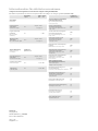
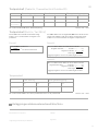
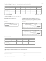
Informationskrav för elektriska rumsvärmare
I enlighet med ekodesignkraven för rumsvärmare enligt förordning EU 2015/1188
Information requirements for electric local space heaters according to eco design, regulation (EU 2015/1188)
EBECO AB
Lärjeågatan 11
SE-415 02 Göteborg, SWEDEN
Phone +46 31 707 75 50
ebeco.com
Beteckning
Symbol
Värde
Value
Enhet
Unit
Värmeeffekt
Heat output
Nominell avgiven
värmeeffekt
Nominal heat output
Pnom
Se spec. sid. 4
See page 14
Lägsta värmeeffekt
(indikativt)
Min. heat output
(indicative)
Pmin 0 kW
Max kontinuerlig
värmeeffekt
Max. continous heat output
Pmax, c
Se spec. sid. 4
See page 14
Tillsatselförbrukning
Auxiliary electricity
consumption
Foil Kit 500
(EB-Therm 500)
Vid nominell avgiven
värmeeffekt
At nominell heat output
elmax
Se spec. sid. 4
See page 14
Vid lägsta värmeeffekt
At min. heat output elmin 0,000 kW
I standby-läge
In stand-by mode elSB 0,000 kW

3
SE
Tack för att du valde Ebeco. Vi hoppas att du kommer att
ha glädje av din golvvärmeanläggning lång tid framöver.
För att garantin ska gälla måste produkten installeras och
handhas enligt denna manual. Det är därför viktigt att du
läser manualen.
Om du har frågor är du naturligtvis alltid välkommen att
kontakta Ebeco. Ring 031-707 75 50 eller skicka ett mail till
[email protected]. Besök gärna ebeco.se för mer
information.
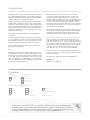
Välkommen
Golvvärmesystemet är en starkströmsanläggning och
skall därför installeras enligt gällande föreskrifter och av
en auktoriserad elinstallatör. För att garantin ska gälla
måste garantibeviset vara korrekt och komplett ifyllt och
underskrivet av auktoriserad elinstallatör.
• Får endast installeras i torra utrymmen.
• Kontrollera att folien är märkt med 230 V och 65 W/m2.
• Folien skall förläggas med kopparbanden nedåt.
• Lägsta installationstemperatur +10 oC.
• Folien ska resistans- och isolationsmätas enligt
anvisningar. Dokumentera värden i vår webbapp
Garantera Ebeco eller i garantibeviset.
• En skiss eller foto över folieförläggningen skall också
finnas dokumenterad.
• Golvbeläggning skall av golvleverantörens anvisningar
vara rekommenderad som lämplig i kombination med
golvvärme.
• Maximalt tillåtet värmemotstånd hos golvmaterialet är
0,16 m2 K/W.
• Värmen ska styras med Ebecos termostater EB-Therm.
• Systemet ska anslutas till 230 V via jordfelsbrytare 30 mA.
• Folien skall skyddas mot mekaniska skador.
Golvläggningen skall utföras omedelbart efter
folieförläggningen.
• Folierna skall täckas med åldringsbeständig plastfolie
minst 0,2 mm före golvläggning.
• Presstång (89 606 90) måste användas för att garantin
ska gälla.
• Maxbelastning/ folie 10 A.
• Folien får inte läggas under fast inredning, som
köksbänkar, garderober, innerväggar o. dyl. eftersom
det ger förhöjd temperatur, ej heller i närheten av t ex
kaminer eller andra värmekällor.
• Isolerande inredning typ tjocka mattor eller sittkuddar
får inte förekomma.
• I rum med trägolv ska alltid funktionen Rums- och
golvtermostat användas.
• Produkten avger <2 % av gränsvärdet för magnetiska fält
enligt EN 62233:2008.
• Isolerskivor jämnar inte ut ojämnheter i underlaget
därav gäller fortsatt golvtillverkarens anvisningar
gällande underlagets ytjämnhet.
Viktigt
Branschriktlinjer för trägolv på golvvärme
Allmänna förutsättningar. Trägolv:
Maximalt tillåten yttemperatur är 27 oC. Detta gäller även
under mattor och möbler.
Övertäckning:
Beakta att vid all övertäckning av trägolv lagda på golvvärme
riskerar man:
• Övertemperatur i trägolvet
• Att temperaturen i rummet blir för låg
Som övertäckning räknas mattor, sängar utan ventilerad
sockel, bokhyllor med täckande botten, köksskåp m.m.

4
• Åldersbeständig plastfolie
• Ebisol 3 mm (89 601 70), Ebisol 6 mm (89 601 72).
Om möjligt välj 6 mm. Förläggningen blir då enklare, snabbare och säkrare.
• Presstång för Ebeco Foil (89 606 90)
• Dubbelisolerad kabel, typ RTK brun (03 766 13) och RTK blå (03 766 03).
• Spiralslang (t ex 89 605 41)
• Fixeringstejp för Ebeco Foil (89 605 46)
• An- Avslutningssats Mini (89 606 79) eller Maxi (89 606 80)
• Termostat EB-Therm
• Jordfelsbrytare
Har du köpt Ebeco Foil på löpmeter behöver du komplettera med
Läs noga igenom hela monteringsanvisningen innan du börjar förläggningen.
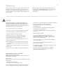
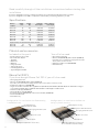
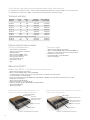
Om du köpt Ebeco Foil Kit - jämför materialet i ditt Foil Kit mot tabellen nedan innan du börjar.
Om du köpt Ebeco Foil 230 V - jämför materialet mot följesedeln innan du börjar.
Artikel/innehåll Bredd
(cm) Längd
(m) Nominell angiven
värmeeffekt Max kont.
värmeeffekt
89 610 20 43 13,5 0,351 kW 0,351 kW
89 610 21 43 18 0,468 kW 0,468 kW
89 610 22 43 22,5 0,585 kW 0,585 kW
89 610 23 43 27 0,702 kW 0,702 kW
89 610 24 43 31,5 0,819 kW 0,819 kW
89 610 26 100 10 0,63 kW 0,63 kW
89 610 27 100 15 0,945 kW 0,945 kW
Kompletteringssats utan termostat för Foil Kit:
89 610 25 43 22,5 0,585 kW 0,585 kW
89 610 28 100 10 0,630 kW 0,630 kW
Specifikationer
Ebeco Foil 230 V
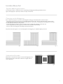
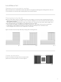
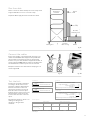
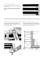
Konstruktion 1 används vid trä-/ laminat-
golv som ytbeläggning
Trä/laminatgolv
(min 7 mm, max 15 mm)
Åldersbeständig plastfolie 0,2 mm
Ebeco Foil 0,3 mm
Ebisol isoleringsskiva 3/6 mm
Befintligt golv (spånskiva eller betong)
Konstruktion 2 används vid plastmatta/
vinyl/heltäckningsmatta som ytbeläggning
Plastmatta/vinyl/heltäckningsmatta
Spontad renoveringsskiva min 5 mm
Åldersbeständig plastfolie 0,2 mm
Befintligt golv (spånskiva eller betong).
Även i kombination med t ex plastmatta.
Ebeco Foil 0,3 mm
Ebisol isoleringsskiva 3/6 mm
Material och tillbehör
• Åldersbeständig plastfolie
• Ebisol 3 mm (89 601 70), Ebisol 6 mm (89 601 72).
Om möjligt välj 6 mm. Förläggningen blir då enklare,
snabbare och säkrare.
• Presstång för Ebeco Foil (89 606 90)
• Jordfelsbrytare
Ingår i förpackningen Du behöver även
• Termostat med givarkabel
• Spiralslang med adapter
• Anslutningsklämmor
• RTK brun
• RTK blå
• Fixeringstejp vit
• Förseglingstejp grön
• Isoleringstejp svart
• Skylt Värmefolie installerad

5
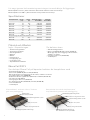
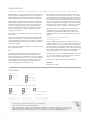
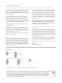
Se till att golvet är fast och fritt från smuts och gammal golvbeläggning. Befintlig plastmatta skall av-
lägsnas då mjukgöraren i plasten på sikt kan lösa upp isolerskivorna.
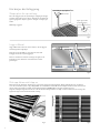
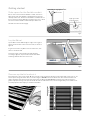
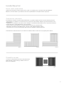
Vid eventuella hinder:
Om det finns ett hinder mitt i vägen, så skall folieförläggningen ske
på följande sätt. Folien skall kapas vinkelrätt och byglas förbi hin-
dret, enligt figur 4.
fig. 2fig. 1 fig. 3
Installera Ebeco Foil
Tag bort befintlig plastmatta
Planering av din förläggning
Gör en exakt skiss på golvet och rita in hur folielängderna skall ligga. Tänk på följande när du ritar skissen:
• Termostaten bör placeras med hänsyn till strömmatningen till termostaten. Placera aldrig termostaten i direkt solljus.
• Folielängderna placeras kant i kant. Folierna skall täcka så stor del av ytan som möjligt men folielängderna bör inte dras
isär, då temperaturskillnaderna blir kännbara.
• Folierna kan läggas lite omlott, dock får avståndet mellan kopparbanden aldrig bli mindre än 5 mm.
• Det är viktigt att få bästa täckning på de ytor där du står, t ex framför köksinredning.
• Planera så att folien förläggs mot yttervägg för att minimera kallras.
Följande tre alternativ, figur 1-3, visar olika möjligheter till förläggning och sammankoppling av folierna.
fig. 4

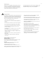
6
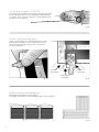
ca 15 cm
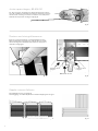
Lägg ut Ebisol
Lägg ut Ebisolskivorna kant i kant. Lämna 1 cm till vägg vid
anslutningssidan enligt fig 6.
Täck hela golvet med Ebisol, även där folie inte skall
förläggas, för att få en jämn bygghöjd.
Fixera isolerskivornas skarvar med tejp, enl fig 6, för att
förhindra rörelser. Skär bort isolermaterialet ovanför
givarslangen.
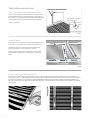
Mät upp folien och klipp av
Rulla ut folien till rätt längd. Avsluta folien 4-5 cm från vägg vid anslutningssidan. Klipp vinkelrätt med en sax utefter
en av de streckade linjerna, se fig 7. Klipp INTE i de svarta fälten. Avståndet från den klippta kanten till det svarta mönst-
ret får aldrig vara mindre än 3 mm. Använd fixeringstejpen (89 605 46) för att tejpa samman foliernas
långsidor. Heltejpa långsidorna fram till ca 15 cm från anslutningsändarna enl fig 8 om du använder 3 mm isolering. Hel-
tejpa hela vägen om du använder 6 mm isolering.
Här börjar din förläggning
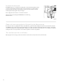
Skapa plats för spiralslang
Fräs eller hugg ett spår för spiralslangen enligt fig 5. Slangen
avslutas mitt under en folie. Gör en mjuk böj för att lättare få
igenom golvgivaren. Skjut in givaren i slangen och tejpa igen
änden.
Dammsug noggrant.
fig. 5
fig. 7 fig. 8
fig. 6
Tejpa igen änden
på spiralslangen
Spiralslang med golvgivare
Termostat
Ca 15 cm
1 cm
www.ebeco.com
www.ebeco.com
www.ebeco.com
www.ebeco.com
www.ebeco.com

7
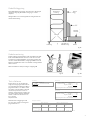
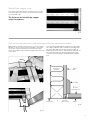
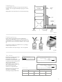
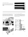
Skär bort för anslutningsklämmorna och frigör utrymme för RTK-kabeln
Om du har 3 mm Ebisol måste du hugga ur i underlaget.
Frilägg ca 1 m av golvet från folien och Ebisolet. Gör
försänkningen enl fig 11. Frigör även utrymme i golvet eller
i väggens nederdel för RTK-kabeln enligt fig 12. Dammsug
noggrant. Återställ Ebisolet och folierna.
Undvik att lägga anslutningarna i gångstråk, tex dörröpp-
ningar. Om anslutningarna måste läggas i gångstråk så skall
anslutningarna och kabel försänkas i golvet då
isolerskivorna komprimeras något på sikt.
Försegla kopparbandet
Försegla kopparbandet med de gröna runda tejpbitarna, se
fig 9. Försegla endast den kortsida som inte skall
anslutas med kabel.
OBS! Folien skall förläggas med
kopparbanden nedåt.
Stämjärn
fig. 11
fig. 9
fig. 10
30 mm
fig. 12
Isolering Vägg
List
Parkett/
Laminat
Utrymme för
kabelkorsning
Träregel
Ebisol
Underlag
Gör markeringar på Ebisolet för anslutningsklämmorna, se
fig 10. Skär bort ca 3 x 6 cm i Ebisolet. Anslutningsklämmorna
och kablarna skall ligga lägre än överkanten på Ebisolet.
Viktigt! Kablar och anslutningsstift får aldrig utsättas för me-
kanisk belastning.

8
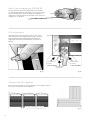
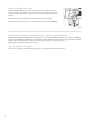
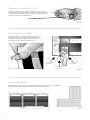
Koppla samman folierna
Parallellkoppla folierna, enligt fig 16.
Vid förläggning i ett vinklat utrymme kan sammankoppling ske enl fig 17.
Montera anslutningsklämmorna
Centrera och fixera klämman över kopparbandet på folien.
Kläm fast klämman med fingrarna, enligt fig 14. Pressa kläm-
man med tången från båda håll i 45º vinkel över det perfore-
rade fältet, enligt fig 15.
fig. 17
fig. 14 fig. 15
fig. 16
fig. 13
Justera presstången, 89 606 90
För att pressningen av klämmorna skall bli korrekt måste tången
vara rätt inställd. På sammanpressad tång får öppningen inte över-
skrida 1,3 mm. Justera genom att lossa skruven och vrida på den
tandade skivan på sidan av tången enligt fig 13.
Kläm här med
tången!
Kläm här med
tången!
OBS! Kläm inte här
Min. 5 mm mellan kopparbanden
1,3 mm

9
fig. 18
Isolering Vägg
List
Parkett/
Laminat
Utrymme för
kabelkorsning
Träregel
Ebisol
Underlag
Kabelförläggning
Fixera RTK-kablarna med tejp eller liknande i det frilagda
utrymmet enligt fig 18. Kabelkorsningar görs i detta
utrymme.
Viktigt! Kablar och anslutningsstift får aldrig utsättas för
mekanisk belastning.
Min. isolationsvärde 10 Mohm. Folien saknar jord. Mät mellan folien och ett jordat föremål. *Tolerans -5 % - +10 %
2034,6
Total längd (m) Teoretiskt resistansvärde
=
230 V, 65 W/m², bredd 43 cm
Formel 1
Testprotokoll
Längd 69 cm-bredd (.............. m) x1,65 =
Längd 43 cm-bredd =
(.............. m)
+
Total längd
Lägg ihop längderna och för in den totala längden i formel 1.
(.............. m)
(.............. m)
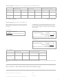
Ebeco Foil 230 V: Räkna om all folie till 43 cm-bredd:
Formel 2
Efter fixering Efter golvbeläggning
Produkt Resistansvärde*
(Ω)
Isolationsvärde*
(MΩ)
Resistansvärde*
(Ω)
Isolationsvärde*
(MΩ)
E-nr: .....................
Installerad längd:
........................ (m)
Formel 3
Längd 100 cm-bredd (.............. m) x2,425 =
Längd 43 cm-bredd =
(.............. m)
+
Total längd
Lägg ihop längderna och för in den totala längden i formel 1.
(.............. m)
(.............. m)
Ebeco Foil 230 V 100 cm: Räkna om all folie till 43 cm-bredd:
Testa folierna
Testa folierna och gör uträkningar
enligt anvisningar i garantibeviset el-
ler använd tjänsten Garantera Ebeco
på garantera.ebeco.se. Räkna ut det
teoretiska resistansvärdet samt mät
resistansen på folierna och för in
värdena i testprotokollet. Jämför det
teoretiska värdet med det uppmätta
värdet. Isolationstesta folierna och
för in värdet i
testprotokollet.
Dokumentera anläggningen med
foto eller skiss enligt anvisningarna
på garantibeviset.
Kabelmontering
Koppla samman folielängderna med de medföljande dub-
belisolerade RTK-kablarna. Avisolera ca 6 mm och stick
in kablarna i kopplingsklämman. Vid endast en kabel viks
den avisolerade delen dubbel, enligt fig 19. Observera att
kablarna är dubbelisolerade och att båda isoleringsskikten
måste tas bort.
Kläm fast kablarna med presstången enligt fig. 20.
fig. 19 fig. 20
6 mm

10
Täck med åldersbeständig plastfolie och lägg ytbeläggning
Täck folierna med åldersbeständig plastfolie minst 0,2 mm t ex Tenotät. Vid skarvning skall plastfolien överlappas minst 200
mm. Lägg därefter ytbeläggningen omgående, enligt konstruktionsbilderna på sid 1. Vissa träslag, speciellt bok och kanaden-
sisk lönn, har större naturliga rörelser och är därför mindre lämpliga för golvvärme. För övrigt skall val av
golvbeläggning ske enligt golvleverantörens anvisningar.
Testa och anslut anläggningen
Testa folierna efter förläggning av ytskikt. För in värdena i testprotokollet eller på garantera.ebeco.se.
Anslut termostaten.
Isolera anslutningsklämmorna
Klipp bitar om 50x25 mm av den svarta isoleringstejpen. Drag av skyddspappret. Centre-
ra en tejpbit under klämman samt en över klämman, enligt fig 21. Tejpen skall sitta minst
5 mm utanför klämmans kanter. Pressa noggrant fast isoleringstejpen med fingrarna.
Observera att klämmorna inte får sträckas eller belastas mekaniskt.
Vid 3 mm Ebisol: Tejpa den resterande delen av folien (ca 15 cm) med fixeringstejpen
(89 605 46).
fig. 21

11
SE
Testprotokoll (Cable Kit, Thermoflex Kit & Multiflex 20)
Min. isolationsvärde 10 MΩ vid min. 500 V testspänning.
Före utläggning Efter fixering Efter golvbeläggning
Produkt Resistansvärde* Isolationsvärde Resistansvärde* Isolationsvärde Resistansvärde* Isolationsvärde
E-nr: .....................
Kabel / Matta 1
E-nr: .....................
Kabel / Matta 2
Testprotokoll (Foil Kit / Foil 230 V)
Elinstallationen utförd av:
...............................................................................
enligt bifogad materialspecifikation.
Datum: ......................................................................
Signatur: ....................................................................
Anläggningen dokumenterad med foto/skiss
Min. isolationsvärde 10 MΩ. Folien saknar jord. Mät mellan folien och ett jordat föremål. *Tolerans -5 % - +10 %
Foil Kit: Räkna ut teoretiskt resistansvärde enligt
formel 1. För in resistansvärdet och längden i test-
protokollet.
2034,6
Total längd (m) Teoretiskt resistansvärde
=
230 V, 65 W/m², bredd 43 cm
Formel 1
Testprotokoll
Längd 69 cm-bredd (.............. m) x1,65 =
Längd 43 cm-bredd =
(.............. m)
+
Total längd
Lägg ihop längderna och för in den totala längden i formel 1.
(.............. m)
(.............. m)
Ebeco Foil 230 V: Räkna om all folie till 43 cm-bredd:
Formel 2
Foil 230 V: Räkna först om längden 69/100 cm folie till 43 cm folie
enligt formel 2. Räkna sedan ut teoretiskt resistansvärde enligt
formel 1. För in resistansvärdet och längden i testprotokollet.
Efter fixering Efter golvbeläggning
Produkt Resistansvärde*
(Ω)
Isolationsvärde*
(MΩ)
Resistansvärde*
(Ω)
Isolationsvärde*
(MΩ)
E-nr: .....................
Installerad längd:
........................ (m)
Formel 3
Längd 100 cm-bredd (.............. m) x2,425 =
Längd 43 cm-bredd =
(.............. m)
+
Total längd
Lägg ihop längderna och för in den totala längden i formel 1.
(.............. m)
(.............. m)
Ebeco Foil 230 V 100 cm: Räkna om all folie till 43 cm-bredd:
*Tolerans -5 % - +10 %

12
Garantivillkor
Cable Kit, Cableflex, Thermoflex Kit, Thermoflex, Foil Kit, Foil 230 V och Multiflex 20
Produkter
Ebeco AB lämnar 12 års garanti för materialfel på värmeka-
bel/folie inklusive medföljande tillbehör och isolerskiva i Ca-
ble Kit, Cableflex, Thermoflex Kit, Thermoflex, Foil Kit, Foil
230 V, Multiflex 20-kabel, hädanefter kallade ”Produkterna”.
Om materialfel skulle uppstå på Produkterna under garan-
titiden förbinder sig Ebeco AB att reparera alternativt byta
Produkterna utan kostnad för köparen. Ebeco AB åtar sig
även att återställa golvet till sitt ursprungliga skick efter
genomförd reparation eller utbyte. För att kunna laga felet
måste köparen ha sparat eller ha tillgång till 1 m² av det
befintliga golvmaterialet.
Ebeco AB ger 5 års produktgaranti för den medlevererade
termostaten.
Garantin blir gällande endast under förutsättning att instal-
lationen av Produkterna är utförd av auktoriserad elinstal-
latör enligt gällande föreskrifter och i enlighet med av Ebeco
utfärdad monteringsanvisning. Samt att någon av nedanstå-
ende krav är uppfyllt:
A) Installationen är utförd med hjälp av och dokumenterad i
Ebecos tjänst Garantera.
Eller
B) Detta garantibevis inklusive testprotokoll är komplett
ifyllt samt tillsammans med materialspecifikation eller
faktura är signerat av den elinstallatör som utfört installatio-
nen. Vidare skall det finnas foton som visar hela Produkterna
efter förläggningen men innan övertäckning, alternativt en
detaljerad skiss med Produkternas ändavslutningar och
skarvar samt golvgivarens exakta placering.
Garantin gäller inte för installationer som har utförts av en
icke auktoriserad elinstallatör alternativt om en icke aukto-
riserad elinstallatör har vidtagit ändringar eller reparationer.
Garantin gäller ej heller om felet har uppstått som ett resul-
tat av användning av felaktigt material och golvkonstruktion
eller som ett resultat av monteringsfel. Inte heller omfattas
skador som uppkommit av skadegörelse, brand, åsknedslag,
vattenskada eller skador orsakade av vårdslöshet, onormalt
användande eller som ett resultat av en olyckshändelse.
Om garantin skall tas i anspråk gäller följande: Ebeco AB
skall meddelas innan någon åtgärd vidtas. Vidare skall
garantibevis med tillhörande faktura på installation eller
materialspecifikation samt ifyllt och signerat testprotokoll
uppvisas.
Förläng garantitiden till 25 år
med Garantera
I Ebecos digitala tjänst Garantera dokumenteras alla vär-
mekabelinstallationer på ett enkelt, säkert och strukturerat
sätt. En installation som är gord med hjälp av Garantera
får automatiskt en förlängd garantitid till 25 år för material-
fel. Den utökade garantin gäller endast under förutsättning
att produkten installerats tillsammans med tillämpbar styr-
ning samt har utförts av en auktoriserad elinstallatör.
Från Garantera e-postas ett digitalt Garantibevis till bruka-
ren, som denne därefter ansvarar för att spara och kunna
uppvisa vid ett eventuellt garantiärende.
På termostaten gäller fortsatt 5 års produktgaranti.
EBECO AB
Martin Larsson, VD
Produkt: *i kombination med:
Foil Kit 500 EB-Therm 55
Foil 230 V* EB-Therm 205
EB-Therm 500
EB-Therm 800
Är installerad i följande utrymmen:
Hall Vardagsrum Annat:
Kök Sovrum
Våtrum Uterum
Artikelnummer: Längd/storlek: Effekt/spänning:
Tips!
Förlängd garantitid till 25 år och enklare
dokumentering med Garantera
Vill du slippa att fylla i och hålla reda på de här sidorna? Garantera är en tjänst som gör det enklare för dig som
auktoriserad installatör. Med tjänsten dokumenterar du mätdata, sparar foton av installationen och skapar ett
digitalt garantibevis att skicka till kunden. Läs mer om tjänsten och kom igång på garantera.ebeco.se.

13
Thank you for choosing Ebeco. We hope that you will use
and enjoy your underfloor heating system for many years
to come. For the warranty to be valid, the product must
be installed and handled as indicated in this manual. It is
therefore important that you read the manual.
If you have any questions, please contact us at Ebeco. Call
+46 31-707 75 50 or send an e-mail to [email protected].
Feel free to visit ebeco.com for more information.
Welcome
The underfloor heating system is a high voltage system and
must thus be installed according to applicable regulations
and by an authorised electrician. For the warranty to apply,
the warranty certificate must be correctly and completely
filled in, and signed by an authorised electrician.
• May only be installed in dry areas.
• Check that the foil is labelled for 230V and 100 W/m2 or
65 W/m2.
• The foil must be laid with the copper strips facing down.
• Do not install when the temperature is below +10 oC.
• The foil must be measured for resistance and isolation
per the instructions. Document the values on the
warranty certificate.
• There must be either a diagram or photo of the routing
documented.
• Floor covering shall be recommended by the floor
supplier’s instructions as suitable in combination with
underfloor heating.
• Maximum thermal resistance of the flooring material is
0.16 m2K/W.
• Heating must be regulated with Ebeco’s EB-Therm
thermostats.
• The system must be connected to 230 V via a 30 mA
residual current operated circuit-breaker.
• The foil must be protected from damage. The floorcovering
must be laid immediately after the foil has been laid.
• The foils must be covered with non-ageing plastic film,
at least 0.2 mm, before the floor is laid.
• Crimping tool (89 606 90) must be used, otherwise the
warranty will be invalid.
• The maximum load per foil is 10 A.
• The foil must not be run under stationary furnishings,
such as kitchen counters, closets, inner walls, etc.
because this produces elevated temperatures, and not
close to stoves or other heat sources.
• Insulating interior furnishings such as thick carpets or
floor cushions must not be used.
• The product emits <2 % of the magnetic field limit
according to EN 62233:2008.
• Insulation boards do not even out unevenness in the
surface, so the floor manufacturer’s instructions
regarding the surface smoothness still apply.
Important
EN
Industry guidelines for wooden floors on
underfloor heating
General conditions. Wooden floors:
The maximum permissible surface temperature is 27 oC.
This also applies under carpets and furniture.
Coverage:
Note that with all covering of wooden floors laid on
underfloor heating, there is a risk:
• Overtemperature in the wooden floor
• That the temperature in the room becomes too low
Carpets, beds without ventilated plinth, bookshelves with a
covering bottom, kitchen cabinets, etc. are covered.

14
• Non-ageing plastic film
• Ebisol 3 mm (89 601 70), Ebisol 6 mm (89 601 72).
If possible, choose 6 mm. The laying then becomes easier, faster och more secure.
• Crimping tool Ebeco Foil (89 606 90)
• Single core double-insulated cable, eg RTK brown (03 766 13) and RTK blue (03 766 03). As an alternative a single
core single insulated cable combined with a flexible conduit pipe could be used.
• Flexible conduit pipe (89 605 41)
• Fixing tape Ebeco Foil (89 605 46)
• Connection kit Mini (89 606 79) or Connection kit Maxi (89 606 80)
• Thermostat EB-Therm
• Earth fault relay
If you have bought Ebeco Foil 230 V you will also need:
Read carefully through all the installation instructions before starting the
installation
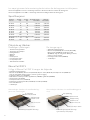
If you have bougt Ebeco Foil Kit -compare the material in your kit with the table below before you start.
If you have bougt Ebeco Foil 230 V -compare the material with your packing slip before you start.
Ebeco Foil 230 V
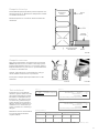
Configuration 1 is used where the floorcovering
is wood/laminate
Configuration 2 is used where the floor co-
vering is plastic matting
Wood/laminate floors
(min 7 mm, max 15 mm)
Non-ageing plastic film 0,2 mm
Ebeco Foil 0,3 mm
Ebisol 3/6 mm
Existing floor (chipboard or concrete floor)
Plastic/vinyl floor covering
Tongued woodenboard min 5 mm
Non-ageing plastic film 0,2 mm
Existing floor (chipboard or concrete floor)
Also in combination with plastic matting
Ebeco Foil 0,3 mm
Ebisol 3/6 mm
Article/
content
Width
(cm) Length
(m) Nominell
heat output Max. continous
heat output
89 610 20 43 13,5 0,351 kW 0,351 kW
89 610 21 43 18 0,468 kW 0,468 kW
89 610 22 43 22,5 0,585 kW 0,585 kW
89 610 23 43 27 0,702 kW 0,702 kW
89 610 24 43 31,5 0,819 kW 0,819 kW
89 610 26 100 10 0,63 kW 0,63 kW
89 610 27 100 15 0,945 kW 0,945 kW
Supplementary set without thermostat for Foil Kit:
89 610 25 43 22,5 0,585 kW 0,585 kW
89 610 28 100 10 0,630 kW 0,630 kW
Specifications
Material and accessories
• Non-ageing plastic film
• Ebisol 3 mm (89 601 70), Ebisol 6 mm (89 601 72).
If possible, choose 6 mm. The laying then becomes
easier, faster och more secure.
• Crimping tool Ebeco Foil (89 606 90)
• Earth fault relay
Included in the pack You will also need
• Thermostat with sensor cable
• Spiral tube with adapter
• Terminals
• RTK brown
• RTK blue
• Fixing tape white
• Sealing tape green
• Insulating tape black
• Sign heatingfoil installed

15
Make sure that the floor is firm and free from dirt and old floorcovering material. Existing plastic matting must be removed,
since the plasticiser in the plastic may eventually dissolve the insulation boards.
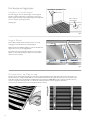
If there are obstacles:
If there is an obstacle in the way, cut the foil square and fit
jumper wires around the obstacle, as shown in figure 4.
fig. 2fig. 1 fig. 3
Install Ebeco Foil
Remove any existing plastic matting.
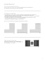
Planning how to lay the foil
Make an accurate sketch of the floor and draw the positions of the lengths of foil. Points to think of when drawing the sketch:
• The position of the thermostat should take account of the power supply. Do not position the thermostat where it will be in
direct sunlight at any time.
• The lengths of foil must be butted edge-to-edge. The foils must cover as large an area as possible, but the lengths of foil
must not be pulled apart, since the differences in temperature will be noticeable.
• The foils may be laid slightly overlapping, but the distance between the copper strips must never be less than 5 mm.
• It´s important to ensure optimum cover where you will often stand, for example in front of the kitchen units.
• To avoid draughts, plan for the foils to be laid right up to outside walls.
Figures 1 to 3 below show various possible ways of laying and connecting the foils.
fig. 4

16
Measure up the foil and cut it
Roll out the foil to the correct length. On the connection side, end the foil about 4-5 cm from the wall. Using scissors, cut
the foil square along the broken lines, as shown in figure 7. DO NOT cut into the black areas. The distance from the cut
edge to the black area must never be less than 3 mm. Use fixing tape (89 605 46) to tape the long sides of the foil to-
gether. Fully tape the long sides up to about 15 cm from the ends of the foils, as shown in figure 8 if you use 3 mm insula-
tion. Fully tape the whole way if you use 6 mm insulation.
Lay the Ebisol
Lay the Ebisol sheets butted edge-to-edge. Leave a gap of
about 1 cm at the wall on the connection side, as shown in
figure 6.
To get a level surface, lay Ebisol over the entire floor, even
where no foil will be laid.
Secure the joints of the insulation boards with tape,
according to figure 6, to prevent movement. Cut off the
insulating material above the sensor hose.
Getting started
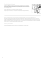
Make space for the flexible conduit
Cut or chase a channel for the flexible conduit, as shown in
figure 5. The end of the flexible conduit must be positioned
centrally under a foil. The bend in the flexible conduit must not
be too sharp or it will be dicult to insert the floor sensor. Feed
the sensor into the flexible conduit and tape off the end.
Vacuum-clean the area thoroughly.
ca 15 cm
fig. 5
fig. 7 fig. 8
fig. 6
Tejpa igen änden
på spiralslangen
Spiralslang med golvgivare
Termostat
Ca 150 cm
ca 15 cm
1 cm
www.ebeco.com
www.ebeco.com
www.ebeco.com
www.ebeco.com
www.ebeco.com

17
Cut out for the terminals and make space for the connection cable
If you are using 3 mm Ebisolyou will have to cut out the
floor. Expose about 1 metre of the floor by folding back
the foil and the Ebisol. Cut out as shown in figure 11.
Make a space in the floor or at the bottom of the wall for
the connection cable, as shown in figure 12. Vacuum-
clean the area thoroughly. Put back the Ebisol and the
foils.
Seal off the copper strip
Seal off the copper strip with the round green pieces of tape,
as shown in figure 9. Seal only the short side that will not be
connected with cable.
The foil must be laid with the copper
strips facing down.
Chisel
fig. 11
fig. 9
fig. 10
30 mm
fig. 12
Insulation Wall
Strip
Wooden/
laminate floors
Cavity for
cable crossing
Joist
Ebisol
Existing floor
Mark the Ebisol where the terminals will go, as shown in figure
10. Make a cutout of about 3 x 6 cm in the Ebisol. The termi-
nals and the cables should be placed lower than the upper
surface of the Ebisol. Important! Never apply mechanical load
to the cables.

18
Connect the foils together
Connect the foils together as shown in figure 16. In an L-shaped room, the
foils can be connected as shown in figure 17.
Fit the terminals
Slip the terminal on to the foil and centre it on the copper
strip. Squeeze the terminal firmly with your fingers as shown
in figure 14. Crimp the terminal from both sides at an
angle of 45º across the perforated part, as shown in fi-
gure 15.
fig. 17
fig. 14 fig. 15
fig. 16
fig. 13
Adjust the crimping tool, 89 606 90
For the terminals to be properly crimped, the pliers must be
correctly adjusted. When the crimping tool is closed, the opening
must not be larger than 1.3 mm. To adjust the crimping tool,
unfasten the screw and turn the toothed disc on the side of the
crimping tool; see figure 13.
1,3 mm
Min. 5 mm between the copper strips
Warning! Don´t
press here!
Press with the
tool here!
Press with the
tool here!

19
Test report
After fixing After covering floor
Product Resistance value*
(Ω)
Insulation value*
(MΩ)
Resistance value*
(Ω)
Insulation value*
(MΩ)
E-number: .....................
Installed length:
........................ (m)
Min. insulation value 10 Mohm. The foil is unearthed. Measure between the foil and an
earthed object.
*Tolerance -5 % to +10 %
fig. 18
Insulation Wall
Strip
Wooden/
laminate floors
Cavity for
cable crossing
Joist
Ebisol
Existing floor
Run the cable
Fix the connection cables with tape etc in the cavity shown
in figure 18. Cables can cross over in this cavity.
Important! Never apply mechanical load to the cables.
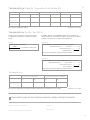
Test the foils
Test the foils and make calculations
according to the directions in the
guarantee certificate. Calculate the
theoretical resistance value and
measure the resistance of the foils.
Enter the values in the test report.
Compare the theoretical value to the
measured value. Isolation test the
foils and enter the value in the test
report.
Document the facility on photo or on
drawing according to the
directions in the guarantee
certificate.
Connect the cables
Connect the lengths of foil together with the single-core
double-insulated RTK cables supplied. Strip off about 6
mm of insulation and insert the wire into the terminal.
If there is only one cable, bend the stripped wire double, as
shown in figure 19. NOTE that the cables are double-insula-
ted and that both insulation layers has to be removed.
Crimp the terminal to the cable with the crimping tool as
shown in figure 20.
fig. 19 fig. 20
6 mm
Length of 69 cm width (.............. m) x1.65 =
Formula
2
(.............. m)
+
Total length
Add up the lengths and enter the total length in formula 1.
(.............. m)
(.............. m)
Ebeco Foil 230 V: Convert all foil to 43 cm width:
Length of 43 cm width =
Length of 100 cm width (.............. m) x2.425 = (.............. m)
+
Total length
Add up the lengths and enter the total length in formula 1.
(.............. m)
(.............. m)
Ebeco Foil 230 V 100 cm: Convert all foil to 43 cm width:
Length of 43 cm width =
Formula 3
Formula 1
2034.6
Total length (m) Theoretical resistance value
=
230 V, 65 W/m², width 43 cm
1322.5
Total length (m) Theoretical resistance value
=
230 V, 100 W/m², width 43 cm

20
Cover with non-ageing plastic film and lay the floorcovering
Cover the foils with non-ageing plastic film, at least 0,2 mm, eg Tenotät. When adding the next piece of plastic film overlap at
least 200 mm. Then lay the floorcovering immediately, in accordance with the arrangements illustrated on page 1. Some kinds
of wood, especially beech and Canadian maple, exhibit more natural movement and are therefore not so suitable for underfloor
heating. The floorcovering should be chosen with the guidance of the flooring supplier.
Test and connect the installation
After laying the floorcovering, test the foils. Enter the values in the test report. Connect the thermostat.
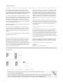
Insulate the terminals
Cut 50x25 mm pieces of the black insulating tape. Pull off the backing paper. Centre
one piece of tape under the terminal and one over the terminal, as shown in figure
21. The tape must extend at least 5 mm beyond the end of the terminal. Press the
insulating tape firmly together with your fingers.
Do not apply mechanical strain or load to the terminals.
Apply the white tape (Fixing tape 89 605 46) to the remaining
15 cm of the foil.
fig. 21
Page is loading ...
Page is loading ...
Page is loading ...
Page is loading ...
Page is loading ...
Page is loading ...
Page is loading ...
Page is loading ...
Page is loading ...
Page is loading ...
Page is loading ...
Page is loading ...
Page is loading ...
Page is loading ...
Page is loading ...
Page is loading ...
Page is loading ...
Page is loading ...
Page is loading ...
Page is loading ...
Page is loading ...
Page is loading ...
Page is loading ...
Page is loading ...
-
 1
1
-
 2
2
-
 3
3
-
 4
4
-
 5
5
-
 6
6
-
 7
7
-
 8
8
-
 9
9
-
 10
10
-
 11
11
-
 12
12
-
 13
13
-
 14
14
-
 15
15
-
 16
16
-
 17
17
-
 18
18
-
 19
19
-
 20
20
-
 21
21
-
 22
22
-
 23
23
-
 24
24
-
 25
25
-
 26
26
-
 27
27
-
 28
28
-
 29
29
-
 30
30
-
 31
31
-
 32
32
-
 33
33
-
 34
34
-
 35
35
-
 36
36
-
 37
37
-
 38
38
-
 39
39
-
 40
40
-
 41
41
-
 42
42
-
 43
43
-
 44
44


EBECO Foil Kit and Foil 230 V User manual
- Type
- User manual
Ask a question and I''ll find the answer in the document
Finding information in a document is now easier with AI
in other languages
Related papers
Other documents
-
Steba CH 1 ECO User manual
-
-
Philips BRL170/00 User manual
-
 MUUT-TUOTEMERKIT EB8960473 Assembly Instructions
-
Hitachi C 15FB Handling Instructions Manual
-
Zanussi ZI921/8FF User manual
-
Elma Instruments BM251s User manual
-
AEG Electrolux ERO2924 User manual
-
Electrolux ERN3122 User manual
-
