Page is loading ...

18-DIN
DUAL COLOUR DISPLAY
TEMPERATURE INDICATOR
Product Manual
59135-5

HOW TO USE THIS MANUAL
This manual comprises two volumes:

1
8-DIN DUAL COLOUR DISPLAY
TEMPERATURE INDICATOR
Product Manual
Contents - Volume I
1OPERATION MODE1-1
1.1FRONT PANEL1-1
1.2PARAMETER SEQUENCE1-2
1.3 INPUT OVER-RANGE OR UNDER-RANGE1-3
1.4SENSOR BREAK 1-3
1.5CHANGING AN ALARM VALUE1-3
1.6 RESETTING A LATCHED ALARM1-4
1.7ALARM HYSTERESIS1-4
1.8 SUMMARY OF PARAMETER IDENTIFIERS (SECONDARY DISPLAY)1-4
2PROGRAM MODE2-1
2.1ENTRY/EXIT2-1
2.2PARAMETER SELECTION2-1
2.3 EDITING THE DISPLAYED PARAMETER (EDIT MODE)2-2
2.4PARAMETER SEQUENCE2-3
3SERIAL COMMUNICATIONS 3-1
3.1DATA FORMAT/BAUD RATE3-1
3.2PROTOCOL3-1
3.3MESSAGE FORMAT3-1
3.4ERROR CONDITIONS3-4
OM090-FM Volume I(iii)
59135

1OPERATION MODE
This mode covers day-to-day operation of the Indicator.
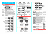
1.1FRONT PANEL
1-1Volume IOM090-1
59135
Key/Display/IndicatorFunction
Down key (Ú)In Edit Mode, decrements the flashing digit in the Primary Display.
Scroll key (Ø)Puts Indicator into Edit Mode; in Edit Mode, selects digit to be altered
(selected digit is flashing) in Primary Display. Wrap-around occurs from
right-most digit to left-most digit.
Program Key (PGM )Selects parameter to be viewed/edited. In Edit Mode, confirms changed
parameter value.
Reset key (RST)If the process variable is displayed, resets the latched Alarm 1. If the
Maximum (High) Value, Minimum (Low) Value or Alarm 1 Elapsed Time is
displayed, resets the displayed parameter.
Down (Ú) and Scroll
(Ø) keysIf pressed simultaneously in Edit Mode, will abort the Edit operation and
will restore the parameter to its initial value.
Primary DisplayNormally displays the process variable value. Displays other Operation
Mode parameters when the Program (PGM) key is used. If the Help
Facility is enabled (see Subsection 2.4), this display shows the parameter
description for three seconds before displaying the parameter value.
Secondary DisplayShows a single-character identifier for the parameter value being
displayed (blank for process variable).
OP1 indicator ON when Alarm 1 is active.
OP2 indicatorON when Alarm 2 is active.

1.2PARAMETER SEQUENCE
OM090-1Volume I1-2
59135

1.3INPUT OVER-RANGE OR UNDER-RANGE
If the input becomes over-range or under-range, the primary display will show:
The display will disappear when the input returns within the input scale range.
1.4SENSOR BREAK
This indicates that there is a break in the input sensor circuit.
1.5CHANGING AN ALARM VALUE
1-3Volume IOM090-1
59135

1.6RESETTING A LATCHED ALARM
If Relay 1 is configured to act as a latched Alarm 1 relay, when this alarm is
active, it can be reset by selecting the process variable display and then pressing
the Reset (RST) key. The alarm will not be reset if the alarm condition exists at the
time reset is attempted.
1.7ALARM HYSTERESIS
The Alarm Hysteresis parameter applies a hysteresis band on the “safe” side of the
Alarm value. The effect of the hysteresis value (a percentage of input span) on the
operation of the different types of alarm is illustrated below:
1.8SUMMARY OF PARAMETER IDENTIFIERS
(SECONDARY DISPLAY)
OM090-1Volume I1-4
59135
Secondary DisplayDisplayed Parameter
BlankProcess variable
Maximum (High) value
Minimum (Low) value
Alarm 1 Elapsed Time
Alarm 1 value
Alarm 1 Hysteresis value
Alarm 2 value
Alarm 2 Hysteresis value

2PROGRAM MODE
2.1ENTRY/EXIT
Use the Program (PGM) key in the same way to exit Program Mode (i.e. return to
Operation Mode).
2.2PARAMETER SELECTION
2.2.1With Help Facility Enabled
2-1Volume IOM090-2
59135

2.2.2With Help Facility Disabled
2.3EDITING THE DISPLAYED PARAMETER (EDIT MODE)
OM090-2Volume I2-2
59135

2.4PARAMETER SEQUENCE
The Program Mode parameter sequence is as follows:
2 -3Volume IOM090-2
59135
Parameter
Description
(Primary
Display)
ParameterDescription Adjustment Range
Re-
transmission
Scale
Minimum
The lower end of the linear
scale for the
re-transmission output,
expressed as the value
corresponding to the
minimum output signal.
−19999 to 99999−19999
Re-
transmission
Scale
Maximum
The upper end of the
linear scale for the
re-transmission output,
expressed as the value
corresponding to the
maximum output signal.
−19999 to 9999999999
Process
Variable
Offset
Corrects a known offset of
the input in order to
display more accurately
the process value.
− 19999 to 999990.00
Input Filter
Time
Constant
Filters the input over a
user-definable time period
to minimise the effect on
the process variable of
any extraneous impulses
0.0 (OFF) to 100.02.0
Comm-
unications
Address
The unique serial
communications address
of the instrument.
1 to 991
Baud Rate Serial communications
speed 1200, 2400, 4800 or 9600 4800
Display
Colour
Change
Defines the colour of the
primary and secondary
displays prior to/after the
preset value (e.g. Alarm
level) is reached.
Red
Green
Green
to Red
Red to
Green
Green to
Red
Alarm LockEnables/disables the
changing of alarm values
via the front panel.
Enabled
Disabled
Enabled
Help PromptDetermines whether the
Primary Display shows the
parameter description for
3 seconds before a
parameter value is shown.
Yes
No
Yes

3SERIAL COMMUNICATIONS
The Serial Communications option is a standard RS485 communications link. Up to
32 standard RS485 loads may be presented to a single loop on this link. Each
Indicator presents ¼ standard, therefore up to 128 may be connected to a single
loop (ignoring the load presented by the master device). However, addresses are
restricted to the range 1 to 99.
3.1DATA FORMAT/BAUD RATE
Data format is fixed at one start bit, seven data bits, 1 parity bit (even parity) and
1 stop bit i.e. a 10-bit data word. Baud rates supported are 1200, 2400, 4800 and
9600. The half-duplez line turn-round time is fixed at 6ms regardless of Baud rate.
The maximum inter-character delay is 120ms. The No Reply timeout is 2 seconds.
Data is expressed as a five-digit signed hexadecimal number in which the
following characters are permitted:
0 1 2 3 4 5 6 7 8 9 A B C D E F
Note that all the non-numeric characters are upper case. The detection of any
characters other than these will be regarded as a syntax error. Where a value
carries a decimal point, the point position is implicit and the responsibility for
interpreting it lies with the user.
3.2PROTOCOL
The protocol operates on a single master basis only. All communication is initiated
by the master device.
The communications addresses available are in the range 1 - 99. Address 0 is
used for broadcast Parameter Write operation messages. When a message is
broadcast, the receiving instruments will attempt to implement the instruction but
will not reply.
3.3MESSAGE FORMAT
Each message starts with a Start of Message character (L) and finishes with an End
of Message character (*). A reply from the addressed instrument will contain either
a positive acknowledgement or a negative acknowledgement. A positive
acknowledgement has the character A immediately preceding the End of
Message character; a negative acknowledgement has the character N
immediately preceding the End of Message character.
There are three message formats; they permit instrument identification, Parameter
Read operations and Parameter Write operations.
OM090-3Volume I3-1
59135

3.3.1Form 1 Message
The master device sends a Form 1 message to ascertain whether a specific
communications address is occupied by an instrument. If there is an instrument at
that address, a reply (with a positive acknowledgement) is received. If there is no
instrument at that address or if there is a communications link failure, no reply is
received. The message from the master device is of the form:
Laa??*
where aa is the address (a two-digit hexadecimal number). The reply from the
addressed instrument is of the form:
Laa?A*
where aa is the same address as in the received message.
3.3.2Form 2 Message
This message implements a Parameter Read operation. The message from the
master device is of the form:
Laap?*
where aa is the address (a two-digit hexadecimal number)
p is a single-character parameter identifier (see Table 3-1)
The reply, if the Parameter Read operation is successful, is of the form:
LaapnnnnnA*
where aa is the same address as in the received message
p is a single-character parameter identifier (see Table 3-1)
nnnnn is the data (a five-digit hexadecimal number)
If the specified parameter is invalid (e.g. not applicable to the addressed
instrument), the reply is of the form:
Laap00000A*
where aa is the same address as in the received message
p is a single-character parameter identifier (see Table 3-1)
3-2Volume IOM090-3
59135

3.3.3Form 3 Message
This message implements the Parameter Write operation either on a single
addressed instrument (address in the range 1 - 99) or broadcast to all instruments
connected to the master device (i.e. using address 00). Note that, with the
broadcast message, each slave instrument does not generate a reply. The
message from the master device is of the form:
Laapnnnnn*
where aa is the address (a two-digit hexadecimal number)
p is a single-character parameter identifier (see Table 3-1)
nnnnn is the value to be written (a five-digit hexadecimal
number)
The reply for a successful Parameter Write operation is of the form:
LaapnnnnnA*
where aa is the same address as in the received message
p is a single-character parameter identifier (see Table 3-1)
nnnnn is the value written (a five-digit hexadecimal number). In
cases in which this parameter does not exist or is not
applicable for the slave instrument, this value is 00000.
Iif a valid parameter is specified with an invalid value or an error condition is
encountered, the reply is of the form:
LaapnnnnnN*
where aa is the same address as in the received message
p is a single-character parameter identifier (see Table 3-1)
nnnnn indicates the error condition:
OM090-3Volume I3-3
59135
ValueError Condition
FFFFFValue under-range
7FFFFValue over-range
7FFFESensor Break detected
00001 Read Only parameter
00000Illegal value

3.4ERROR CONDITIONS
If a slave device detects a syntax error or parity error, it will not reply to the
message; the master device should make up to two retries, applying the
two-second No Reply timeout in each case.
Parameter Read operations with parameter identifiers which are in the legal
range but which are not applicable to the addressed instrument will have no
effect on any parameter values and a positive acknowledgement will be
returned.
Parameter Write operations with parameter identifiers which are outside the legal
range will be considered to be syntax errors; no reply will be generated.
Parameter Write operations in which the specified parameter is valid but the
specified value is invalid will generated a negative acknowledgement.
3 -4Volume IOM090-3
59135
Identifier Hex.ParameterAdjustment Range
:3AProcess VariableRead Only (−19999 to 9999)
<3CMaximum Process VariableRead Only (−19999 to 9999)
=3D Minimum Process VariableRead Only (−19999 to 9999)
>3E Elapsed Alarm 1 TimeRead Only (0 to 60000)
@40 Reset Max. PVWrite resets; Read always 0
A41Reset Min. PVWrite resets; Read always 0
B42Reset Elapsed Alarm 1 TimeWrite resets; Read always 0
D44Reset Latched Alarm 1Write resets; Read always 0
E45Alarm 1 valueRange Max. To Range Min.
F46 Alarm 2 value Range Max. To Range Min.
]5D Re-transmitted Scale Min.−19999 to Re-trans. Scale Max.
^5E Re-transmitted Scale Max. Re-trans. Scale Min. To 99999
_5FProcess Variable Offset0 to Range Span
‘60Input Filter0 to 1000 (0.0 to 100.0s)
a61Colour0 to 3 (0 = Red, 1 = Green,
2 = Green/Red, 3 = Red/Green)
b62Alarm Lock0 (lock enabled), 1 (lock disabled)
c63Help level0 (Help enabled), 1 (Help disabled)
Table 3 -1Parameter Identifiers and Adjustment Ranges

1
8-DIN DUAL COLOUR DISPLAY
TEMPERATURE INDICATOR
Product Manual
Contents - Volume II
The procedures described in this Volume must be undertaken only by
technically-competent servicing personnel.
1INSTALLATION1-1
1.1UNPACKING 1-1
1.2PANEL-MOUNTING1-1
1.3CONNECTIONS AND WIRING1-3
2INTERNAL LINKS AND SWITCHES2-1
2.1REMOVING THE INDICATOR FROM ITS HOUSING2-1
2.2REMOVING/REPLACING THE RELAY 2/LINEAR OUTPUT OPTION PCBs2-3
2.3REMOVING/REPLACING THE RS485 SERIAL COMMUNICATIONS
OPTION PCB/DIGITAL INPUT OPTION PCB2-3
2.4REPLACING THE INSTRUMENT IN ITS HOUSING2-4
2.5SELECTION OF LINEAR (RE-TRANSMISSION) OUTPUT RANGE2-4
3CONFIGURATION MODE3-1
3.1ENTRY/EXIT3-1
3.2PARAMETER SELECTION3-1
3.3 EDITING THE DISPLAYED PARAMETER3-2
3.4PARAMETER SEQUENCE3-3
4SERIAL COMMUNICATIONS - CONFIGURATION MODE4-1
PM090-FM Volume II(i)
59135

Appendices
APRODUCT SPECIFICATIONA-1
A.1DISPLAYA-1
A.2SENSOR INPUTA-1
A.3DIGITAL INPUT (OPTION)A-3
A.4TRANSISTOR OUTPUTSA-3
A.5 RELAY 1 OUTPUT A-3
A.6RELAY 2 OUTPUT (OPTION)A-4
A.7LINEAR (RE-TRANSMITTED PV) OUTPUT (OPTION)A-4
A.8SERIAL COMMUNICATIONS (OPTION)A-4
A.9 PERFORMANCEA-5
A.10ENVIRONMENTALA-7
A.11PHYSICALA-7
(ii)Volume IIPM090-FM
59135

1. Remove the Indicator from its packing. The indicator is supplied with a
panel gasket and push-fit fixing strap. Retain the packing for future use.
2. Examine the delivered items for damage or deficiencies. If any is found,
notify the carrier immediately.
1.2PANEL-MOUNTING
The panel on which the Indicator is to be
mounted must be rigid and may be up to
6mm (0.25 inches) thick. The cut-out
required for a single Indicator is shown in
Figure 1-1. Several indicators may be
mounted side-by-side in a single cut-out.
For n Indicators mounted side-by-side,
the cut-out dimensions would be (48n - 4)
millimetres or (1.89n - 0.16) inches. The
main dimensions of the Indicator are
shown in Figure 1 -2 .
The panel-mounting procedure is shown in Figure 1 -3 .
CAUTION: Do not remove the panel gasket, as this may result in
inadequate clamping of the instrument in the panel.
PM090-1Volume II1-1
59135
Figure 1-1Panel Cut-out
Figure 1-2Main Dimensions
1 INSTALLATION
1.1 UNPACKING
WARNING: This product can expose you to chemicals including arsenic, which is known to the
State of California to cause cancer. For more information go to www.P65Warnings.ca.gov


PM090-1Volume II1-3
59135
Figure 1-4Rear Terminal Connections
Use copper conductors (except on T/C input)
Cable rating 80°C min
Single strand wire gauge: Max 1.2mm
(18SWG)

1.3.1Mains (Line) Supply
The Indicator will operate on 90 - 264V AC 50/60Hz mains (line) supply. The power
consumption is approximately 4 watts.
CAUTION: This equipment is designed for installation in an enclosure
which provides adequate protection against electric shock. Local
regulations regarding electrical installation should be rigidly
observed. Consideration should be given to prevention of access to
the power terminations by unauthorised personnel. Power should be
connected via a two-pole isolating switch (preferably situated near
to the equipment) and a 1A fuse, as shown in Figure 1 -4.
If the Indicator has relay outputs in which the contacts are to carry mains (line)
voltage, it is recommended that the relay contact mains (line) supply should be
switched and fused in a similar manner but should be separate from the Indicator
mains (line) supply.
1.3.220 - 50V AC/DC Supply
Power should be connected via a two-pole isolating switch and a315mA
slow-blow (anti-surge Type T) fuse. With this option fitted, the Indicator will accept
20 - 50V AC @ 50/60Hz or 20 -50V DC in the polarity shown in Figure 1-4.
1.3.3Thermocouple Input
The correct type of thermocouple extension leadwire or compensating cable
should be used for the entire distance between the Indicator and the
thermocouple, ensuring that the correct polarity is observed throughout. The
positive leg should be connected to Terminal 3 and the negative leg to Terminal
4. Joints in the cable should be avoided, if possible.
NOTE: Do not run thermocouple cables adjacent to power-carrying
conductors. If the wiring is run in a conduit, use a separate conduit
for the thermocouple wiring. If the thermocouple is grounded, this
must be done at one point only. If the thermocouple extension lead
is shielded, the shield must be grounded at one point only.
1.3.4RTD Inputs
Three-wire or four-wire RTDs may be used. For three-wire RTDs, connect the resistive
leg of the RTD to Terminal 2, the common legs to Terminals 3 and 4 and a link
between Terminals 1 and 2. For four-wire RTDs, connect the resistive legs to
Terminals 1 and 2 and the common legs to terminals 3 and 4.
1 -4Volume IIPM090-1
59135
/