Page is loading ...

OWNER’S MANUAL
READ AND SAVE THESE INSTRUCTIONS
Model No. FP220
The Palisade
®
Ceiling Fan
Standard & Damp Location Models
]
]
Damp Location Model; Top of fan is marked, “Suitable For Use In Damp Locations”
Net Weight 40 lbs.

.
Table of Contents
Unpacking Instructions . . . . . . . . . . . . . . . . . . . . . . . . . . . . . . . . . . . . . . . . . . . . . . . . . . . . . . . . . . . . . . . . . . . . . . . . . . . . . . . . . . . . . . . . 3
How to Put Your Ceiling Fan Together . . . . . . . . . . . . . . . . . . . . . . . . . . . . . . . . . . . . . . . . . . . . . . . . . . . . . . . . . . . . . . . . . . . . . . . . . . . . 4
How to Hang Your Ceiling Fan . . . . . . . . . . . . . . . . . . . . . . . . . . . . . . . . . . . . . . . . . . . . . . . . . . . . . . . . . . . . . . . . . . . . . . . . . . . . . . . . . . 5
Electrical Requirements . . . . . . . . . . . . . . . . . . . . . . . . . . . . . . . . . . . . . . . . . . . . . . . . . . . . . . . . . . . . . . . . . . . . . . . . . . . . . . . . . . . . . . . 6
Wiring and Control Options . . . . . . . . . . . . . . . . . . . . . . . . . . . . . . . . . . . . . . . . . . . . . . . . . . . . . . . . . . . . . . . . . . . . . . . . . . . . . . . . . . . . 6
How to Wire Your Ceiling Fan . . . . . . . . . . . . . . . . . . . . . . . . . . . . . . . . . . . . . . . . . . . . . . . . . . . . . . . . . . . . . . . . . . . . . . . . . . . . . . . . . . . 7
How to Wire Your Ceiling Fan - C3 Wall Control . . . . . . . . . . . . . . . . . . . . . . . . . . . . . . . . . . . . . . . . . . . . . . . . . . . . . . . . . . . . . . . . . . . . 8
Operating Instructions - C3 Wall Control . . . . . . . . . . . . . . . . . . . . . . . . . . . . . . . . . . . . . . . . . . . . . . . . . . . . . . . . . . . . . . . . . . . . . . . . . 8
Mounting the Fan Blades . . . . . . . . . . . . . . . . . . . . . . . . . . . . . . . . . . . . . . . . . . . . . . . . . . . . . . . . . . . . . . . . . . . . . . . . . . . . . . . . . . . . . . . 9
Blade Attachment . . . . . . . . . . . . . . . . . . . . . . . . . . . . . . . . . . . . . . . . . . . . . . . . . . . . . . . . . . . . . . . . . . . . . . . . . . . . . . . . . . . . . . . . . . . . . 9
Maintenance . . . . . . . . . . . . . . . . . . . . . . . . . . . . . . . . . . . . . . . . . . . . . . . . . . . . . . . . . . . . . . . . . . . . . . . . . . . . . . . . . . . . . . . . . . . . . . . . . 9
Blade Cleaning . . . . . . . . . . . . . . . . . . . . . . . . . . . . . . . . . . . . . . . . . . . . . . . . . . . . . . . . . . . . . . . . . . . . . . . . . . . . . . . . . . . . . . . . . . . . . . . 9
Mounting the Multi-Colored Parrot (Optional) . . . . . . . . . . . . . . . . . . . . . . . . . . . . . . . . . . . . . . . . . . . . . . . . . . . . . . . . . . . . . . . . . . . . . 10
Mounting the Filligree (Optional) . . . . . . . . . . . . . . . . . . . . . . . . . . . . . . . . . . . . . . . . . . . . . . . . . . . . . . . . . . . . . . . . . . . . . . . . . . . . . . . 10
Trouble Shooting . . . . . . . . . . . . . . . . . . . . . . . . . . . . . . . . . . . . . . . . . . . . . . . . . . . . . . . . . . . . . . . . . . . . . . . . . . . . . . . . . . . . . . . . . . . . 11
Parts List . . . . . . . . . . . . . . . . . . . . . . . . . . . . . . . . . . . . . . . . . . . . . . . . . . . . . . . . . . . . . . . . . . . . . . . . . . . . . . . . . . . . . . . . . . . . . . . . . . . 12
Exploded-View Drawing . . . . . . . . . . . . . . . . . . . . . . . . . . . . . . . . . . . . . . . . . . . . . . . . . . . . . . . . . . . . . . . . . . . . . . . . . . . . . . . . . . . . . . . 13
1. LIMITED LIFETIME MOTOR WARRANTY - If any part of your fan motor fails, due to a defect in materials or workmanship during
the lifetime of the original purchaser, Fanimation will provide the replacement part free of charge, when the defective fan is returned
to our national service center. Proof of purchase is required. Customer shall be responsible for all costs incurred in the removal or
reinstallation and shipping of the product for repairs or replacement.
2. ONE YEAR MOTOR LABOR WARRANTY - If your fan motor fails at any time within one year from the original purchase, due to
defects in materials or workmanship, labor to repair the motor will be provided free of charge at our national service center. Purchaser
will be responsible for labor charges after this one-year period. Customer shall be responsible for all costs incurred in the removal or
reinstallation and shipping of the product for repairs or replacement.
3. If any other part of your fan fails at any time within one year after original purchase, due to a defect in materials or workmanship, we
will repair, or replace, at our option, the defective part free of charge for parts and labor performed at our national service center.
4. Because of varying climate conditions, this warranty does not cover changes in the finish, including rusting, pitting, corroding,
tarnishing, or peeling.
5. This warranty is void and does not apply to damage from improper installation, neglect, accident, misuse, exposure to extremes of
heat or humidity, or as a result of any modification to the original product.
6. All costs of removal and reinstallation of the fan are the sole responsibility of the owner of the fan and not the store that sold the fan
or Fanimation.
7. Fanimation reserves the right to modify or discontinue any product at any time and may substitute any part under this warranty.
8. Under no circumstances may a fan be returned without prior authorization from Fanimation. The receipt of purchase must ac-
company authorized returns and must be sent freight prepaid to Fanimation. The fan to be returned must be properly packed to avoid
damage in transit; Fanimation will not be responsible for any damage resulting from improper packaging.
9. It is understood that any repair or replacement is the exclusive remedy available from Fanimation. There is no other expressed or
implied warranty. Fanimation hereby disclaims any and all implied warranties, including, but not limited to those of merchantability and
fitness for a particular purpose to the extent permitted by law. Some states do not allow limitations on implied warranties. Fanimation
will not be liable for incidental, consequential, or special damages arising out of or in conjunction with product use or performance,
except as may otherwise be accorded by law. This warranty gives you special legal rights and you may also have other rights that vary
from state to state.
10. A certain amount of wobble is normal and should not be considered a problem or a defect.
1. Read your owner’s manual and safety information before installing your new fan. Review the accompanying assembly diagrams.
2. Before servicing or cleaning unit, switch power off at service panel and lock service panel disconnecting means to prevent power
from being switched on accidentally. When the service disconnecting means cannot be locked, securely fasten a warning device, such
as a tag, to the service panel.
3. Be careful of the fan and blades when cleaning, painting, or working near the fan. Always turn off the power to the ceiling fan before
servicing.
4. Do not insert anything into the fan blades while the fan is operating.
5. Do not operate reversing switch until fan blades have come to a complete stop.
*DAMP LOCATION CEILING FAN: If you have purchased a Damp Location Ceiling Fan, you may only use light kits marked suitable for use in damp locations.
LIMITED LIFETIME WARRANTY
Extends to the original purchaser of a Fanimation Fan
Additional Safety Instructions
Important Safety Instructions
WARNING: To avoid fire, shock and serious personal injury, follow these instructions.
1. To avoid possible shock, be sure electricity is turned off at the fuse box before wiring, and do not operate fan without blades.
2. All wiring and installation procedures must satisfy National Electrical Codes (ANSI/ NFPA 70-1999). Use the National Electrical
Code if Local Codes do not exist. The ceiling fan must be grounded as a precaution against possible electrical shock. Electrical
installation should be made or approved by a licensed electrician.
3. The fan base must be securely mounted and capable of reliably supporting at least 100 lbs. (fan and accessories not to exceed 35
lbs. or 16 kgs.). Outlet boxes are not acceptable for fan support. See page 5 of owner’s manual for support requirements. Consult a
qualified electrician if in doubt.
4. CAUTION: To reduce the risk of personal injury, mount the fan base to a ceiling joist or structural member using the hardware
provided with your fan.
WARNING: Support Directly from Building Structure.
5. The fan must be mounted with the fan blades at least 7 feet from the floor to prevent accidental contact with the fan blades.
6. Follow the recommended instructions for the proper method of wiring your ceiling fan. If you do not have adequate electrical
knowledge or experience, have your fan installed by licensed electrician.
7. Suitable for use with solid-state speed controls.
WARNING: To reduce the risk of fire or electric shock, this fan should only be used with Fan Speed Control Part No. UC7051R,
manufactured by Rhine Electronic Co., Ltd.
WARNING: TO REDUCE THE RISK OF SHOCK, THIS FAN MUST BE INSTALLED WITH AN ISOLATING WALL CONTROL/SWITCH.
WARNING: This product is designed to use only those parts supplied with this product and/or accessories designated specifically for
use with this product. Using parts and/or accessories not designated for use with this product could result in personal injury or property
damage.*
WARNING: To reduce the risk of personal injury, do not bend the blade bracket (flange or blade holder) when installing the brackets,
balancing the blades, or cleaning the fan. Do not insert foreign objects in between rotating fan blades.

3
Before assembling your ceiling fan, refer to section on
proper method of wiring your fan (page 6). If you feel
you do not have enough wiring knowledge or experience,
have your fan installed by a licensed electrician.
WARNING
This Manual is Designed to Make it as Easy as Possible for You
to Assemble, Install, Operate, and Maintain Your Ceiling Fan
Do not install or use fan if any part is damaged or missing.
This product is designed to use only those parts supplied
with this product and/or any accessories designated spe-
cically for use with this product by Fanimation. Substi-
tution of parts or accessories not designated for use with
this product by Fanimation could result in personal injury
or property damage. Contact your retail store for missing
or damaged parts.
WARNING
Unpacking Instructions
For your convenience, check-off each step. As each step is completed, place a check mark. This will ensure that all
steps have been completed and will be helpful in nding your place should you be interrupted.
Wiring outlet box and box connectors must be of type
required by local code. The minimum wire would be a 3-
conductor (2-wire with ground) of the following size:
NOTE: Place the parts from the loose parts bags in a small
container to keep them from being lost. If any parts are missing,
contact your local retailer.
Tools Needed for Assembly Materials
• One Phillips head screwdriver
• One stepladder
• One 1/4” blade screwdriver
• One wire stripper
• Three wire connectors
(supplied)
•
7
⁄16”, ” &
9
⁄16” wrench
or socket wrench
DAMP LOCATION CEILING FAN: If you have purchased a
Damp Location Ceiling Fan, you may only use light kits marked
suitable for use in damp locations.
Wire Size A.W.G.Installed Wire Length
14
12
Up to 50 ft.
50 - 100 ft.
NOTE: If you are uncertain of part description, refer to
exploded view illustration. (Figure 14, page 13)
1. Check to see that you have received the following
parts:
• Double Fan Motor assembly
• Blade Holder pack containing:
– Four blade holders (red dot)
– Four blade holders (white dot)
• Blade Mounting Hardware Bag
– Sixteen
3
⁄16˝-24 x
3
⁄8˝ screws (for use with
Side A and Side B of the blade holder)
– Fanimation screwdriver
• Ceiling Canopy
• Hanger Bracket
• 2-speed, C3 wall control
• Hardware bag:
– 5˝ lag bolt
–
3
⁄8˝ washer
–
5
⁄16˝ x 2˝ hex bolt
–
5
⁄16˝ nylon lock nut
– Two ˝ x 2˝ phillips-head bolts
– Two ˝ locking hex nuts
– Three wire connectors
– 10-32 x ˝ (16) flywheel screws
R
Ceiling
Canopy
Hanger
Bracket
2-speed
C3 Wall Control
Foam
Packing
Hardware Bag
Blade Holder
Packs (2 sets)
Side B
Side A
Double Fan
Motor Assembly
Foam
Packing
Blade Mounting
Hardware Bag
NOTE: The illustration shown is not to scale or its actual conguration may vary, wires removed for clarity.
NOTE: An extension pole is required for installation.
Extension poles must be purchased seperately.

4
How to Put Your Ceiling Fan Together
1. Prior to assembly, set aside and save the hardware
bags packed in the parts carton.
NOTE: An extension pole is required for installation.
Extension poles must be purchased seperately.
2. Separate and untwist the three motor leads. Route the
motor leads through the bottom end of the extension pole
as shown (Figure 1).
3. Position the bottom end of the extension pole inside
the connecting harness located at the center of the
double fan motor assembly. Connect the extension pole
to the connecting harness using the 2 black 1/4” x 2” phil-
lips head bolts and locking nuts. Securely tighten both
bolt and nut sets (Figure 2).
4. The fan comes with blue, black and white leads. Be-
fore installing fan, measure up approximately 6-9 inches
above the top of the extension pole. Cut off excess wire
and strip back insulation 1/2” from end of wire.
5. You have now completed the assembly of your new
ceiling fan. You can now proceed with the hanging and
the electrical wiring of your fan.
To reduce the risk of personal injury, do not bend the
blade holders when installing, balancing the blades or
cleaning the fan. Do not insert foreign objects in between
the rotating blades.
WARNING
Figure 2
Connecting
Harness
Extension Pole
Figure 1
INSTALLATION NOTE
Do not connect fan blades until the fan is completely in-
stalled. Hanging the fan with blades connected may result
in damage to the fan blades.
Extension Pole

5
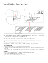
How to Hang Your Ceiling Fan
1. Securely attach the hanger bracket to the ceiling joist
or structural member using the 5” lag bolt. The lag bolt
will pass through the outlet box and into the supporting
member (Fig. 4). You will rst drill a 1/4” pilot hole into the
supporting member to prevent splitting or cracking.
2. Make sure the electrical supply wires, including the
hanger bracket grounding wire are pulled through be-
tween the hanger bracket and the junction box so that
electrical connections can be made later.
3. Carefully place the ceiling canopy over the extension
pole so that it may be attached after hanging and wiring
the fan.
4. Carefully lift the double motor assembly and extension
pole and place the extension pole into the hanger bracket
and secure with the 5/16” x 2-1/2” hanger bracket bolt
and locking hex nut provided (Figure 5).
The hanger bracket must be securely anchored to a struc-
tural member and be capable of withstanding a load of
at least 100 lbs.The fan must be hung with at least 7’ of
clearance from oor to blades (Figure 3)
WARNING
Do not connect fan blades until the fan is completely in-
stalled. Hanging fan with blades connected may result in
damage to the fan blades.
WARNING
To avoid possible shock, do not pinch wires between the
extension pole and the hanger bracket.
WARNING
Figure 5
Figure 4
Figure 3
Junction Box
Ceiling Joist
Hanger Bracket
Wood Member
(2” x 4” Approx.)
Floor
Ceiling
No
less than
7 ft
INSTALLATION NOTE
Prior to hanging the fan, determine which direction the
fan will hang. The fan may hang parallel or perpendicular
to the hanger bracket. The hanger bracket also may be
rotated 360 degrees on the outlet box.
If you are installing your ceiling fan on a sloped ceiling,
the hanger bracket must be mounted with the opening
parallel to the slope.
Ceiling
Ceiling
Hanger Bracket Bolt
Extension Pole
Hanger Bracket
Lock Nut

6
Electrical Requirements
Wiring and Control Options
Please choose one of the following options and proceed
to the page as indicated.
1. Standard 4-position, 2-speed, fan-only C3 wall control,
see page 8.
2. Optional fan & light slide wall control (C6). Please see
instructions provided with control.
NOTE: If you are using a Fanimation Light Fixture with your fan, see Ceiling Fan Light Kit Installation Instructions (packed
with light kit) for wiring.
DAMP LOCATION CEILING FAN: If you have purchased
a Damp Location Ceiling Fan, you may only use light kits
marked suitable for use in damp locations.
To reduce the risk of re, electrical shock, or personal
injury, mount fan to outlet box marked acceptable for fan
support, and use screws supplied with outlet box. Most
outlet boxes commonly used for support of light xtures
are not acceptable for fan support and may need to be
replaced. Consult a qualied electrician if in doubt.
WARNING
Turning off wall switch is not sufcent. To avoid pos-
sible electrical shock, be sure electricity is turned off at
the main fuse box before wiring. All wiring must be in
accordance with National and Local codes and the ceiling
fan must be properly grounded as a precaution against
possible electrical shock.
WARNING
To avoid re or shock, follow all wiring instructions
carefully. Any electrical work not described in these
instructions should be done or approved by a licensed
electrician.
WARNING
Your new ceiling fan will require a grounded electrical sup-
ply line of 120 volts AC, 60 Hz, 15 amp circuit. The outlet
box must be securely anchored and capable of withstand-
ing a load of at least 100 lbs.
f your fan is to replace an existing light xture, turn elec-
tricity off at the main fuse box at this time and remove the
existing light xture.

7
How to Wire Your Ceiling Fan
To avoid possible electrical shock, be sure electricity
is turned off at the main fuse box before wiring. Note: If
you are not sure if the outlet box is grounded, contact a
licensed electrician for advice, as it must be grounded for
safe operation.
WARNING
Check to see that all connections are tight, including
ground, and that no bare wire is visible at the wire
connectors, except for the ground wire. Do not operate
fan until the blades is in place. Noise and fan damage
could result.
WARNING
If you feel that you do not have enough electrical wiring
knowledge or experience, have your fan installed by a
licensed electrician.
If separate control of light xture (optional) is desired, a
separate switch leg from the outlet box is required. In this
instance the blue wire from the fan will be connected to
the light switch leg (typically red wire)
INSTALLATION NOTE
1. Run the blue, black and white fan wires through the
wiring hole in the side of the hanger bracket to allow for
electrical connections.
2. Connect the green grounding wire from the hanger
bracket to the grounding wire from the outlet box (this may
be a bare wire or a wire with green insulation). Securely
connect these two wires with wire connectors supplied
with your fan.
3. Securely connect the white wire from the fan motor
to the white supply (neutral) wire using wire connector
supplied (Fig. 5). Securely connect the black fan motor
wire and blue wire to the black supply wire using wire
connector supplied (Fig. 6).
NOTE: If you are using a Fanimation Light Fixture with
your fan, see Ceiling Fan Light Kit Installation Instructions
for wiring.
4. After connections have been made, turn leads upward
and carefully push leads into the outlet box, with the white
and green leads to one side of the box and the black and
blue leads towards the other side.
5. After all electrical connections are made, secure the
ceiling canopy to the hanger bracket with the screws
provided (screws are packed already attached to the
hanger bracket).
6. Prior to attaching blades, check to see that all
connections are tight, including switch caps located on
ends of motors and below the connecting harness.
120 VAC Supply
(User Supplied)
Junction Box
Black Wire (Hot)
White
(Neutral)
Figure 6
Blue Wire (Light Fixture)
Green Wire (Ground)
(To/From mounting
bracket)

8
How to Wire Your Ceiling Fan - C3 Wall Control
Operating Instructions - C3 Wall Control
To avoid possible re or shock, make sure that the elec-
trical wires are completely inside the outlet box and not
pinched between the wall plate and the wall.
WARNING
If you feel that you do not have enough electrical wir-
ing knowledge or experience, have your fan installed
by a licensed electrician.
NOTE: If fan or supply wires are different colors than indi-
cated, have this unit installed by a qualied electrician.
Check to see that all connections are tight, including
ground, and that no bare wire is visible at the wire con-
nectors, except for the ground wire. Do not operate fan
until the blades is in place. Noise and fan damage could
result.
WARNING
Figure 8
Figure 9
1. Operating & Using Wall Control (Figure 9):
2. Check the operation of the fan by moving the slide
switch on the wall control to low and then to high.
• OFF Switch – fan off
• LO Slide Switch – low fan speed
• HI Slide Switch – hi fan speed
• OFF Switch – fan off
1. Complete steps 1 thru 6 “How to Wire Your Ceiling
Fan” from page 7.
2. Installing Wall Control (Figures 7 & 8):
• With electrical power still disconnected, remove the
existing wall plate and switch.
• Make wiring connections with wire nuts as shown in
Figure 7.
– One black wire from wall control unit to black
(hot supply).
– One black wire from wall control unit to black wire
leading to ceiling outlet box.
• Attach wall control unit to outlet box using the two
6-32 screws provided.
• Attach wall plate to the switch control front using the
two small screws provided.
• Restore electrical power.
BLK
TO HOT
GRN from bracket
120 VAC Supply
(User Supplied)
WH-TO MOTOR
BLK-TO MOTOR
BLUE-Not Used
BLK
TO FAN
BLK
WH
GRN
Figure 7
NOTE: Supply wires and fan wires
omitted for clarity.
O
F
F
O
F
F
H
I
L
O
3
5
⁄16 in.
OFF
OFF
HI
LO

9
Mounting the Fan Blades
Maintenance
1. Blade holders come packed in two different bundles,
one set has blades marked with a red dot (4 pcs.) and
one set has blades marked with white dot (4 pcs.). These
colored dots indicate which motor to attach those blade
holders to.
2. Using the 10-32 x 1/2” machine screws attach the blade
holders to the corresponding rubber flywheel which also
will be marked with a white or a red dot.
NOTE: When attaching blade holders to the rubber
flywheel use the threaded holes marked with the number 4
(#4 holes are also marked with the square outline).
3. Make sure the screws securing the blade holders to the
flywheel are tight and that the blade holders are properly
seated on the flywheel (Figure 11).
Figure 11
Blade Attachment
Blade Cleaning
Do not connect fan blades until the fan is completely
installed. Installing the fan with blades assembled may
result in damage to the fan blades.
INSTALLATION NOTE
Attach the fan blades after hanging the fan body and
wiring the fan to prevent blade breakage or damage.
INSTALLATION NOTE
Periodic light dusting of the Palm Leaf and Woven Bamboo
blades is recommended. A feather duster will work best.
Avoid using water, cleansers, or harsh rags, which can
warp and tear the blades.
Do not use water when cleaning your ceiling fan. It
could damage the motors or the blades and create the
possibility of electrical shock.
INSTALLATION NOTE
Periodic cleaning of your new ceiling fan is the only main-
tenance that is needed.
When cleaning, use only a soft brush or lint free cloth to
avoid scratching the nish.
Abrasive cleaning agents are not required and should be
avoided to prevent damage to nish.
Blade pitch is very important in the operation of your
fan. Use blade holders and blade sets designed for the
Palisade fan only.
INSTALLATION NOTE
Flywheel
Blade Holder
Screw
(2 per blade holder)
Figure 10
Side A
Fan Blade
Side B
You will nd the fan blade set packed in its own carton and the blade holders and hardware bag in the small hardware box
in the fan box (FP220). The hardware bag for the blade holders consists of 16 screws and a Phillips head screwdriver.
1. Lay side “A” of the blade holder on a flat surface with the
inside of the blade holder facing up. This is the side with
the threaded posts and pitched foot.
2. Position the palm leaf, or the woven bamboo blade over
the blade holder with the threaded posts showing. Make
sure the bottom edge of the blade is fully seated against
the blade holder.
3. Place side “B” of the blade holder on top of the blade,
positioning the holes over the threaded posts.
4. With a Philips screwdriver, thread both screws into the
posts but do not fully tighten.
5. Prior to final tightening, position the centerline of the
blade holder with the center of the end of the blade.
6. Tighten both screws to secure the blade. (Figure 10)
NOTE: Use screws provided in the blade mounting hard-
ware bag only. (This bag includes the blue Fanimation
screwdriver.)

10
Mounting the Multi-Colored Parrot (Optional)
Do not hang the perch with the parrot while fan is
operating. Personal injury may result and/or damage to
the fan blades.
INSTALLATION NOTE
1. Hang the perch so that it is centered under the
connecting harness.
2. Position the parrot on the perch support as shown
(Figure 12).
Connecting
Harness
Perch
Parrot
Perch Support
Mounting the Filligree (Optional)
Figure 12
You will nd the parrot and the perch in its own package
(P38).
Figure 13
Horizontal Tube
Foam Pad (Typical)
Connecting
Harness
Bolt (2)
Foot with
Foam Pad
Locknut
(2)
Filligree (2)
Screw (4)
Foam Pad
(Typical)
Foam Pad
(6 places)
Do not fasten the ligree while fan is operating. Personal
injury may result and/or damage to the fan blades.
INSTALLATION NOTE
1. Attach foam pads as shown (Figure 13).
NOTE: Pads may already be attached.
2. Insert two screws through the mounting bracket holes in
the lligree pieces and secure to the extension pole.
Do not over tighten the screws.
3. Repeat this process for the bottom holes (Figure 13).
NOTE: The foot of the ligree rests on the top of the
horizontal tube.
You will nd the lligree and the hardware in its own
package (FL_ _).
If one of the filigree feet does not touch the horizontal
tube. Loosen the connecting harness bolts and locknuts,
and adjust the horizontal tube so that both filligree feet
touch the tube.
INSTALLATION NOTE

11
Trouble Shooting
WARNING
For your own safety turn off power at fuse box or circuit breaker before trouble shooting your fan.
Trouble Probable Cause Suggested Remedy
1. FAN WILL NOT START
1. Fuse or circuit breaker blown.
2. Loose power line connections to the fan, or loose
switch wire connections in the switch housing.
1. Check main and branch circuit fuses or circuit break-
ers.
2. Check line wire connections to fan and switch wire
connections in the switch housings.
CAUTION: Make sure main power is turned off !
2. FAN SOUNDS NOISY
1. Blades not attached to fan.
2. Loose screws in motor housing.
3. Screws securing fan blade holders to motor flywheel
are loose.
4. Wire connectors inside housing rattling.
5. Motor noise caused by solid state variable speed
control.
6. Screws holding blades to blade holders are loose.
7. Rubber flywheel set screw loose.
1. Attach blades to fan before operating.
2. Check to make sure all screws in motor housing are
snug (not over-tight).
3. Check to make sure the screws which attach the fan
blade holders to the motor flywheel are tight.
4. Check to make sure wire connectors in switch
housing are not rattling against each other or against the
interior wall of the switch housing.
CAUTION: Make sure main power is turned off !
5. Some fan motors are sensitive to signals from solid-
state variable speed controls. Solid-state controls are
not recommended, choose an alternative control method.
6. Tighten screws securely.
7. Tighten set screw securely.
3. FAN WOBBLES
EXCESSIVELY
1. Hanger bracket bolt holding the extension pole is
loose.
2. Bolts holding the connecting harness to the extension
pole are loose.
3. Screws securing fan blade holders to flywheel are
loose.
4. Blade holders not seated properly.
5. Hanger bracket is not rigidly secured to a structural
member.
6. Fan blades out of balance.
1. Tighten hanger bracket bolt.
2. Tighten bolts holding connecting harness to the
extension pole.
3. Check to be sure screws which attach the fan blade
holders to the flywheel are tight.
4. Check to be sure the fan blade holders seat firmly and
uniformly to the surface of the flywheel. If holders are
seated incorrectly, loosen the screws and retighten.
5. Check to see that the hanger bracket is secured to
a structural member with the 5” lag bolt. The hanger
bracket must be securely anchored and should not have
any movement.
6. Interchanging an adjacent blade pair can redistribute
the weight and result in a smoother operation. A heavy
blade can also be identified by turning off the fan and
seeing if one blade on one or both sides quickly drops to
the down position. Trade out this blade with an adjacent
blade or one of the complementary blades shipped in the
blade set box.

12
Before discarding packaging materials, be certain all parts have been removed
How to Order Parts
When ordering repair parts, always
give the following information:
• Part Number
• Part Description
• Ceiling Fan Model Number
Contact your retail store for repair parts.
Parts List
Ref. No. Description Part #
1 Hanger Bracket
P822ÜÜ
2 Ceiling Canopy
3 Ceiling Canopy Screws (2)
4 Double Fan Motor Assembly
FP220ÜÜ
Blade Holder Pack Containing (Eight-2 Pc):
5 Red (Four-2 pc holders)
P40DCBHÜÜ
White (Four-2 pc holders)
6 Extension Pole (purchased seperately)
EPÜ-ÜÜ
Hardware Bag Containing:
HDWFP220ÜÜ
7 2˝ x
5
⁄16˝–18 Hanger Bracket Bolt
8
5
⁄16˝–18 Nylon Lock Nut
9
3
⁄8˝ x 5˝ Lag Bolt
10
3
⁄8˝ Washer
11 Flywheel Screws (16)
12 ˝–20 x 2˝ Connecting Harness Bolt (2)
13 ˝–20 Nylon Lock Nut, Black (2)
14 Wire Connectors (3)
Blade Mounting Hardware Bag Containing:
BMH220ÜÜ
15
3
⁄16˝–24 x
3
⁄8˝ Phillips Screws (16 pc)
16 Phillips Screwdriver
Ü
Include Length
ÜÜ
Insert FINISH CODES (Refer to fan model number located on fan motor assembly)
Model #FP220

13
NOTE: The illustration shown is not to scale or its actual conguration may vary, wires omitted for clarity.
Exploded-View
Side B
Side A
5 (Ref)
9
8
10
11
12
13
14
15
16
7
6
4
5
3
2
1
The Palisade
®
FP220
Figure 14

Copyright 2004 Fanimation 2004/02
10983 Bennett Parkway
Zionsville, IN 46077
(888) 567-2055
FAX (866) 482-5215
Outside U.S. call (317) 733-4113
Visit Our Website @ www.fanimation.com
/