ESAB Caddy Arc 151i User manual

Category
Welding System
Type
User manual

This manual is also suitable for

GB
Valid for serial no. 803-xxx-xxxx0460 446 001 GB 091020
Caddy
Arc 151i, Arc 201i
Instruction manual
- 2 -
TOCe
Rights reserved to alter specifications without notice.
1 DIRECTIVE 3. . . . . . . . . . . . . . . . . . . . . . . . . . . . . . . . . . . . . . . . . . . . . . . . . . . . . . . .
2 SAFETY 3. . . . . . . . . . . . . . . . . . . . . . . . . . . . . . . . . . . . . . . . . . . . . . . . . . . . . . . . . . .
3 INTRODUCTION 4. . . . . . . . . . . . . . . . . . . . . . . . . . . . . . . . . . . . . . . . . . . . . . . . . . .
3.1 Equipment 4. . . . . . . . . . . . . . . . . . . . . . . . . . . . . . . . . . . . . . . . . . . . . . . . . . . . . . . . . . . . . . . .
3.2 Control panel 5. . . . . . . . . . . . . . . . . . . . . . . . . . . . . . . . . . . . . . . . . . . . . . . . . . . . . . . . . . . . .
4 TECHNICAL DATA 6. . . . . . . . . . . . . . . . . . . . . . . . . . . . . . . . . . . . . . . . . . . . . . . . .
5 INSTALLATION 7. . . . . . . . . . . . . . . . . . . . . . . . . . . . . . . . . . . . . . . . . . . . . . . . . . . .
5.1 Location 7. . . . . . . . . . . . . . . . . . . . . . . . . . . . . . . . . . . . . . . . . . . . . . . . . . . . . . . . . . . . . . . . . .
5.2 Mains power supply 7. . . . . . . . . . . . . . . . . . . . . . . . . . . . . . . . . . . . . . . . . . . . . . . . . . . . . . . .
5.2.1 Recommended fuse sizes and minimum cable area 7. . . . . . . . . . . . . . . . . . . . . . .
6 OPERATION 8. . . . . . . . . . . . . . . . . . . . . . . . . . . . . . . . . . . . . . . . . . . . . . . . . . . . . . .
6.1 PFC - Power factor correction 8. . . . . . . . . . . . . . . . . . . . . . . . . . . . . . . . . . . . . . . . . . . . . . .
6.2 Connections and control devices 8. . . . . . . . . . . . . . . . . . . . . . . . . . . . . . . . . . . . . . . . . . . .
6.3 Connection of welding and return cable 8. . . . . . . . . . . . . . . . . . . . . . . . . . . . . . . . . . . . . . .
6.4 Overheating protection 9. . . . . . . . . . . . . . . . . . . . . . . . . . . . . . . . . . . . . . . . . . . . . . . . . . . . .
6.5 MMA welding 9. . . . . . . . . . . . . . . . . . . . . . . . . . . . . . . . . . . . . . . . . . . . . . . . . . . . . . . . . . . . .
6.6 TIG welding 9. . . . . . . . . . . . . . . . . . . . . . . . . . . . . . . . . . . . . . . . . . . . . . . . . . . . . . . . . . . . . . .
6.7 Remote control unit 10. . . . . . . . . . . . . . . . . . . . . . . . . . . . . . . . . . . . . . . . . . . . . . . . . . . . . . . .
7 MAINTENANCE 10. . . . . . . . . . . . . . . . . . . . . . . . . . . . . . . . . . . . . . . . . . . . . . . . . . . .
7.1 Inspection and cleaning 11. . . . . . . . . . . . . . . . . . . . . . . . . . . . . . . . . . . . . . . . . . . . . . . . . . . .
8 FAULT-TRACING 11. . . . . . . . . . . . . . . . . . . . . . . . . . . . . . . . . . . . . . . . . . . . . . . . . .
8.1 Fault codes 11. . . . . . . . . . . . . . . . . . . . . . . . . . . . . . . . . . . . . . . . . . . . . . . . . . . . . . . . . . . . . . .
9 ORDERING SPARE PARTS 12. . . . . . . . . . . . . . . . . . . . . . . . . . . . . . . . . . . . . . . . .
10 DISMANTLING AND SCRAPPING 12. . . . . . . . . . . . . . . . . . . . . . . . . . . . . . . . . . .
DIAGRAM 14. . . . . . . . . . . . . . . . . . . . . . . . . . . . . . . . . . . . . . . . . . . . . . . . . . . . . . . . . . . .
ORDERING NUMBER 18. . . . . . . . . . . . . . . . . . . . . . . . . . . . . . . . . . . . . . . . . . . . . . . . .
ACCESSORIES 19. . . . . . . . . . . . . . . . . . . . . . . . . . . . . . . . . . . . . . . . . . . . . . . . . . . . . . .
- 3 -
bh32d1e
1 DIRECTIVE
DECLARATION OF CONFORMITY
ESAB AB, Welding Equipment, SE-695 81 Laxå, Sweden, gives its unreserved guarantee that weld
ing power source Arc 151i, Arc 201i from serial number 803 are constructed and tested in compliance
with the standard EN 60974-1 and EN 60974-10 (Class A) in accordance with the requirements of
directive (2006/95/EC) and (2004/108/EEC).
--------------------------------------------------------------------------------------------------------------
Kent Eimbrodt
Global Director
Equipment and Automation
Laxå 2008-01-25
2 SAFETY
Users of ESAB welding equipment have the ultimate responsibility for ensuring that anyone who works on or near the equipment
observes all the relevant safety precautions. Safety precautions must meet the requirements that apply to this type of welding
equipment. The following recommendations should be observed in addition to the standard regulations that apply to the work
place.
All work must be carried out by trained personnel well-acquainted with the operation of the welding equipment. Incorrect oper
ation of the equipment may lead to hazardous situations which can result in injury to the operator and damage to the equipment.
1. Anyone who uses the welding equipment must be familiar with:
its operation
location of emergency stops
its function
relevant safety precautions
welding
2. The operator must ensure that:
no unauthorized person is stationed within the working area of the equipment when it is started up.
no-one is unprotected when the arc is struck
3. The workplace must:
be suitable for the purpose
be free from drafts
4. Personal safety equipment
Always wear recommended personal safety equipment, such as safety glasses, flame-proof clothing, safety gloves.
Note! Do not use safety gloves when replacing wire.
Do not wear loose-fitting items, such as scarves, bracelets, rings, etc., which could become trapped or cause burns.
5. General precautions
Make sure the return cable is connected securely.
Work on high voltage equipment may only be carried out by a qualified electrician.
Appropriate fire extinquishing equipment must be clearly marked and close at hand.
CAUTION!
This product is solely intended for arc welding.
WARNING!
Do not use the power source for thawing frozen pipes.
GB
- 4 -
bh32d1e
WARNING
Read and understand the instruction manual before installing or operating.
Arc welding and cutting can be injurious to yourself and others. Take precausions when welding.
Ask for your employer's safety practices which should be based on manufacturers' hazard data.
ELECTRIC SHOCK - Can kill
Install and earth the welding unit in accordance with applicable standards.
Do not touch live electrical parts or electrodes with bare skin, wet gloves or wet clothing.
Insulate yourself from earth and the workpiece.
Ensure your working stance is safe.
FUMES AND GASES - Can be dangerous to health
Keep your head out of the fumes.
Use ventilation, extraction at the arc, or both, to take fumes and gases away from your breathing zone
and the general area.
ARC RAYS - Can injure eyes and burn skin.
Protect your eyes and body. Use the correct welding screen and filter lens and wear protective
clothing.
Protect bystanders with suitable screens or curtains.
FIRE HAZARD
Sparks (spatter) can cause fire. Make sure therefore that there are no inflammable materials nearby.
NOISE - Excessive noise can damage hearing
Protect your ears. Use earmuffs or other hearing protection.
Warn bystanders of the risk.
MALFUNCTION - Call for expert assistance in the event of malfunction.
PROTECT YOURSELF AND OTHERS!
CAUTION!
Read and understand the instruction manual before
installing or operating.
CAUTION!
Class A equipment is not intended for use in residential locations where
the electrical power is provided by the public low-voltage supply system.
There may be potential difficulties in ensuring electromagnetic
compatibility of class A equipment in those locations, due to conducted
as well as radiated disturbances.
ESAB can provide you with all necessary welding protection and accessories.
3 INTRODUCTION
Arc 151i, Arc 201iis a welding current power source intended for use with coated
electrodes (MMA welding) and TIG welding.
ESAB's accessories for the product can be found on page 19.
3.1 Equipment
GB
- 5 -
bh32d1e
Arc 151i, Arc 201i is supplied with a 3 m welding cable, return cable, 3 m mains
cable and an instruction manual for power source and control panel.
Instruction manuals in other languages can be downloaded from the website,
www.esab.com.
3.2 Control panel
Control panel A31
Knob for setting the current
Mains voltage LED (green)
Thermal overload trip indicator
(yellow)
Control panel A33
Welding process parameters are controlled via the control panel.
NOTE! See the separate instruction manual for a detailed description of the control
panel.
GB
- 6 -
bh32d1e
4 TECHNICAL DATA
Arc 151i Arc 201i
Mains voltage 230 V, 1 50/60 Hz 230 V, 1 50/60 Hz
Primary current
I
max
TIG
I
max
MMA
13.8 A
21.3 A
24.1 A
24.9 A
Mains supply Z
max
0.35 ohm Z
max
0.30 ohm
No-load power 30 W 30 W
Voltage/current range, MMA
A31
8 A /20 V - 150 A /26 V -
A33 4 A /20 V - 150 A /26 V 4 A /20 V - 170 A /26.8 V
Voltage/current range TIG 3 - 150 A 3 - 220 A
Permissible load at MMA
25% duty cycle
60% duty cycle
100% duty cycle
150 A / 26.0 V
100 A / 24.0 V
90 A / 23.6 V
170 A / 26.8 V
130 A / 25.2 V
110 A / 24.4 V
Permissible load at TIG
20% duty cycle
25% duty cycle
60% duty cycle
100% duty cycle
-
150 A / 16.0 V
120 A / 14.8 V
110 A / 14.4 V
220 A / 18.8 V
-
150 A / 16.0 V
110 A / 14.4 V
Power factor at maximum current 0.99 0.99
Efficiency at maximum current 80% 81%
Open-circuit voltage
A31
A33
58 - 72 V
72 V
-
72 V
Operating temperature -10° C - +40° C -10° C - +40° C
Transportation temperature -20° C - +55° C -20° C - +55° C
Constant A-weighted sound pressure < 70 dB < 70 dB
Dimensions, l x b x h 418 x 188 x 208 mm 418 x 188 x 208 mm
Weight
with A31
with A33
7.9 kg
8.1 kg
-
8.3 kg
Enclosure class IP 23 IP 23
Application class
Mains supply, Z
max
Maximum permissible line impedance of the network in accordance with IEC 61000-3-11.
Duty cycle
The duty cycle refers to the time as a percentage of a ten-minute period that you can weld at a cer
tain load without overloading. The duty cycle is valid for 40° C.
Enclosure class
The IP code indicates the enclosure class, i. e. the degree of protection against penetration by solid
objects or water. Equipment marked IP23 is designed for indoor and outdoor use.
Application class
The symbol indicates that the power source is designed for use in areas with increased
electrical hazard.
GB
- 7 -
bh32d1e
5 INSTALLATION
The installation must be executed by a professional.
Note!
Mains supply requirements
High power equipment may, due to the primary current drawn from the mains supply, influence the
power quality of the grid. Therefore connection restrictions or requirements regarding the
maximum permissible mains impedance or the required minimum supply capacity at the interface
point to the public grid may apply for some types of equipment (see technical data). In this case it
is the responsibility of the installer or user of the equipment to ensure, by consultation with the
distrubution network operator if necessary, that the equipment may be connected.
5.1 Location
Position the power source such that its cooling air inlets and outlets are not
obstructed.
5.2 Mains power supply
Check that the welding power source is connected
to the correct voltage and that the correct fuse size
is used. A protective earth connection must be
made in accordance with regulations
Location of rating plate
5.2.1 Recommended fuse sizes and minimum cable area
Arc 151i Arc 201i
Mains voltage 230 V 10 %, 1-phase 230 V 10 %, 1-phase
Mains frequency 50-60 Hz 50-60 Hz
Mains cable, area 3G2.5 mm
2
3G2.5 mm
2
Phase current I
1eff
11.5 A 13.4 A
Welding cable, area 16 mm
2
16 mm
2
Fuse
anti-surge
type C MCB
16 A
13 A
16 A
16 A
NOTE!
The cable area and fuse rating above comply with Swedish regulations. Use the
welding power source in accordance with the relevant national regulations.
GB
- 8 -
bh32d1e
6 OPERATION
General safety regulations for the handling of the equipment can be found on
page 3. Read through before you start using the equipment!
6.1 PFC - Power factor correction
The Caddy Arc 151i/201i are 230 V single-phase power sources equipped with a
PFC circuit making it possible to use the full range of the machine on a 16 A fuse.
The PFC also protects the machines against fluctuating mains voltage and makes it
safer to use with a generator. Caddy Arc 151i/201i can operate with extra long
mains cables, over 100 m, giving you a very larger working radius.
6.2 Connections and control devices
1 Connection (+)
MMA: for return cable or welding cable
TIG: for return cable
4 Connection (+)
MMA: for return cable or welding cable
TIG: for Tig torch l
2 Connection for remote control unit 5 Toggle switch for mains power supply 0 / 1
3 Control panel, see under 3.2 6 Mains cable
6.3 Connection of welding and return cable
The power source has two outputs, a positive terminal (+) and a negative terminal
(-), for connecting welding and return cables. The output to which the welding cable
GB
cmha2p11
cmha2p10
- 9 -
bh32d1e
is connected depends on the type of electrode used. The connecting polarity is
stated on the electrode packaging. Connect the welding cable to the terminal stated
on the electrode packaging.
Connect the return cable to the other output on the power source. Secure the return
cable's contact clamp to the work piece and ensure that there is good contact
between the work piece and the output for the return cable on the power source.
6.4 Overheating protection
The welding power source has a thermal overload trip which operates if the
temperature becomes too high, interrupting the welding current and lighting a yellow
indicating lamp on the front of the power source. The thermal overload trip resets
automatically when the temperature has fallen.
6.5 MMA welding
Arc 151i / 201i gives direct current, and you can weld most metals to alloy and non-
alloy steel, stainless steel and cast iron.
Arc 151i / 201i allows you to weld most coated electrodes from Ø 1.6 to Ø 3.25.
MMA welding may also be referred to as welding with coated electrodes. Striking the arc
melts the electrode, and its coating forms protective slag.
If, when striking the arc, the tip of the electrode is pressed against the metal, it immedi
ately melts and sticks to the metal, rendering continued welding impossible.
Therefore, the arc has to be struck in the same way that you would light a match.
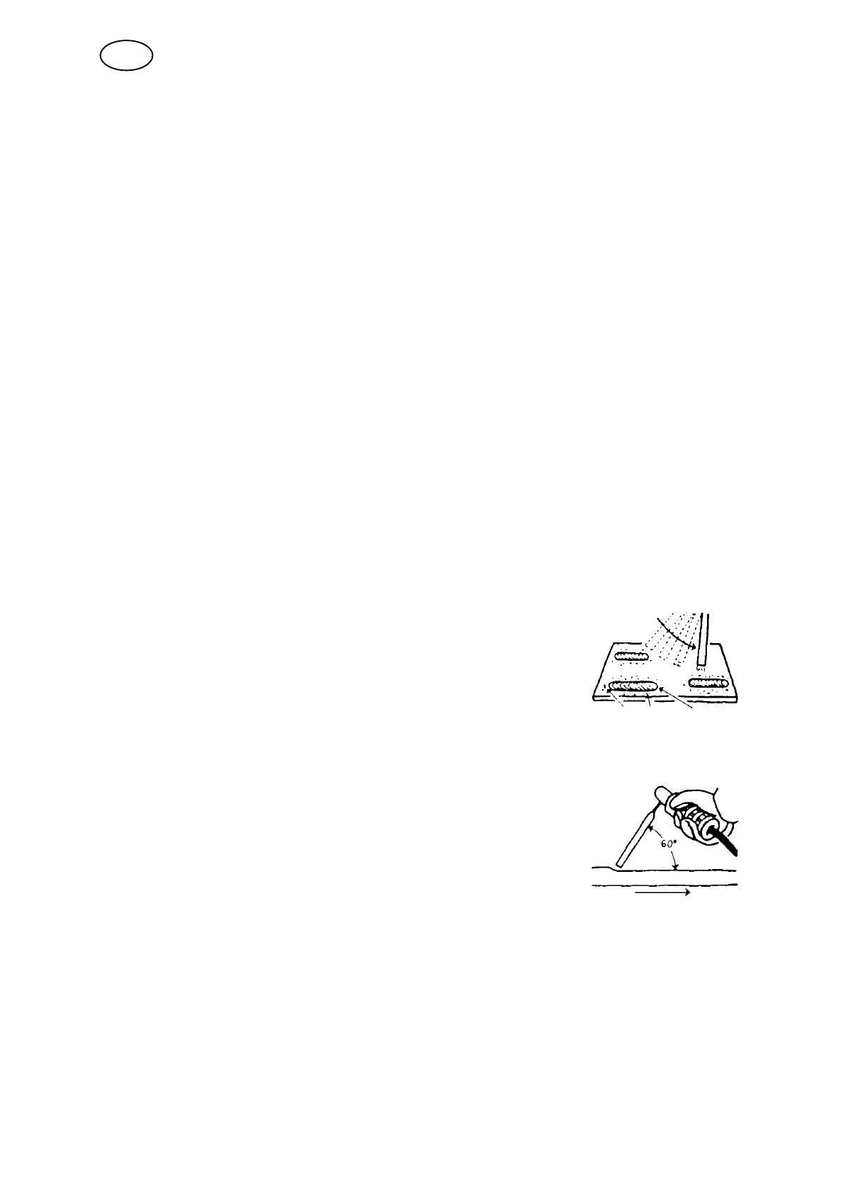
Quickly strike the electrode against the metal, then raise it so
as to give an appropriate arc length (approx. 2 mm). If the arc
is too long, it will crackle and spit before finally going out com
pletely.
If you are working on a welding bench, check before attempting
to strike the arc that residual waste metal, pieces of electrode
or other objects on the bench do not insulate the part to be
welded.
Once the arc has been struck, move the electrode from left to
right. The electrode must be at an angle of 60° to the metal in
relation to the direction of welding.
When you want to weld wide beads, or when you want the weld
to be so thick that you have to weld in a number of layers, how
ever, you have to use lateral movements.
6.6 TIG welding
TIG welding melts the metal of the workpiece, using an arc struck from a tungsten
electrode, which does not itself melt. The weld pool and the electrode are protected
by shielding gas.
TIG welding is particularly useful where high quality is demanded and for welding
thin plate. Arc 151i / 201i also has good characteristics for TIG welding.
GB
- 10 -
bh32d1e
In order to TIG weld Arc 151i / 201i must be equipped with:
a TIG torch with gas valve
a welding gas cylinder (a suitable welding gas)
a welding gas regulator (suitable gas regulator)
tungsten electrode
suitable auxiliary material, if necessary.
TIG scrape start (only A31)
To scrape start lightly scrape the tungsten
electrode against the workpiece to create an
arc.
”Live TIG-start” (only A33)
With “Live TIG start” the arc strikes when the tungsten electrode is brought into
contact with the workpiece and then lifted away from it.
6.7 Remote control unit
The remote control unit is connected to the remote control socket on the power
source.
7 MAINTENANCE
Regular maintenance is important for safe, reliable operation.
Only those persons who have appropriate electrical knowledge (authorized
personnel) may remove the safety plates to connect or carry out service,
maintenance or repair work on welding equipment.
CAUTION!
All guarantee undertakings from the supplier cease to apply if the customer himself
attempts any work in the product during the guarantee period in order to rectify any faults.
GB
- 11 -
bh32d1e
7.1 Inspection and cleaning
Power source
Check regularly that the welding power source is not clogged with dirt.
How often and which cleaning methods apply depend on: the welding process, arc
times, placement, and the surrounding environment. It is normally sufficient to blow
down the power source with dry compressed air (reduced pressure) once a year.
Clogged or blocked air inlets and outlets otherwise result in overheating.
TIG torch
The TIG torch's wear parts should be cleaned and replaced at regular intervals in
order to achieve trouble-free welding.
8 FAULT-TRACING
Try these recommended checks and inspections before sending for an authorized
service technician.
Type of fault Corrective action
No arc.
Check that the mains power supply switch is
turned on.
Check that the welding current supply and return
cables are correctly connected.
Check that the correct current value is set.
Check to see whether the MCB has tripped.
The welding current is interrup
ted during welding.
Check whether the thermal cut-outs have tripped
(indicated by the orange lamp on the front panel).
Check the mains power supply fuses.
The thermal cut-out trips fre
quently.
Check to see whether the dust filter is clogged.
Make sure that you are not exceeding the rated
data for the power source (i.e. that the unit is not
being overloaded).
Poor welding performance.
Check that the welding current supply and return
cables are correctly connected.
Check that the correct current value is set.
Check that the correct electrodes are being used.
Check the gas flow.
8.1 Fault codes
Arc 151i, 201i comes with built-in fault monitoring. If a fault occurs, a code is shown
in the display. See instruction manual for the control panel.
GB
- 12 -
bh32d1e
9 ORDERING SPARE PARTS
Repair and electrical work should be performed by an authorized ESAB serviceman.
Use only ESAB original spare and wear parts.
Arc 151i, Arc 201i is designed and tested in accordance with the international and Eu
ropean standards 60974-1 and 60984-10 . It is the obligation of the service unit which
has carried out the service or repair work to make sure that the product still conforms
to the said standard.
Spare parts may be ordered through your nearest ESAB dealer, see the last page of
this publication.
10 DISMANTLING AND SCRAPPING
Welding equipment primarily consists of steel, plastic and non-ferrous metals, and must
be handled according to local environmental regulations.
Coolant must also be handled according to local environmental regulations.
Do not dispose of electrical equipment together with normal waste!
In observance of European Directive 2002/96/EC on Waste Electrical and Electronic
Equipment and its implementation in accordance with national law, electrical equipment
that has reached the end of its life must be collected separately and returned to an
environmentally compatible recycling facility. As the owner of the equipment, you should
get information on approved collection systems from our local representative.
By applying this European Directive you will improve the environment and human
health!
GB
- 13 -
p1
NOTES
___________________________________________________________________
___________________________________________________________________
___________________________________________________________________
___________________________________________________________________
___________________________________________________________________
___________________________________________________________________
___________________________________________________________________
___________________________________________________________________
___________________________________________________________________
___________________________________________________________________
___________________________________________________________________
___________________________________________________________________
___________________________________________________________________
___________________________________________________________________
___________________________________________________________________
___________________________________________________________________
___________________________________________________________________
___________________________________________________________________
___________________________________________________________________
___________________________________________________________________
Diagram
- 14 -
bh32e
Arc 151i
- 15 -
bh32e
- 16 -
bh32e
Arc 201i
- 17 -
bh32e
Arc 151i/Arc 201i
Edition 091020
Ordering number
- 18 -
bh32o
Ordering no. Denomination Type
0460 445 881 Welding Power source Caddy Arc 151i, A31
0460 445 883 Welding Power source Caddy Arc 151i, A33
0460 445 884 Welding Power source Caddy Arc 201i, A33
0460 449 074 Instruction manual Control
panel
Caddy A32, A33, A33
0459 839 027 Spare parts list Caddy Arc 151i, Arc 152i, A31
0459 839 028 Spare parts list Caddy Arc 151i, Arc 201i, A33
Instruction manuals and the spare parts list are available on the Internet at www.esab.com
R0460 446/E091020/P24
Arc 151i/Arc 201i
Accessories
- 19 -
bh32a
Strap . . . . . . . . . . . . . . . . . . . . . . . . . . . . . . . . . . . 0460 265 001
Cable holder 2 pcs . . . . . . . . . . . . . . . . . . . . . . 0460 265 002
Shoulder strap . . . . . . . . . . . . . . . . . . . . . . . . . . 0460 265 003
Trolley . . . . . .
for 5-10 litre gasbottle . . . . . . . . . . . . . . . . . . . . . 0459 366 885
Welding cable kit, Arc 151i . . . . . . . . . . . . . .
Return cable kit, Arc 151i . . . . . . . . . . . . . . . .
Welding cable kit, Arc 201i . . . . . . . . . . . . . . .
Return cable kit, Arc 201i . . . . . . . . . . . . . . . .
0700 006 898
0700 006 899
0700 006 900
0700 006 901
Tig torch TXH 150V, Arc 151i . . . . . . . . . . . .
Tig torch TXH 200V, Arc 201i . . . . . . . . . . . . .
0460 011 843
0460 012 841
R0460 446/E091020/P24
Arc 151i/Arc 201i
- 20 -
bh32a
Only for A33 control panel
Remote control MMA 1 (10 m cable) . . . . . . .
MMA and TIG: current
0349 501 024
Foot control FS002 . . . . . . . . . . . . . . . . . . . . . .
MMA and TIG current
0349 090 886
Remote control unit AT1 . . . . . . . . . . . . . . . . .
MMA and TIG: current
0459 491 896
Remote control unit AT1 CF . . . . . . . . . . . . .
MMA and TIG: rough and fine setting of
current.
0459 491 897
Remote cable 12 pole - 8 pole
5 m . . . . . . . . . . . . . . . . . . . . . . . . . . . . . . . . . . . . .
10 m . . . . . . . . . . . . . . . . . . . . . . . . . . . . . . . . . . . .
15 m . . . . . . . . . . . . . . . . . . . . . . . . . . . . . . . . . . . .
25 m . . . . . . . . . . . . . . . . . . . . . . . . . . . . . . . . . . . .
0459 552 880
0459 552 881
0459 552 882
0459 552 883
  • Page 1 1
  • Page 2 2
  • Page 3 3
  • Page 4 4
  • Page 5 5
  • Page 6 6
  • Page 7 7
  • Page 8 8
  • Page 9 9
  • Page 10 10
  • Page 11 11
  • Page 12 12
  • Page 13 13
  • Page 14 14
  • Page 15 15
  • Page 16 16
  • Page 17 17
  • Page 18 18
  • Page 19 19
  • Page 20 20
  • Page 21 21
  • Page 22 22
  • Page 23 23
  • Page 24 24

ESAB Caddy Arc 151i User manual

Category
Welding System
Type
User manual
This manual is also suitable for

Ask a question and I''ll find the answer in the document

Finding information in a document is now easier with AI