Baxi 600 System User guide
- Category
- Water heaters & boilers
- Type
- User guide
This manual is also suitable for

Please keep these instructions in a safe place.
If you move house please hand them over to the next occupier.
United Kingdom
en
User Guide
High Efficiency Wall Hung Condensing Gas Boiler
Baxi System
615 - 618 - 624
624 LPG

Dear Customer,
Thank you very much for buying this appliance.
Please read through the manual carefully before using the product, and keep it in a safe place for later reference. In order to
ensure continued safe and efficient operation we recommend that the product is serviced regularly. Our service and customer
service organisation can assist with this.
We hope you enjoy years of problem-free operation with the product.

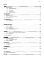
Contents
1 Safety . . . . . . . . . . . . . . . . . . . . . . . . . . . . . . . . . . . . . . . . . . . . . . . . . . . . . . . . . . . . . . . . . . . . . . . . . . . . . . . . . . . . . . . . . . . . 5
1.1 General safety instructions . . . . . .
. . . . . . . . . . . . . . . . . . . . . . . . . . . . . . . . . . . . . . . . . . . . . . . . . . . . . . . . . . . . . . . . . 5
1.2 Recommendations . . . . . . . . . . . . . . . . . . . . . . . . . . . . . . . . . . . . . . . . . . . . . . . . . . . . . . . . . . . . . . . . . . . . . . . . . . . . . 6
1.2.1 The Benchmark Scheme . . . . . . . . . . . . . . . . . . . . . . . . . . . . . . . . . . . . . . . . . . . . . . . . . . . . . . . . . . . . . . . . . 6
1.2.2 Benchmark Commissioning Checklist . . . . . . . . . . . . . . . . . . . . . . . . . . . . . . . . . . . . . . . . . . . . . . . . . . . . . . . 6
1.3 Liabilities . . . . . . . . . . . . . . . . . . . . . . . . . . . . . . . . . . . . . . . . . . . . . . . . . . . . . . . . . . . . . . . . . . . . . . . . . . . . . . . . . . . . . 6
1.3.1 User's liability . . . . . . . . . . . . . . . . . . . . . . . . . . . . . . . . . . . . . . . . . . . . . . . . . . . . . . . . . . . . . . . . . . . . . . . . . .6
1.3.2 Installer's liability . . . . . . . . . . . . . . . . . . . . . . . . . . . . . . . . . . . . . . . . . . . . . . . . . . . . . . . . . . . . . . . . . . . . . . . 7
1.3.3 Manufacturer's liability . . . . . . . . . . . . . . . . . . . . . . . . . . . . . . . . . . . . . . . . . . . . . . . . . . . . . . . . . . . . . . . . . . . 7
2 About this manual . . . . . . . . . . . . . . . . . . . . . . . . . . . . . . . . . . . . . . . . . . . . . . . . . . . . . . . . . . . . . . . . . . . . . . . . . . . . . . . . . . . 8
2.1 General . . . . . . . . . . . . . . . . . . . . . . . . . . . . . . . . . . . . . . . . . . . . . . . . . . . . . . . . . . . . . . . . . . . . . . . . . . . . . . . . . . . . . . 8
2.2 Additional documentation . . . . . . . . . . . . . . . . . . . . . . . . . . . . . . . . . . . . . . . . . . . . . . . . . . . . . . . . . . . . . . . . . . . . . . . . 8
2.3 Symbols used . . . . . . . . . . . . . . . . . . . . . . . . . . . . . . . . . . . . . . . . . . . . . . . . . . . . . . . . . . . . . . . . . . . . . . . . . . . . . . . . . 8
2.3.1 Symbols used in the manual . . . . . . . . . . . . . . . . . . . . . . . . . . . . . . . . . . . . . . . . . . . . . . . . . . . . . . . . . . . . . . 8
2.4 Abbreviations/glossary . . . . . . . . . . . . . . . . . . . . . . . . . . . . . . . . . . . . . . . . . . . . . . . . . . . . . . . . . . . . . . . . . . . . . . . . . . 8
3 Technical specifications . . . . . . . . . . . . . . . . . . . . . . . . . . . . . . . . . . . . . . . . . . . . . . . . . . . . . . . . . . . . . . . . . . . . . . . . . . . . . 10
3.1 Homologations . . . . . . . . . . . . . . . . . . . . . . . . . . . . . . . . . . . . . . . . . . . . . . . . . . . . . . . . . . . . . . . . . . . . . . . . . . . . . . . 10
3.1.1 Certifications . . . . . . . . . . . . . . . . . . . . . . . . . . . . . . . . . . . . . . . . . . . . . . . . . . . . . . . . . . . . . . . . . . . . . . . . . 10
3.2 Technical data . . . . . . . . . . . . . . . . . . . . . . . . . . . . . . . . . . . . . . . . . . . . . . . . . . . . . . . . . . . . . . . . . . . . . . . . . . . . . . . .10
3.2.1 Technical information . . . . . . . . . . . . . . . . . . . . . . . . . . . . . . . . . . . . . . . . . . . . . . . . . . . . . . . . . . . . . . . . . . .10
3.2.2 Dimensions and connections/clearances . . . . . . . . . . . . . . . . . . . . . . . . . . . . . . . . . . . . . . . . . . . . . . . . . . . 11
4 Description of the product . . . . . . . . . . . . . . . . . . . . . . . . . . . . . . . . . . . . . . . . . . . . . . . . . . . . . . . . . . . . . . . . . . . . . . . . . . . . 12
4.1 General description . . . . . . . . . . . . . . . . . . . . . . . . . . . . . . . . . . . . . . . . . . . . . . . . . . . . . . . . . . . . . . . . . . . . . . . . . . . .12
4.2 Operating principle . . . . . . . . . . . . . . . . . . . . . . . . . . . . . . . . . . . . . . . . . . . . . . . . . . . . . . . . . . . . . . . . . . . . . . . . . . . . 12
4.2.1 In operation . . . . . . . . . . . . . . . . . . . . . . . . . . . . . . . . . . . . . . . . . . . . . . . . . . . . . . . . . . . . . . . . . . . . . . . . . . 12
4.3 Control panel description . . . . . . . . . . . . . . . . . . . . . . . . . . . . . . . . . . . . . . . . . . . . . . . . . . . . . . . . . . . . . . . . . . . . . . . 12
4.3.1 Description of the control panel . . . . . . . . . . . . . . . . . . . . . . . . . . . . . . . . . . . . . . . . . . . . . . . . . . . . . . . . . . . 12
4.4 Accessories and options . . . . . . . . . . . . . . . . . . . . . . . . . . . . . . . . . . . . . . . . . . . . . . . . . . . . . . . . . . . . . . . . . . . . . . . . 13
4.4.1 Optional accessories . . . . . . . . . . . . . . . . . . . . . . . . . . . . . . . . . . . . . . . . . . . . . . . . . . . . . . . . . . . . . . . . . . . 13
5 Operation . . . . . . . . . . . . . . . . . . . . . . . . . . . . . . . . . . . . . . . . . . . . . . . . . . . . . . . . . . . . . . . . . . . . . . . . . . . . . . . . . . . . . . . . .14
5.1 Start-up . . . . . . . . . . . . . . . . . . . . . . . . . . . . . . . . . . . . . . . . . . . . . . . . . . . . . . . . . . . . . . . . . . . . . . . . . . . . . . . . . . . . . 14
5.1.1 Operation checking procedure & basic fault identification . . . . . . . . . . . . . . . . . . . . . . . . . . . . . . . . . . . . . . . 14
5.2 Use of the control panel . . . . . . . . . . . . . . . . . . . . . . . . . . . . . . . . . . . . . . . . . . . . . . . . . . . . . . . . . . . . . . . . . . . . . . . . 16
5.2.1
Using the control panel . . . . . . . . . . . . . . . . . . . . . . . . . . . . . . . . . . . . . . . . . . . . . . . . . . . . . . . . . . . . . . . . . 16
5.3 Shutdown . . . . . . . . . . . . . . . . . . . . . . . . . . . . . . . . . . . . . . . . . . . . . . . . . . . . . . . . . . . . . . . . . . . . . . . . . . . . . . . . . . . 16
5.4 Frost protection . . . . . . . . . . . . . . . . . . . . . . . . . . . . . . . . . . . . . . . . . . . . . . . . . . . . . . . . . . . . . . . . . . . . . . . . . . . . . . . 16
6 Maintenance . . . . . . . .
. . . . . . . . . . . . . . . . . . . . . . . . . . . . . . . . . . . . . . . . . . . . . . . . . . . . . . . . . . . . . . . . . . . . . . . . . . . . . . 17
6.1 General . . . . . . . . . . . . . . . . . . . . . . . . . . . . . . . . . . . . . . . . . . . . . . . . . . . . . . . . . . . . . . . . . . . . . . . . . . . . . . . . . . . . . 17
6.2 Maintenance instructions . . . . . . . . . . . . . . . . . . . . . . . . . . . . . . . . . . . . . . . . . . . . . . . . . . . . . . . . . . . . . . . . . . . . . . . 17
6.2.1 Re-pressurising the system . . . . . . . . . . . . . . . . . . . . . . . . . . . . . . . . . . . . . . . . . . . . . . . . . . . . . . . . . . . . . . 17
6.3 Venting the installation . . . . . . . . . . . . . . . . . . . . . . . . . . . . . . . . . . . . . . . . . . . . . . . . . . . . . . . . . . . . . . . . . . . . . . . . . 19
6.4 Draining the installation . . . . . . . . . . . . . . . . . . . . . . . . . . . . . . . . . . . . . . . . . . . . . . . . . . . . . . . . . . . . . . . . . . . . . . . . .20
7 Troubleshooting . . . . . . . . . . . . . . . . . . . . . . . . . . . . . . . . . . . . . . . . . . . . . . . . . . . . . . . . . . . . . . . . . . . . . . . . . . . . . . . . . . . .21
7.1 Error codes . . . . . . . . . . . . . . . . . . . . . . . . . . . . . . . . . . . . . . . . . . . . . . . . . . . . . . . . . . . . . . . . . . . . . . . . . . . . . . . . . . 21
7.1.1 List of error codes . . . . . . . . . . . . . . . . . . . . . . . . . . . . . . . . . . . . . . . . . . . . . . . . . . . . . . . . . . . . . . . . . . . . . 21
7.2 Fault finding . . . . . . . . . . . . . . . . . . . . . . . . . . . . . . . . . . . . . . . . . . . . . . . . . . . . . . . . . . . . . . . . . . . . . . . . . . . . . . . . . .22
8 Decommissioning . . . . . . . . . . . . . . . . . . . . . . . . . . . . . . . . . . . . . . . . . . . . . . . . . . . . . . . . . . . . . . . . . . . . . . . . . . . . . . . . . . 23
8.1 Decommissioning procedure . . . . . . . . . . . . . . . . . . . . . . . . . . . . . . . . . . . . . . . . . . . . . . . . . . . . . . . . . . . . . . . . . . . . .23
9 Disposal . . . . . . . . . . . . . . . . . . . . . . . . . . . . . . . . . . . . . . . . . . . . . . . . . . . . . . . . . . . . . . . . . . . . . . . . . . . . . . . . . . . . . . . . . .24
9.1 Disposal and recycling . . . . . . . . . . . . . . . . . . . . . . . . . . . . . . . . . . . . . . . . . . . . . . . . . . . . . . . . . . . . . . . . . . . . . . . . . 24
10 Environmental . . . . . . . . . . . . . . . . . . . . . . . . . . . . . . . . . . . . . . . . . . . . . . . . . . . . . . . . . . . . . . . . . . . . . . . . . . . . . . . . . . . . . 25
10.1 Energy saving . . . . . . . . . . . . . . . . . . . . . . . . . . . . . . . . . . . . . . . . . . . . . . . . . . . . . . . . . . . . . . . . . . . . . . . . . . . . . . . . 25
10.2 Room thermostats and settings . . . . . . . . . . . . . . . . . . . . . . . . . . . . . . . . . . . . . . . . . . . . . . . . . . . . . . . . . . . . . . . . . . 25
11 Warranty . . . . . . . . . . . . . . . . . . . . . . . . . . . . . . . . . . . . . . . . . . . . . . . . . . . . . . . . . . . . . . . . . . . . . . . . . . . . . . . . . . . . . . . . . 26
Contents
3

11.1 General . . . . . . . . . . . . . . . . . . . . . . . . . . . . . . . . . . . . . . . . . . . . . . . . . . . . . . . . . . . . . . . . . . . . . . . . . . . . . . . . . . . . . 26
11.2 Standard warranty terms and conditions . . . . . . . . . . . . . . . . . . . . . . . . . . . . . . . . . . . . . . . . . . . . . . . . . . . . . . . . . . . 26
12 Appendix . . . . . . . . . . . . . . . . . . . . . . . . . . . . . . . . . . . . . . . . . . . . . . . . . . . . . . . . . . . . . . . . . . . . . . . . . . . . . . . . . . . . . . . . . 28
12.1 Product fiche - Boiler space heaters . . . . . . . . . . . . . . . . . . . . . . . . . . . . . . . . . . . . . . . . . . . . . . . . . . . . . . . . . . . . . . . 28
12.2 Package fiche - boilers . . . . . . . . . . . . . . . . . . . . . . . . . . . . . . . . . . . . . . . . . . . . . . . . . . . . . . . . . . . . . . . . . . . . . . . . . 29
Contents
4

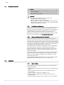
1 Safety
1.1 General safety instructions
Danger
This boiler can be used by children aged 8 years and above and
by persons with reduced physical, sensory or mental capabilities
or lack of experience and knowledge when they have been given
supervision or instruction concerning the safe use of the device
and understand the resulting risks. Children must not be allowed
to play with the appliance. Cleaning and user maintenance must
not be carried out by children without supervision.
Danger
If you smell gas:
1. Turn off the gas supply at the meter.
2. Open windows and doors in the hazardous area.
3. Do not operate light switches.
4. Do not operate any electrical equipment.
5. Do not use a telephone in the hazardous area.
6. Extinguish any naked flame and do not smoke.
7. Warn any other occupants and vacate the premises.
8. Telephone the National Gas Emergency Service on:- 0800
111 999.
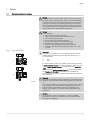
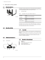
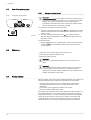
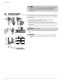
Important
If a water or gas leak occurs or is suspected, the boiler can be
isolated at the inlet valves by turning their taps through 90° (
1
/
4
turn) downwards.
A ON
B OFF
For advice please contact your Installer, Annual Service Provider
or Baxi Customer Support - The Service Division of Baxi. You can
contact Baxi Customer Support on telephone number 0344 871
1545.
When contacting Baxi Customer Support it will be useful to have
the
"Benchmark Checklist "
at the back of the Installation &
Service Manual to hand as it includes details relevant to the boiler
and installation.
Warning
Do not touch flue/chimney pipes. Depending on the settings of the
appliance, the temperature of flue/chimney pipes may exceed 60
°C.
Do not touch radiators for long periods. Depending on the settings
of the appliance, the temperature of radiators may reach 85 °C.
Take precautions with domestic hot water. Depending on the
settings of the appliance, domestic hot water temperature may
reach 65 °C.
Caution
Do not neglect to service the appliance. Contact a qualified
professional or take out a maintenance contract for the annual
servicing of the appliance.
Fig.1 Taps ON and OFF
PN-0000367
A
B
1 Safety
5

1.2 Recommendations
Caution
Only qualified professionals are authorised to work on the boiler
and the installation.
The appliance has an integral frost protection mode as long as
there is power to the boiler.
Important
Regularly check the water pressure in the system
(recommended pressure is 1.5 bar).
Keep the appliance accessible at all times.
Do not remove or cover the user information and serial number
labels affixed to the boiler control flap. They must remain legible
throughout the lifetime of the boiler.
1.2.1 The Benchmark Scheme
Baxi Heating UK Ltd is a licensed member of the Benchmark Scheme
which aims to improve the standards of installation and commissioning of
domestic heating and hot water systems in the UK and to encourage
regular servicing to optimise safety, efficiency and performance.
Benchmark is managed and promoted by Heating and Hotwater Industry
Council. For more information visit www.centralheating.co.uk
1.2.2 Benchmark Commissioning Checklist
Please ensure that the installer has fully completed the Benchmark
Checklist on the inside back pages of the installation instructions supplied
with the product and that you have signed it to say that you have received
a full and clear explanation of its operation. The installer is legally required
to complete a commissioning checklist as a means of complying with the
appropriate Building Regulations (England and Wales).
All installations must be notified, by the installer, to Local Area Building
Control either directly or through a Competent Persons Scheme. A
Building Regulations Compliance Certificate will then be issued to the
customer who should, on receipt, write the Notification Number on the
Benchmark Checklist.
This product should be serviced annually to optimise its safety, efficiency
and performance. The service engineer should complete the relevant
section of the Benchmark Service Record in the Installation & Service
manual after each service.
The completed Benchmark Checklist & proof of annual servicing (where
applicable) will be required in the event of any warranty work.
1.3 Liabilities
1.3.1 User's liability
To guarantee optimum operation of the system, you must abide by the
following instructions:
Read and follow the instructions given in the manuals provided with the
appliance.
Call on a qualified professional to carry out installation and initial
commissioning.
Get your installer to explain your installation to you.
Have the required inspections and maintenance carried out by a
qualified installer.
Keep the instruction manuals in good condition close to the appliance.
1 Safety
6

1.3.2 Installer's liability
The installer is responsible for the installation and initial commissioning of
the appliance. The installer must observe the following instructions:
Read and follow the instructions given in the manuals provided with the
appliance.
Install the appliance in compliance with prevailing legislation and
standards.
Carry out initial commissioning and any checks necessary.
Explain the installation to the user.
If maintenance is necessary, warn the user of the obligation to check the
appliance and keep it in good working order.
Give all the instruction manuals to the user.
1.3.3 Manufacturer's liability
Our products are manufactured in compliance with the requirements of all
applicable Directives and Regulations. They are therefore delivered with
the marking and any documents necessary. In the interests of the
quality of our products, we strive constantly to improve them. We therefore
reserve the right to modify the specifications given in this document.
Our liability as manufacturer may not be invoked in the following cases:
Failure to abide by the instructions on installing the appliance.
Failure to abide by the instructions on using the appliance.
Faulty or insufficient maintenance of the appliance.
1 Safety
7

2 About this manual
2.1 General
Warning
Installation, repair and maintenance must only be carried out only
by a competent person.
All Gas Safe registered engineers carry an ID card with their licence
number and a photograph. You can check your engineer is registered by
telephoning 0800 408 5500 or online at www.gassaferegister.co.uk
This manual is intended for the user of the Potterton Assure System boiler.
If the appliance is sold or transferred, or if the owner moves leaving the
appliance behind you should ensure that the manual is kept with the
appliance for consultation by the new owner and their installer.
The appliance is designed as a boiler for use in residential domestic
environments on a governed meter supply only. The selection of this boiler
is entirely at the owner’s risk. If the appliance is used for purposes other
than or in excess of these specifications, the manufacturer will not accept
any liability for resulting loss, damage or injury.
The manufacturer will not accept any liability whatsoever for loss, damage
or injury arising as a result of failure to observe the instructions for use,
maintenance and installation of the appliance.
2.2 Additional documentation
Various timers, external controls, etc. are available as optional extras. Full
details are contained in the relevant sales literature.
2.3 Symbols used
2.3.1 Symbols used in the manual
This manual uses various danger levels to draw attention to special
instructions. We do this to improve user safety, to prevent problems and to
guarantee correct operation of the appliance.
Danger
Risk of dangerous situations that may result in serious personal
injury.
Danger of electric shock
Risk of electric shock.
Warning
Risk of dangerous situations that may result in minor personal
injury.
Caution
Risk of material damage.
Important
Please note: important information.
See
Reference to other manuals or pages in this manual.
2.4 Abbreviations/glossary
CH Central heating
2 About this manual
8

DHW Domestic hot water
PCU PCB for managing burner operation
Pnc Condensing output
SU Safety PCB
2 About this manual
9

3 Technical specifications
3.1 Homologations
3.1.1 Certifications
Tab.1 Certifications
CE certificate number 0085CS0215
NOx class 6
Boiler type C
13
, C
33
3.2 Technical data
3.2.1 Technical information
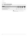
Tab.2 General
Baxi System 15 18
Gas council numbers 41 470 56
41 470 57
Tab.3 Central heating circuit specifications
BaxiSystem
All models
Maximum pressure bar 3
Minimum pressure bar 0.5
Central heating temperature adjustment °C 25/80 ± 5°
Tab.4 Electrical specifications
Baxi System
All models
Nominal electrical power supply voltage V 230
Nominal electrical power supply frequency Hz 50
Nominal power consumption when firing W 100
External fuse rating Amp 3
Tab.5 Other specifications
Baxi System
All models
Degree of protection against humidity (EN
60529)
IP IPX5D
Boiler lift weight (dry) kg 28.1
Dimensions (height/width/depth) mm H 700/W 390/D 285
Clearances (above/below casing)
front (for servicing)/(in operation)
side (left hand/right hand)
mm
mm
mm
178 / 200
450 / 5
5 / 5
These are MINIMUM recommended dimensions. Greater clearance will aid installation and maintenance.
Important
All data in this section are nominal values and subject to normal
production tolerances.
3 Technical specifications
10
Gas council numbers (LPG models)
24
41 470 59
41 470 64
n/a n/a

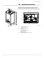
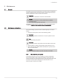
3.2.2 Dimensions and connections/clearances
Fig.2 Dimensions and connections / clearances
1
2
3
4
5
6
7
PN-0000624
9
10
The clearances shown in the diagram are minimum requirements
to allow for case removal, spanner access and air movement.
These should be observed at all times and kept clear of obstructions.
1
Condensate trap sump
2
Condensate drain
3
Heating circuit water flow
4
Gas inlet
5
Pressure relief pipe
6
Heating circuit water return
7
Pump drain point
9
Cable entry points
10
Boiler drain point on flow isolation tap
3 Technical specifications
11
700
285
390
5
5
178
200
450
5

4 Description of the product
4.1 General description
The Potterton Assure System range of fully automatic gas fired wall hung
condensing combination boilers are room sealed and fan assisted, and will
serve central heating and mains fed domestic hot water.
A Information label
Tab.6 The boiler is set to give a maximum output of :-
15 model 15 kW
16.2 kW CH Pnc (Condensing)
18 model 18 kW
19.4 kW CH Pnc (Condensing)
The boiler is factory set for use only on Natural Gas (G20) or LPG (G31).
The boiler model, serial number and Gas Council number are also shown
on the information label. This is for user reference.
4.2 Operating principle
4.2.1 In operation
Whilst the boiler is in operation cooled flue gases are discharged through
the flue gas discharge pipe. This may appear as a cloud of steam which is
normal.
Condensed water is discharged from the boiler heat exchanger into a pipe
(the condensate drain). This pipe must never be altered or re-routed
except by a qualified professional.
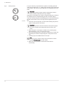
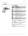
4.3 Control panel description
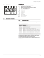
4.3.1 Description of the control panel
1 Display
2 Reset button
3 Central heating temperature control
4 Service diagnostic port
5 System water pressure gauge
Fig.3
PN-0000368
Fig.4 Control panel
PN-0000335
4 Description of the product
12
24 model
24 kW
25.8 kW CH Pnc (Condensing)
24 LPG model
24 kW
25.8 kW CH Pnc (Condensing)
Information label
A
R
Reset
bar
0
1
2
3
4
1
2
3
4
5
M
i
n
M
a
x

Display description
The following symbols may be seen on the display
OFF (frost protection still enabled)
Indicates errors that prevent the burner from starting
Error — not resettable by user
Water pressure too low
R
Indicates a resettable error
Not applicable
Not applicable
Generic error
Burner lit
Heating mode
Units for temperature
Units for pressure
4.4 Accessories and options
4.4.1 Optional accessories
The table shows the accessories available for this boiler range.
Tab.7 Optional accessories
Part number Accessory
7211473 EP2 programmer
7212443 Twin channel timer wired
720971601 Wired room thermostat
720648301 Multifit condensate & PRV combined pump
720644401 Multifit 1m condensate drain pipe 'trace heating' element
720664101 Multifit 2m Condensate drain pipe 'trace heating' element
720664201 Multifit 3m condensate drain pipe 'trace Heating' element
720664401 Multifit 5m condensate drain pipe 'trace heating' element
5121379 Multifit remote secondary PRV kit
7683087 Multifit wired outdoor sensor (System version)
For flue accessories (elbows, extensions, clamps etc.) refer to the Flue
Accessories Fitting Guide supplied in the literature pack.
Any of the above MUST be fitted ONLY by a qualified competent person.
Further details can be found in the relevant sales literature and at
www.baxi.co.uk
Fig.5 Display screen
R
PN-0000337
4 Description of the product
13

5 Operation
5.1 Start-up
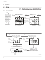
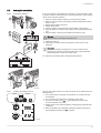
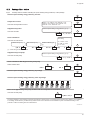
5.1.1 Operation checking procedure & basic fault identification
Fig.6 Start-up and checking
START
Make sure the gas
supply is turned ON
and check if other
gas appliances are
operating (e.g. fire,
cooker). If the
property has a
prepayment meter
ensure it has
sufficient credit.
N
O
If no gas, consult
your supplier.
Is there electricity to the
boiler ? Is the display lit ?
Check electrical supply to
boiler is switched on.
NO
YES
Is the Burner Flame
showing.
Burner Flame
(Indicates burner
is on)
Boiler operating
satisfactorily.
NO
YES
YES
YES
Is the E and R symbol
illuminated or flashing ?
YES
Press the Reset Button
(e.g. press and hold for 5 seconds)
If it does
not reset
CONTACT YOUR
INSTALLER OR
SERVICE ENGINEER.
Reset
Symbol
Is the Spanner symbol
illuminated or flashing ?
YES
Spanner
Symbol
Error
Code
Flame
Failure
OR
PN-0000391
R R
RR
Boiler
Temperature
Error
Symbol
Central
Heating
Reset
Button
5 Operation
14
R
Reset
bar
0
1
2
3
4
M
i
n
M
a
x

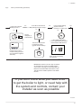
Fig.7 Start-up and checking (continued)
IMPOR
T
AN
T: Where Low Flow Taps or Fittings
are intended to be used in the DHW system
connected it is strongly recommended that the
DHW flow rate DOES NOT fall below 2.5 l/min.
This will ensure reliable operation of the DHW
function.
Is the Timer ON and
calling for heat ?
Is the Room Thermostat
(if fitted) set high enough ?
12
1
2
3
4
5
6
7
8
9
10
11
Typical
examples of
external timer
Ensure timer is set for
Central Heating ON (see
any instructions supplied
with timer)
N
O
YES
YES
NO
15
10
5
20
25
15
10
5
20
25
Turn Room Thermostat
to maximum setting
(typical example shown)
CH ON
CH OFF
bar
0
1
2
3
4
Is the Central Heating
System Pressure
between 1.0 and 2.5 bar ?
If the reading falls below
1.0 bar repressurise the system
as described in Maintenance
NO
Error Code 118 showing
low pressure.
YES
If you don’t know what you need to do
to get the boiler to light, or need help with
the system and controls, contact your
installer as soon as possible
PN-0000634
5 Operation
15

5.2 Use of the control panel
5.2.1 Using the control panel
Important
OpenTherm controller.Your installer will advise you when this type
of control is connected to the boiler. If so, any change to the boiler
settings (e.g. heating temperature) must be made using the
OpenTherm controller not the boiler control panel. Please consult
the user manual for the OpenTherm controller.
To increase or decrease the boiler temperature:
1. Turn the control knob with the symbol over it clockwise to increase
the boiler set temperature. The set temperature will be shown on the
display screen.
2. Turn the control knob with the symbol
over it anticlockwise to
decrease the boiler temperature. The temperature will be shown on
the display screen.
To reset the boiler:
1. Press the
Reset
button for approximately 1 second, holding the button
for more than 2 seconds the boiler will not reset. (see List of error
codes, page 21.)
5.3 Shutdown
Isolate the mains power supply at the fused spur unit.
Isolate the gas supply at the boiler valve.
Protect the boiler from frost.
Important
The boiler is not protected against frost once it has been shut
down.
Important
If it is anticipated that the boiler will not be used for a long period
or the property is to be unoccupied, it is advised to drain the
system if the electricity and gas supplies are to be turned off. Your
installer will be able to offer advice.
5.4 Frost protection
Where possible, draining the system should be avoided. If the system is to
be unused during winter months several precautions must be taken:
Any parts of the system that are in unheated areas of the dwelling
should be fitted with a device such as a pipe thermostat or frost
thermostat.
Power must remain supplied to the boiler and controls.
Gas must remain supplied to the boiler.
The boiler pump will operate if the system temperature drops below 7°C. If
the temperature falls to 4°C the burner will ignite and remain lit until the
temperature reaches 10°C. At this temperature the burner will extinguish
but the pump will continue to operate for 15 minutes. This feature will
protect the boiler and to some extent adjacent parts of the system but
additional devices must be incorporated to guarantee frost protection.
Fig.8 Using the control panel
PN-0000372
R
5 Operation
16
R
Reset
bar
0
1
2
3
4
M
i
n
M
a
x

6 Maintenance
6.1 General
The boiler must be serviced annually in accordance with the Installation
and Service Manual and the relevant section of the Benchmark Service
Record completed in order to maintain the warranty.
Important
Taking out a maintenance contract is recommended.
Caution
Maintenance operations must be performed by a qualified
competent person.
Use only Potterton genuine spare parts.
The painted panels should be wiped with a damp cloth and then dried
completely. DO NOT USE ABRASIVE CLEANING AGENTS.
6.2 Maintenance instructions
The central heating system should be checked regularly. Proceed as
follows:
1. Check the water pressure in the central heating system.
Important
If the water pressure is lower than 0.7 bar, the system must be
topped up.
See
Re-pressurising the system.
Important
If the water pressure drops below 0.5 bar the boiler will not work.
2. Check radiators for leaks and (especially in damp areas) for rust.
3. Open and close the radiator valves several times a year to ensure
they can still be rotated.
Caution
Only a qualified installer may clean the inside of the boiler.
6.2.1 Re-pressurising the system
If the water pressure is too low, the system must be re-pressurised.
The normal operating water pressure is between 1 and 2 bar. If the
pressure exceeds 3 bar the safety pressure valve will operate and a fault
is indicated. Ensure that the filling loop is disconnected if it is of a
temporary type. Contact your installer.
6 Maintenance
17

It may be necessary to repressurise the system occasionally (when the
water pressure falls below 0.7). A filling device (the filling loop) will be fitted
on the system. This may be on the boiler itself, or on pipework near to the
boiler.
Important
If the water pressure requires regular re-pressurising a fault or
leak is indicated. Seek advice from your installer.
Depending on which filling loop is fitted, a temporary filling loop consists of
two isolating taps and a separate filling pipe with connection fittings.
Only when repressurising should the filling pipe be connected between the
two taps. Ensure that the nuts on the pipe ends are tightened onto the
taps.
1. Fully open one of the taps first, and then while watching the pressure
gauge, carefully open the second tap.
Important
The system pressure is shown at all times on the pressure gauge
and can be viewed on the display when there is power to the
boiler.
2. When the figures on the display or needle on the pressure gauge
indicate between 1 and 1.5 bar turn both taps off.
3. Disconnect the filling pipe from the taps (a small amount of water may
be present) and remove it. Keep the pipe in a safe place for future
use.
4. If blanking caps are available fit them to the taps.
See
Go to the "How to videos" section of the "Information & advice"
page at www.baxi.co.uk for further details.
5. When the correct pressure is restored the boiler will reset
automatically.
Fig.9 Water pressure
PN-0000641
6 Maintenance
18

6.3 Venting the installation
If any air is present in the appliance or system it must be removed in order
to prevent nuisance noises that may occur during heating or when drawing
off hot water. Proceed as follows:
1. Open the valves of all the radiators connected to the system.
2. Set the room thermostat to the highest possible temperature and any
timers to ‘ON’.
3. Wait until the radiators are warm.
4. Switch off the boiler.
5. Vent the radiators. Work from the lowest radiator in the property.
6. Open the bleed vent with the key, keeping a cloth pressed against the
vent.
7. Wait until water comes out of the bleed vent and then close.
Warning
The CH water in the radiators will still be hot.
8. Switch the boiler on.
9. After venting, check that the water pressure in the system is still
adequate.
Important
If the water pressure is lower than 0.7 bar, the water must be
topped up. If necessary repressurise the system (recommended
pressure between 1 and 1.5 bar when cold).
10. Reset the room thermostat to the desired temperature.
The purpose of the function is to remove as much air as possible from the
heating system.
1. Turn off the power to the boiler and rotate the CH control knob fully
anticlockwise.
2. Turn on the power to the boiler. The display shows "000"
.
3. Turn the CH control knob ( )
1
/
4
turn clockwise twice in quick
succession (within 2 seconds).
4. Display shows "312" while de-aeration is taking place (approximately
7 minutes).
5. When de-aeration has completed, the display will show the primary
flow temperature and the CH ( ) symbols.
Fig.10 Venting the radiators
76
A
C
B
5
4
3
2
1
2
3
4
1
10
PN-0000468
Fig.11 Enabling de-aeration function
M
a
x
M
i
n
R
M
a
x
M
i
n
R
x 2
PN-0000392
6 Maintenance
19
R
Reset
bar
0
1
2
3
4
M
i
n
M
a
x

Caution
If the system is drained (even partly, when replacing a radiator for
example) the de-aeration function must be repeated. Also the
inhibitor concentration must be checked and replenished if
necessary.
6.4 Draining the installation
It may be necessary to drain the central heating system if radiators need
to be replaced, if there is a major water leak or if there is a risk of freezing.
Proceed as follows:
1. Open the valves of all the radiators connected to the system.
2. Switch off the boiler's electrical connection.
3. Wait approximately ten minutes, until the radiators feel cold.
4. Connect a drain hose to the lowest draining point. Place the end of the
hose in a drain or at a place where drained pipe water will not cause
any damage.
5. Open the central heating system fill/drain valve. Drain the installation.
Warning
The water may still be hot.
6. Close the drain valve when no more water comes from the draining
point.
Important
After draining the system, the concentration of corrosion inhibitor
and antifreeze agent may be extremely diluted - check with your
installer.
Fig.12 Draining the installation
AD-3000730-01
5
3
2
1
2
3
4
1
4
6 Maintenance
20
Page is loading ...
Page is loading ...
Page is loading ...
Page is loading ...
Page is loading ...
Page is loading ...
Page is loading ...
Page is loading ...
Page is loading ...
Page is loading ...
Page is loading ...
Page is loading ...
-
 1
1
-
 2
2
-
 3
3
-
 4
4
-
 5
5
-
 6
6
-
 7
7
-
 8
8
-
 9
9
-
 10
10
-
 11
11
-
 12
12
-
 13
13
-
 14
14
-
 15
15
-
 16
16
-
 17
17
-
 18
18
-
 19
19
-
 20
20
-
 21
21
-
 22
22
-
 23
23
-
 24
24
-
 25
25
-
 26
26
-
 27
27
-
 28
28
-
 29
29
-
 30
30
-
 31
31
-
 32
32


Baxi 600 System User guide
- Category
- Water heaters & boilers
- Type
- User guide
- This manual is also suitable for
Ask a question and I''ll find the answer in the document
Finding information in a document is now easier with AI
Related papers
-
Baxi 600 Combi User guide
-
-
-
-
-
-
-
Baxi EcoBlue Advance Combi 28 Quick start guide
-
-
Other documents
-
 De Dietrich User instruction card User guide
-
 Main Combi 24 HE User manual
-
Potterton Potterton Gold Combi 28 HE A User manual
-
Danfoss RAW User guide
-
-
Baxi Potterton Gold FSB 30 HE User manual
-
-
Potterton 47-393-42 User manual
-
 Main Heating Main Eco Elite Combi 30 User manual
-


