Vega VEGACAL 63 Product information

Category
Measuring, testing & control
Type
Product information

This manual is also suitable for

Product information
Capacitive
Level measurement in liquid
VEGACAL 62
VEGACAL 63
VEGACAL 64
VEGACAL 66
VEGACAL 69
Document ID: 30138
2
Contents
Capacitive
30138-EN-160930
Contents
1 Description of the measuring principle ............................................................................................................................................................... 3
2 Type overview .........................................................................................................................................................................................................5
3 Housing overview ..................................................................................................................................................................................................6
4 Mounting instructions ........................................................................................................................................................................................... 7
5 Electrical connection ............................................................................................................................................................................................. 9
6 Adjustment ........................................................................................................................................................................................................... 10
7 Dimensions ...........................................................................................................................................................................................................12
Take note of safety instructions for Ex applications
Please note the Ex specic safety information that you can nd at www.vega.com and that comes with each instrument. In hazardous areas
you should take note of the appropriate regulations, conformity and type approval certicates of the sensors and power supply units. The sen-
sors must only be operated on intrinsically safe circuits. The permissible electrical values are stated in the certicate.
3
Description of the measuring principle
Capacitive
30138-EN-160930
1 Description of the measuring principle
Measuring principle
Probe, measured product and vessel wall form an electrical capacitor.
The capacitance is inuenced by three main factors.
1
2
3
Fig. 1: Functional principle - Plate capacitor
1 Distance between the electrode surfaces
2 Size of the electrode surfaces
3 Type of dielectric between the electrodes
The probe and the vessel wall are the capacitor plates. The measured
product is the dielectric. Due to the higher dielectric constant of the prod-
uct compared to air, the capacitance increases as the probe is gradually
covered.
The capacitance as well as the resistance change are converted by the
electronics module into a level-proportional signal.
The more constant the conductivity, concentration and temperature of a
product, the better the conditions for admittance measurement. Changes
in the measuring conditions are generally less critical when detecting
materials with high DK values.
The sensors are maintenance free and rugged and can be implemented
in all areas of industrial measurement engineering.
Admittance probes have no minimum distances or dead band in which
measurement is not possible.
Whereas partly insulated versions are predominantly used for solids, fully
insulated versions are preferred for liquids.
Corrosive and adhesive products
Implementation in very adhesive or corrosive products is no problem.
Since the admittance measuring principle places no special require-
ments on mounting, a host of dierent applications can be equipped with
VEGACAL series 60 probes.
Wide application range
With measuring ranges up to 32 m (105 ft), the sensors are well suited
for tall vessels. Temperatures up to 200 °C (392 °F) and pressures from
vacuum to 64 bar (928 psig) cover a wide range of applications.
1.2 Application examples
Liquid vessels up to 6 m high
1
Fig. 2: Small liquid tank
1 Fully insulated rod probe VEGACAL 63
Admittance probes can be used in liquid vessels where products are
stored or further processed. To avoid incorrect measuring results in
applications with non-conductive products, the measured medium must
always remain the same. A change of the medium (dierent dielectric
value) necessitates a fresh calibration. When the conductivity is approx.
100 µS/cm or above, dierent products or even mixtures can be meas-
ured without renewed calibration.
The dielectric value determines whether a partly or fully insulated probe
must be used. If the value is in the range up to 5, a partly insulated probe
will be sucient, from 5 on, a fully insulated probe should be used.
Because admittance measuring probes have no dead band and impose
no restrictions on mounting, they are well suited for small vessels. The
measuring probes are not aected by high sockets and wall distances
upwards of approx. 100 mm.
Advantages:
No dead bands
Low min. distance
Unaected by sockets and vessel installations
High chemical resistance
4
Description of the measuring principle
Capacitive
30138-EN-160930
Liquid vessels higher than 6 m and vessels in roofed-over
spaces
1
Fig. 3: High liquid tank
1 Fully insulated cable probe VEGACAL 66 mounted with straining spring
Cable measuring probes are preferred for tall vessels (higher than 6 m)
and vessels situated in roofed-over spaces. Meas. lengths up to 32 m
enable installation in very tall vessels. Flexible cable probes allow easy
installation even in tight quarters.
Since the distance to the vessel wall should be stable,securing the grav-
ity weight to the bottom of the vessel is recommended.
Advantages:
Long meas. lengths
No dead band
Low min. distance
Unaected by sockets and vessel installations
High chemical resistance
Vessel with adhesive, conductive liquids
1
Fig. 4: Level measurement in very adhesive liquids
1 Fully insulated rod probe VEGACAL 64 for adhesive products
Whereas electrically non-conductive products are no problem for admit-
tance measurement, adhesive, conductive products cause measurement
errors. Due to the mechanical construction of VEGACAL 64 and the
admittance processing, this eect is neutralised. Even strong conduc-
tive buildup is compensated and thus does not rule out good measuring
results.
Advantages:
Immune even to heavy buildup
No dead bands
Low min. distance
Unaected by sockets and vessel installations
5
Type overview
Capacitive
30138-EN-160930
2 Type overview
VEGACAL 62 VEGACAL 63 VEGACAL 64
Preferred applications Liquids, non-conductive Liquids, conductive Liquids, conductive
Version Rod - partly insulated Rod - fully insulated Rod - fully insulated
Suitable for very adhesive products
Insulation PTFE PE, PTFE FEP
Length 0.2 … 6 m (0.656 … 19.69 ft) 0.2 … 6 m (0.656 … 19.69 ft) 0.2 … 4 m (0.656 … 13.12 ft)
Process tting Thread from G¾, anges Thread from G¾, anges Thread from G1, anges
Process temperature -50 … +200 °C (-58 … +392 °F) -50 … +200 °C (-58 … +392 °F) -50 … +200 °C (-58 … +392 °F)
Process pressure -1 … 64 bar/-100 … 6400 kPa (-
14.5 … 928 psig)
-1 … 64 bar/-100 … 6400 kPa (-
14.5 … 928 psig)
-1 … 64 bar/-100 … 6400 kPa (-
14.5 … 928 psig)
VEGACAL 66 VEGACAL 69
Preferred applications Solids, liquids Liquids
Version Cable - insulated Double rod - fully insulated
Insulation PTFE FEP
Length 0.4 … 32 m (1.312 … 105 ft) 0.2 … 4 m (0.656 … 13.12 ft)
Process tting Thread from G¾, anges Flange (PP or PTFE)
Process temperature -50 … +200 °C (-58 … +392 °F) -40 … +100 °C (-40 … +212 °F)
Process pressure -1 … 64 bar/-100 … 6400 kPa (-
14.5 … 928 psig)
-1 … 2 bar/-100 … 200 kPa (-
14.5 … 29 psig)
6
Housing overview
Capacitive
30138-EN-160930
3 Housing overview
Plastic PBT
Protection rating IP 66/IP 67 IP 66/IP 67
Version Single chamber Double chamber
Application area Industrial environment Industrial environment
Aluminium
Protection rating IP 66/IP 67, IP 66/IP 68 (1 bar) IP 66/IP 67, IP 66/IP 68 (1 bar)
Version Single chamber Double chamber
Application area Industrial environment with increased me-
chanical stress
Industrial environment with increased me-
chanical stress
Stainless steel 316L
Protection rating IP 66/IP 67 IP 66/IP 67, IP 66/IP 68 (1 bar) IP 66/IP 67, IP 66/IP 68 (1 bar)
Version Single chamber, electropolished Single chamber, precision casting Double chamber, precision casting
Application area Aggressive environment, food processing,
pharmaceutical
Aggressive environment, extreme mechani-
cal stress
Aggressive environment, extreme mechani-
cal stress
7
Mounting instructions
Capacitive
30138-EN-160930
4 Mounting instructions
Pressure/Vacuum
The process tting must be sealed if there is gauge or low pressure in
the vessel. Check if the seal material is resistant against the measured
product and the process temperature.
Insulating measures in metal vessels such as e.g. covering the thread
with teon tape can interrupt the necessary electrical connection to the
vessel. Ground the probe on the vessel.
Mounting socket
In adhesive products, the probe should protrude into the vessel (horizon-
tal mounting), to avoid buildup. In such cases, avoid sockets for anges
and threaded ttings.
Measuring range
Please note that with fully insulated cable probes, measurement in the
area of the gravity weight is not possible (L - length of the gravity weight).
With fully insulated rod probes, measurement is not possible within the
20 mm of the probe tip (L - 20 mm).
If necessary, use a correspondingly longer meas. probe.
Agitators
Excessive system vibration or shocks, e.g. caused by agitators or
turbulence in the vessel (e.g. from uidisation) can cause the probe of
VEGACAL to vibrate in resonance. This can lead to increased material
stress. Should a longer rod probe be necessary, you can provide a suit-
able support or guy directly above the end of the probe to stabilise it.
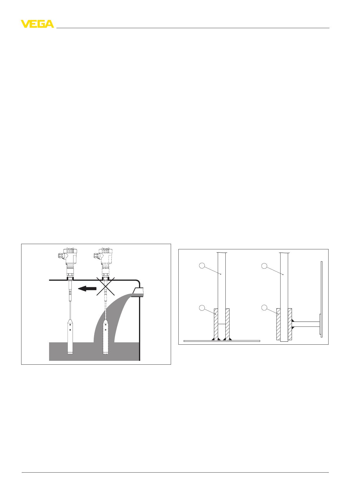
Inowing medium
If VEGACAL is mounted in the lling stream, unwanted false measure-
ment signals can be generated. For this reason, mount VEGACAL at a
position in the vessel where no disturbances, e.g. from lling openings,
agitators, etc., can occur.
This applies particularly to instrument versions with a longer probe.
Fig. 17: Inowing medium
Vessel forms
If possible, the admittance probe should be mounted vertically or parallel
to the counter electrode. This applies particularly to applications in non-
conductive products.
In cylindrical tanks, spherical tanks or other asymmetrical tank forms,
nonlinear level values are generated due to the varying distance to the
vessel wall.
Use a double rod electrode, a concentric tube or linearise the measuring
signal.
Vessel material
Metal vessel
Make sure that the mechanical connection of the probe to the vessel is
electrically conductive to ensure sucient grounding.
Use conductive seals, such as those made of copper or lead, etc. Insulat-
ing measures, such as covering the thread with Teon tape, can interrupt
the necessary electrical connection with metal vessels. For this reason,
ground the probe on the vessel or use a conductive seal material.
Non-conductive vessels
In non-conductive vessels, e.g. plastic tanks, the second pole of the
capacitor must be provided separately. Use a double rod electrode or
mount a concentric tube.
Operating temperatures
If the housing is subject to high ambient temperatures, you have to either
use a temperature adapter or disconnect the electronics from the probe
and install it in a separate housing at a cooler place.
Make sure that the probe is not covered by an existing vessel insulation.
The temperature ranges of the probes are listed in chapter "Technical
data".
Corrosive, abrasive products
Various isolating materials are available for very corrosive or abrasive
products. If metal is not chemically resistant to the medium, use a plated
ange.
Fasten
Rod versions
During operation, the probe must not touch any installations or the vessel
wall. The measured value can also change if the distance to the vessel
wall changes considerably. If necessary, secure the end of the probe
(insulated).
1
2
1
2
Fig. 18: Fasten the probe
1 Probe - fully insulated
2 Metal socket
3 Probe - bare
4 Plastic or ceramic socket
Cable versions
Long cable versions are particularly susceptible to product movement,
i.e. they may touch the vessel wall if the forces are strong enough. For
that reason, the measuring probe should be rmly secured.
In the gravity weight there is a thread (M12), e.g. for a ring bolt (article no.
2.27424). The thread is already insulated in the gravity weight.
Make sure that the probe cable is not completely taut. Avoid tensile loads
on the cable. In our line of accessories you will nd a straining spring that
can be applied to avoid cable overload.
8
Mounting instructions
Capacitive
30138-EN-160930
1
3
2
Fig. 19: Fasten the probe
1 Gravity weight (316L)
2 Threaded insert M12 insulated, of PEEK
3 Ring bolt M12 of 316L (article no. 2.27423)
In vessels with conical bottom it can be advantageous to mount the sen-
sor in the centre of the vessel, as measurement is then possible down to
the bottom.
Measurement is not possible over the length of the gravity weight of the
fully insulated probe. The measuring range of the probe ends at the up-
per edge of the gravity weight.
Protective cover
To protect the sensor against pollution and strong heat due to the sun,
you can snap a weather protective cover onto the sensor housing.
Fig. 20: Weather protection cover in dierent versions
9
Electrical connection
Capacitive
30138-EN-160930
5 Electrical connection
5.1 General requirements
The supply voltage range can dier depending on the instrument version.
You can nd exact specications in chapter "Technical data".
The national installation standards as well as the valid safety regulations
and accident prevention rules must be observed.
In hazardous areas you must take note of the respective regula-
tions, conformity and type approval certicates of the sensors and
power supply units.
5.2 Voltage supply
General information
Supply voltage and current signal are carried on the same two-wire
cable. The requirements on the power supply are specied in chapter
"Technical data".
Two-wire 4 … 20 mA/HART, > 4 … < 20 mA
The VEGA power supply units VEGATRENN 149AEx, VEGASTAB 690,
VEGADIS 371 as well as VEGAMET signal conditioning instruments are
suitable for power supply. When one of these instruments is used, a reli-
able separation of the supply circuits from the mains circuits according to
DIN VDE 0106 part 101 is ensured for the sensor.
Probus PA
Power is supplied by a Probus DP/PA segment coupler or a VEGALOG
571 EP input card.
Fig. 21: Integration of instruments in a Probus PA system via segment coupler DP/
PA or data recording systems with Probus PA input card
Foundation Fieldbus
Power supply via the H1 Fieldbus cable.
5.3 Connection cable
General information
The sensors are connected with standard cable without screen. An outer
cable diameter of 5 … 9 mm ensures the seal eect of the cable entry.
Two-wire 4 … 20 mA/HART, > 4 … < 20 mA
If electromagnetic interference is expected, screened cable should be
used for the signal lines.
Probus PA, Foundation Fieldbus
The installation must be carried out according to the appropriate bus
specication. The sensor is connected respectively with screened cable
according to the bus specication. Make sure that the bus is terminated
via appropriate terminating resistors.
For power supply, an approved installation cable with PE conductor is
also required.
In Ex applications, the corresponding installation regulations must
be noted for the connection cable.
5.4 Connection of the cable screen and grounding
Two-wire 4 … 20 mA/HART, > 4 … < 20 mA
The cable screen must be connected on both ends to ground potential.
If potential equalisation currents are expected, the connection on the
evaluation side must be made via a ceramic capacitor (e.g. 1 nF, 1500 V).
Probus PA, Foundation Fieldbus
In systems with potential separation, the cable screen is connected di-
rectly to ground potential on the power supply unit, in the connection box
and directly on the sensor.
In systems without potential equalisation, connect the cable screen di-
rectly to ground potential only at the power supply unit and at the sensor
- do not connect to ground potential in the connection box or T-distributor.
5.5 Wiring plan
Single chamber housing
I
2
C
Display
1
12 5 678
Fig. 22: Connection HART two-wire, Probus PA, Foundation Fieldbus
1 Voltage supply and signal output
Two-wire output > 4 … < 20 mA
1
12
Fig. 23: Connection > 4 … < 20 mA (not standardised) for connection to a signal
conditioning instrument
1 Voltage supply/Signal output
Double chamber housing - two-wire
I
2
C
1
12
Fig. 24: Connection HART two-wire, Probus PA, Foundation Fieldbus
1 Voltage supply and signal output
10
Adjustment
Capacitive
30138-EN-160930
6 Adjustment
6.1 Adjustment on the measurement loop
Via the display and adjustment module through keys
The plug-in display and adjustment module is used for measured value
indication, adjustment and diagnosis. It is equipped with an illuminated
full dot matrix as well as four keys for adjustment.
Fig. 25: Display and adjustment module with single chamber housing
Via the display and adjustment module through magnetic pen
With the Bluetooth version of the display and adjustment module, the
sensor can also be adjusted with the magnetic pen. This is done right
through the closed lid (with inspection window) of the sensor housing.
Fig. 26: Display and adjustment module - with adjustment via magnetic pen
Via a PC with PACTware/DTM
The interface converter VEGACONNECT is required for connection of
the PC. The converter is placed on the sensor instead of the display and
adjustment module and connected to the USB interface of the PC.
2
3
1
4
Fig. 27: Connection of the PC via VEGACONNECT and USB
1 VEGACONNECT
2 Sensor
3 USB cable to the PC
4 PC with PACTware/DTM
PACTware is an adjustment software for conguration, parameter adjust-
ment, documentation and diagnosis of eld devices. The corresponding
device drivers are called DTMs.
6.2 Operation in the measurement loop environ-
ment - wireless via Bluetooth
Via a smartphone/tablet
The display and adjustment module with integrated Bluetooth functional-
ity allows wireless connection to smartphones/tablets with iOS or Android
operating system. The adjustment is carried out via the VEGA Tools app
from the Apple App Store or Google Play Store.
1
2
3
Fig. 28: Wireless connection to smartphones/tables
1 Display and adjustment module
2 Sensor
3 Smartphone/Tablet
Via a PC with PACTware/DTM
The wireless connection from the PC to the sensor is carried out via
the Bluetooth USB adapter and a display and adjustment module with
integrated Bluetooth function. The adjustment is carried out via the PC
with PACtware/DTM.
2
1
4
3
Fig. 29: Connection of the PC via Bluetooth adapter
1 Display and adjustment module
2 Sensor
3 Bluetooth USB adapter
4 PC with PACTware/DTM
6.3 Adjustment carried out at position remote from
the measuring point - wired
Via external display and adjustment units
For this, the external display and adjustment units VEGADIS 81 and 82
are available. The adjustment is carried out via the keys of the built-in
display and adjustment module.
The VEGADIS 81 is mounted at a distance of 50 m from the sensor and
directly to the sensor electronics. VEGADIS 82 is looped directly into the
signal cable at any point.
11
Adjustment
Capacitive
30138-EN-160930
4
1
3
2
5
4
Fig. 30: Connection of VEGADIS 81 to the sensor
1 Voltage supply/Signal output sensor
2 Sensor
3 Connection cable sensor - external display and adjustment unit
4 External display and adjustment unit
5 Display and adjustment module
4
5
3
1
2
Fig. 31: Connection of VEGADIS 82 to the sensor
1 Voltage supply/Signal output sensor
2 External display and adjustment unit
3 Display and adjustment module
4 4 … 20 mA/HART signal cable
5 Sensor
Via a PC with PACTware/DTM
The sensor adjustment is carried out via a PC with PACTware/DTM.
4
5
6
3
2
1
Fig. 32: Connection of VEGADIS 82 to the sensor, adjustment via PC with PACT-
ware
1 Voltage supply/Signal output sensor
2 External display and adjustment unit
3 VEGACONNECT
4 4 … 20 mA/HART signal cable
5 Sensor
6 PC with PACTware/DTM
6.4 Adjustment carried out at position remote from
the measuring point - wireless through mobile
network
As an option, the radio module PLICSMOBILE can be mounted into a
plics
®
sensor with double chamber housing. It is used for transmission of
measured values and for remote parameter adjustment of the sensor.
Fig. 33: Transmission of measured values and remote parameter adjustment of the
sensor via mobile phone network.
6.5 Alternative adjustment programs
DD adjustment programs
Device descriptions as Enhanced Device Description (EDD) are available
for DD adjustment programs such as, for example, AMS™ and PDM.
The les can be downloaded at www.vega.com/downloads under "Soft-
ware".
Field Communicator 375, 475
Device descriptions for the instrument are available as EDD for param-
eter adjustment with the Field Communicator 375 or 475.
For the integration of the EDD in the Field Communicator 375 or 475, the
software "Easy Upgrade Utility" is required which is available from the
manufacturer. This software is updated via the Internet and new EDDs
are automatically taken over into the device catalogue of this software
after they are released by the manufacturer. They can then be transferred
to a Field Communicator.
12
Dimensions
Capacitive
30138-EN-160930
7 Dimensions
Housing
~ 69 mm
(2.72")
ø 77 mm
(3.03")
112 mm (4
13
/
32
")
M20x1,5/
½ NPT
~ 69 mm
(2.72")
ø 77 mm
(3.03")
117 mm (4.61")
M20x1,5/
½ NPT
~ 87 mm (3.43")
M16x1,5
ø 84 mm
(3.31")
120 mm (4.72")
M20x1,5/
½ NPT
~ 116 mm (4.57")
ø 84 mm (3.31")
116 mm (4.57")
M20x1,5M20x1,5/
½ NPT
~ 59 mm
(2.32")
ø 80 mm
(3.15")
112 mm (4.41")
M20x1,5/
½ NPT
1
3
4
5
2
Fig. 34: Housing versions
1 Plastic housing
2 Stainless steel housing
3 Stainless steel housing - precision casting
4 Aluminium double chamber housing
1)
5 Aluminium housing
VEGACAL 62
ø 16 mm
(0.63")
100 mm
(3.94")
12 mm
(0.47")
L
G ¾, G 1, G 1½
56 mm
(2.21")
22 mm
(0.87”)
Fig. 35: VEGACAL 62 - threaded version
L Sensor length, see chapter "Technical data"
VEGACAL 63
ø 16mm
(0.63")
L
G¾, G 1, G 1½
56 mm
(2.21")
22 mm
(0.86")
Fig. 36: VEGACAL 63 - threaded version
L Sensor length, see chapter "Technical data"
VEGACAL 64
ø 16mm
(0.63")
L
G¾, G 1, G 1½
56 mm
(2.21")
22 mm
(0.86")
Fig. 37: VEGACAL 64 - threaded version
L Sensor length, see chapter "Technical data"
1)
Not with electronics version two-wire output > 4 … < 20 mA.
13
Dimensions
Capacitive
30138-EN-160930
VEGACAL 66
177 mm
(7.87")
ø 8 mm
(0.32")
L
G 1
G 1½
56 mm
(2.21")
ø 30 mm
(1.18")
22 mm
(0.87")
Fig. 38: VEGACAL 66 - threaded version
L Sensor length, see chapter "Technical data"
VEGACAL 69
ø 14 mm
(0.55")
47 mm
(1.85")
L
25 mm
(0.98")
87,5 mm
(3.45")
Fig. 39: VEGACAL 69
L Sensor length, see chapter "Technical data"
14
Notes
Capacitive
30138-EN-160930
15
Notes
Capacitive
30138-EN-160930
VEGA Grieshaber KG
Am Hohenstein 113
77761 Schiltach
Germany
30138-EN-160930
All statements concerning scope of delivery, application, practical use and operating conditions of the sensors and processing systems correspond to the information
available at the time of printing.
Subject to change without prior notice
© VEGA Grieshaber KG, Schiltach/Germany 2016
Phone +49 7836 50-0
Fax +49 7836 50-201
www.vega.com
  • Page 1 1
  • Page 2 2
  • Page 3 3
  • Page 4 4
  • Page 5 5
  • Page 6 6
  • Page 7 7
  • Page 8 8
  • Page 9 9
  • Page 10 10
  • Page 11 11
  • Page 12 12
  • Page 13 13
  • Page 14 14
  • Page 15 15
  • Page 16 16

Vega VEGACAL 63 Product information

Category
Measuring, testing & control
Type
Product information
This manual is also suitable for

Ask a question and I''ll find the answer in the document

Finding information in a document is now easier with AI