Miller KE607495 Owner's manual
- Category
- Welding System
- Type
- Owner's manual
This manual is also suitable for

cover 7/93 – SB-129 229-A PRINTED IN USA
1997 MILLER Electric Mfg. Co.
Read and follow these instructions and all
safety blocks carefully.
Have only trained and qualified persons
install, operate, or service this unit.
Call your distributor if you do not understand
the directions.
Give this manual to the operator.
For help, call your distributor
or: MILLER Electric Mfg. Co., P.O. Box 1079,
Appleton, WI 54912 414-734-9821
OWNER’S
MANUAL
OM-894 127 412C
September 1997
Intellitig 40

Miller Electric manufactures a full line
of welders and welding related equipment.
For information on other quality Miller
products, contact your local Miller distributor
to receive the latest full line catalog or
individual catalog sheets. To locate your nearest
distributor or service agency call 1-800-4-A-Miller,
or visit us at www.MillerWelds.com on the web.
Thank you and congratulations on choosing Miller. Now
you can get the job done and get it done right. We know
you don’t have time to do it any other way.
That’s why when Niels Miller first started building arc
welders in 1929, he made sure his products offered
long-lasting value and superior quality. Like you, his
customers couldn’t afford anything less. Miller products
had to be more than the best they could be. They had to
be the best you could buy.
Today, the people that build and sell Miller products continue the
tradition. They’re just as committed to providing equipment and service
that meets the high standards of quality and value established in 1929.
This Owner’s Manual is designed to help you get the most out of your
Miller products. Please take time to read the Safety precautions. They will
help you protect yourself against potential hazards on the worksite. We’ve
made installation and operation quick and easy.
With Miller you can count on years of reliable
service with proper maintenance. And if for
some reason the unit needs repair, there’s a
Troubleshooting section that will help you
figure out what the problem is. The parts list
will then help you to decide which exact part
you may need to fix the problem. Warranty and
service information for your particular model
are also provided.
Miller is the first welding
equipment manufacturer in
the U.S.A. to be registered to
the ISO 9001 Quality System
Standard.
Working as hard as you do
– every power source from
Miller is backed by the most
hassle-free warranty in the
business.
From Miller to You
Miller offers a Technical
Manual which provides
more detailed service and
parts information for your
unit. To obtain a Technical
Manual, contact your local
distributor. Your distributor
can also supply you with
Welding Process Manuals
such as SMAW, GTAW,
GMAW, and GMAW-P.

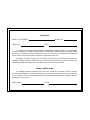
CERTIFICATE
NAME OF EQUIPMENT: MODEL NO.
SERIAL NO. DATE:
This equipment has been type-tested under standardized field test conditions as recommended
by the Joint Industry Committee on High-Frequency Stabilized Arc Welding Machines found to radiate
less than 10 microvolts per meter at a distance of one mile, the maximum allowable limit established
by the Federal Communications Commission for equipment of this type.
Installations using this equipment on the basis of these tests, may reasonably be expected to
meet the radiation limitations established by the Federal Communications Commission, only when
installed, operated and maintained as specified in the instruction book provided.
USER’S CERTIFICATION
The welding equipment identified above has been installed in accordance with the specific
instructions applicable to this model as outlined in the instruction book furnished. It is being used only
for the purpose for which it was intended and is being maintained and operated in accordance with the
manufacturer’s instructions
Date Installed Signed


OM-894C – 9/97
TABLE OF CONTENTS
Section No. Page No.
SECTION 1 – SAFETY RULES FOR OPERATION OF ARC WELDING POWER SOURCE
1-1. Introduction 1. . . . . . . . . . . . . . . . . . . . . . . . . . . . . . . . . . . . . . . . . . . . . . . . .
1-2. General Precautions 1. . . . . . . . . . . . . . . . . . . . . . . . . . . . . . . . . . . . . . . . .
1-3. Arc Welding 4. . . . . . . . . . . . . . . . . . . . . . . . . . . . . . . . . . . . . . . . . . . . . . . . .
1-4. Standards Booklet Index 5. . . . . . . . . . . . . . . . . . . . . . . . . . . . . . . . . . . . . .
SECTION 2 – SAFETY PRECAUTIONS AND SIGNAL WORDS
2-1. General Information And Safety 6. . . . . . . . . . . . . . . . . . . . . . . . . . . . . . .
2-2. Safety Alert Symbol And Signal Words 6. . . . . . . . . . . . . . . . . . . . . . . . .
SECTION 3 – SPECIFICATIONS
3-1. Description 7. . . . . . . . . . . . . . . . . . . . . . . . . . . . . . . . . . . . . . . . . . . . . . . . .
SECTION 4 – INSTALLATION OR RELOCATION
4-1. Location 7. . . . . . . . . . . . . . . . . . . . . . . . . . . . . . . . . . . . . . . . . . . . . . . . . . . .
4-2. Setting DIP Switch SW1 7. . . . . . . . . . . . . . . . . . . . . . . . . . . . . . . . . . . . . .
4-3. Shielding Gas Connections 9. . . . . . . . . . . . . . . . . . . . . . . . . . . . . . . . . . .
4-4. Remote Operator Control Connections 9. . . . . . . . . . . . . . . . . . . . . . . . .
4-5. Welding Power Source Connections 10. . . . . . . . . . . . . . . . . . . . . . . . . . .
4-6. Weld Input/Output Connections 10. . . . . . . . . . . . . . . . . . . . . . . . . . . . . . . .
4-7. Optional Internal Wiring Connections 11. . . . . . . . . . . . . . . . . . . . . . . . . . .
SECTION 5 – OPERATOR CONTROLS
5-1. Power Switch 13. . . . . . . . . . . . . . . . . . . . . . . . . . . . . . . . . . . . . . . . . . . . . . .
5-2. Program/Run/Reset Key Switch 13. . . . . . . . . . . . . . . . . . . . . . . . . . . . . . .
5-3. Mode Selector Switch 13. . . . . . . . . . . . . . . . . . . . . . . . . . . . . . . . . . . . . . . .
5-4. Parameter Select Push Button 13. . . . . . . . . . . . . . . . . . . . . . . . . . . . . . . .
5-5. Up Push Button 14. . . . . . . . . . . . . . . . . . . . . . . . . . . . . . . . . . . . . . . . . . . . .
5-6. Down Push Button 14. . . . . . . . . . . . . . . . . . . . . . . . . . . . . . . . . . . . . . . . . . .
5-7. Purge Push Button 14. . . . . . . . . . . . . . . . . . . . . . . . . . . . . . . . . . . . . . . . . .
5-8. Gas Control 14. . . . . . . . . . . . . . . . . . . . . . . . . . . . . . . . . . . . . . . . . . . . . . . . .
5-9. Gas Flow Rate Digital Meter 14. . . . . . . . . . . . . . . . . . . . . . . . . . . . . . . . . .
5-10. Digital Display 14. . . . . . . . . . . . . . . . . . . . . . . . . . . . . . . . . . . . . . . . . . . . . . .
5-11. Weld Amperes Meter 15. . . . . . . . . . . . . . . . . . . . . . . . . . . . . . . . . . . . . . . . .
5-12. Remote Operator Control 15. . . . . . . . . . . . . . . . . . . . . . . . . . . . . . . . . . . . .
SECTION 6 – PROGRAMMING
6-1. General 15. . . . . . . . . . . . . . . . . . . . . . . . . . . . . . . . . . . . . . . . . . . . . . . . . . . .
6-2. Displays 15. . . . . . . . . . . . . . . . . . . . . . . . . . . . . . . . . . . . . . . . . . . . . . . . . . . .
6-3. Modes Of Operation 16. . . . . . . . . . . . . . . . . . . . . . . . . . . . . . . . . . . . . . . . .
6-4. Entering A Program 16. . . . . . . . . . . . . . . . . . . . . . . . . . . . . . . . . . . . . . . . . .
6-5. Editing A Program 16. . . . . . . . . . . . . . . . . . . . . . . . . . . . . . . . . . . . . . . . . . .
6-6. Dry Run 17. . . . . . . . . . . . . . . . . . . . . . . . . . . . . . . . . . . . . . . . . . . . . . . . . . . .

6-7. Stop Watch Feature 17. . . . . . . . . . . . . . . . . . . . . . . . . . . . . . . . . . . . . . . . . .
6-8. Linking Programs 17. . . . . . . . . . . . . . . . . . . . . . . . . . . . . . . . . . . . . . . . . . . .
6-9. Combining Programs 17. . . . . . . . . . . . . . . . . . . . . . . . . . . . . . . . . . . . . . . . .
6-10. Running A Program 18. . . . . . . . . . . . . . . . . . . . . . . . . . . . . . . . . . . . . . . . . .
SECTION 7 – SEQUENCE OF OPERATION
7-1. Gas Tungsten Arc Welding (GTAW) 19. . . . . . . . . . . . . . . . . . . . . . . . . . . .
7-2. Shutting Down 19. . . . . . . . . . . . . . . . . . . . . . . . . . . . . . . . . . . . . . . . . . . . . .
SECTION 8 – MAINTENANCE & TROUBLESHOOTING
8-1. Routine Maintenance 20. . . . . . . . . . . . . . . . . . . . . . . . . . . . . . . . . . . . . . . . .
8-2. Overload Protection 20. . . . . . . . . . . . . . . . . . . . . . . . . . . . . . . . . . . . . . . . . .
8-3. Tungsten Electrode 20. . . . . . . . . . . . . . . . . . . . . . . . . . . . . . . . . . . . . . . . . .
8-4. Circuit Board Handling Precautions 22. . . . . . . . . . . . . . . . . . . . . . . . . . . .
8-5. Diagnostic Program 22. . . . . . . . . . . . . . . . . . . . . . . . . . . . . . . . . . . . . . . . . .
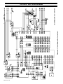
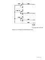
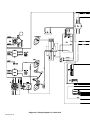
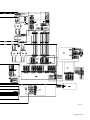
SECTION 9 – ELECTRICAL DIAGRAMS
Diagram 9-1. Circuit Diagram For Control Unit 36. . . . . . . . . . . . . . . . . . . . . . . . .
Diagram 9-2. Circuit Diagram For Remote Operator Control 37. . . . . . . . . . . . . .
Diagram 9-3. Wiring Diagram For Control Unit 38. . . . . . . . . . . . . . . . . . . . . . . . .
SECTION 10 – CERTIFICATION FOR HIGH FREQUENCY ARC WELDING EQUIPMENT
10-1. General 40. . . . . . . . . . . . . . . . . . . . . . . . . . . . . . . . . . . . . . . . . . . . . . . . . . . .
10-2. Definitions 40. . . . . . . . . . . . . . . . . . . . . . . . . . . . . . . . . . . . . . . . . . . . . . . . . .
10-3. High-Frequency Radiation 41. . . . . . . . . . . . . . . . . . . . . . . . . . . . . . . . . . . .
10-4. Location 41. . . . . . . . . . . . . . . . . . . . . . . . . . . . . . . . . . . . . . . . . . . . . . . . . . . .
10-5. General Installation Procedures 41. . . . . . . . . . . . . . . . . . . . . . . . . . . . . . .
10-6. Guidelines For Installation Of High-Frequency Assisted Arc Welding
Power Sources 43. . . . . . . . . . . . . . . . . . . . . . . . . . . . . . . . . . . . . . . . . . . . . .
10-7. Installation Guidelines Checklist 43. . . . . . . . . . . . . . . . . . . . . . . . . . . . . . .
SECTION 11 – PARTS LIST
Figure 11-1. Main Assembly 44. . . . . . . . . . . . . . . . . . . . . . . . . . . . . . . . . . . . . . . . .
Figure 11-2. Pendant 47. . . . . . . . . . . . . . . . . . . . . . . . . . . . . . . . . . . . . . . . . . . . . . .
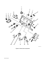
Figure 11-3. Panel, Rear w/Components 48. . . . . . . . . . . . . . . . . . . . . . . . . . . . . .

OM-894 Page 1
SECTION 1 – SAFETY RULES FOR OPERATION OF ARC WELDING POWER SOURCE
1-1. INTRODUCTION
We learn by experience. Learning safety through per-
sonal experience, like a child touching a hot stove is
harmful, wasteful, and unwise. Let the experience of
others teach you.
Safe practices developed from experience in the use of
welding and cutting are described in this manual. Re-
search, development, and field experience have
evolved reliable equipment and safe installation, opera-
tion, and servicing practices. Accidents occur when
equipment is improperly used or maintained. The rea-
son for the safe practices may not always be given.
Some are based on common sense, others may require
technical volumes to explain. It is wiser to follow the
rules.
Read and understand these safe practices before at-
tempting to install, operate, or service the equipment.
Comply with these procedures as applicable to the par-
ticular equipment used and their instruction manuals,
for personal safety and for the safety of others.
Failure to observe these safe practices may cause seri-
ous injury or death. When safety becomes a habit, the
equipment can be used with confidence.
These safe practices are divided into two Sections:
1-General Precautions, common to arc welding and cut-
ting; and 2-Arc Welding (and Cutting) (only).
Reference standards: Published Standards on safety
are also available for additional and more complete pro-
cedures than those given in this manual. They are listed
in the Standards Index in this manual. ANSI Z49.1 is the
most complete.
The National Electrical Code, Occupational Safety and
Health Administration, local industrial codes, and local
inspection requirements also provide a basis for equip-
ment installation, use, and service.
1-2. GENERAL PRECAUTIONS
Different arc welding processes, electrode alloys,
and fluxes can produce different fumes, gases, and
radiation levels. In addition to the information in
this manual, be sure to consult flux and electrode
manufacturers Material Safety Data Sheets
(MSDSs) for specific technical data and precaution-
ary measures concerning their material.
A. Burn Prevention
Wear protective clothing-gauntlet gloves designed for
use in welding, hat, and high safety-toe shoes. Button
shirt collar and pocket flaps, and wear cuffless trousers
to avoid entry of sparks and slag.
Wear helmet with safety goggles and glasses with side
shields underneath, appropriate filter lenses or plates
(protected by clear cover glass). This is a MUST for
welding or cutting, (and chipping) to protect the eyes
from radiant energy and flying metal. Replace cover
glass when broken, pitted, or spattered. See 1-3A.2.
Avoid oily or greasy clothing. A spark may ignite them.
Hot metal such as electrode stubs and workpieces
should never be handled without gloves.
Medical first aid and eye treatment. First aid facilities
and a qualified first aid person should be available for
each shift unless medical facilities are close by for im-
mediate treatment of flash burns of the eyes and skin
burns.
Ear plugs should be worn when working on overhead or
in a confined space. A hard hat should be worn when
others work overhead.
Flammable hair preparations should not be used by per-
sons intending to weld or cut.
B. Toxic Fume Prevention
Severe discomfort, illness or death can result from
fumes, vapors, heat, or oxygen enrichment or depletion
that welding (or cutting) may produce. Prevent them
with adequate ventilation as described in ANSI Stan-
dard Z49.1 listed in Standards Index. NEVER ventilate
with oxygen.
Lead -, cadmium -, zinc -, mercury -, and beryllium-bear-
ing and similar materials, when welded (or cut) may pro-
duce harmful concentrations of toxic fumes. Adequate
local exhaust ventilation must be used, or each person
in the area as well as the operator must wear an air-sup-
plied respirator. For beryllium, both must be used.
Metals coated with or containing materials that emit
toxic fumes should not be heated unless coating is re-
moved from the work surface, the area is well ventilated
and, if necessary, while wearing an air-supplied respira-
tor.
Work in a confined space only while it is being ventilated
and, if necessary, while wearing an air-supplied respira-
tor.
Gas leaks in a confined space should be avoided.
Leaked gas in large quantities can change oxygen con-
centration dangerously. Do not bring gas cylinders into a
confined space.
Leaving confined space, shut OFF gas supply at source
to prevent possible accumulation of gases in the space if
downstream valves have been accidentally opened or
left open. Check to be sure that the space is safe before
re-entering it.
Vapors from chlorinated solvents can be decomposed
by the heat of the arc (or flame) to form PHOSGENE, a
highly toxic gas, and other lung and eye irritating prod-
ucts. The ultraviolet (radiant) energy of the arc can also
decompose trichloroethylene and perchloroethylene
vapors to form phosgene. DO NOT WELD or cut where
solvent vapors can be drawn into the welding or cutting

OM-894C Page 2
atmosphere or where the radiant energy can penetrate
to atmospheres containing even minute amounts of
trichloroethylene or perchloroethylene.
C. Fire and Explosion Prevention
Causes of fire and explosion are: combustibles reached
by the arc, flame, flying sparks, hot slag or heated mate-
rial; misuse of compressed gases and cylinders; and
short circuits.
BE AWARE THAT flying sparks or falling slag can pass
through cracks, along pipes, through windows or doors,
and through wall or floor openings, out of sight of the
goggled operator. Sparks and slag can fly 35 feet.
To prevent fires and explosion:
Keep equipment clean and operable, free of oil, grease,
and (in electrical parts) of metallic particles that can
cause short circuits.
If combustibles are in area, do NOT weld or cut. Move
the work if practicable, to an area free of combustibles.
Avoid paint spray rooms, dip tanks, storage areas, ven-
tilators. If the work cannot be moved, move comb-
ustibles at least 35 feet away out of reach of sparks and
heat; or protect against ignition with suitable and snug-
fitting, fire-resistant covers or shields.
Walls touching combustibles on opposite sides should
not be welded on (or cut). Walls, ceilings, and floor near
work should be protected by heat-resistant covers or
shields.
Fire watcher must be standing by with suitable fire extin-
guishing equipment during and for some time after weld-
ing or cutting if:
a. appreciable combustibles (including building
construction) are within 35 feet
b. appreciable combustibles are further than 35
feet but can be ignited by sparks
c. openings (concealed or visible) in floors or walls
within 35 feet may expose combustibles to
sparks
d. combustibles adjacent to walls, ceilings, roofs,
or metal partitions can be ignited by radiant or
conducted heat.
Hot work permit should be obtained before operation to
ensure supervisor’s approval that adequate precau-
tions have been taken.
After work is done, check that area is free of sparks,
glowing embers, and flames.
An empty container that held combustibles, or that can
produce flammable or toxic vapors when heated, must
never be welded on or cut, unless container has first
been cleaned as described in AWS Standard A6.0,
listed 7 in Standards Index.
This includes: a thorough steam or caustic cleaning (or
a solvent or water washing, depending on the combusti-
ble’s solubility) followed by purging and inerting with ni-
trogen or carbon dioxide, and using protective equip-
ment as recommended in A6.0. Waterfilling just below
working level may substitute for inerting.
A container with unknown contents should be cleaned
(see preceding paragraph). Do NOT depend on sense
of smell or sight to determine if it is safe to weld or cut.
Hollow castings or containers must be vented before
welding or cutting. They can explode.
Explosive atmospheres. Never weld or cut where the air
may contain flammable dust, gas, or liquid vapors (such
as gasoline).
D. Compressed Gas Equipment
Standard precautions. Comply with precautions in this
manual, and those detailed in CGA Standard P-1, SAFE
HANDLING OF COMPRESSED GASES IN CYLIN-
DERS, listed 11 in Standards Index.
1. Pressure Regulators
Regulator relief valve is designed to protect only the
regulator from overpressure; it is not intended to protect
any downstream equipment. Provide such protection
with one or more relief devices.
Never connect a regulator to a cylinder containing gas
other than that for which the regulator was designed.
Remove faulty regulator from service immediately for
repair (first close cylinder valve). The following symp-
toms indicate a faulty regulator:
Leaks-if gas leaks externally.
Excessive Creep-if delivery pressure continues to rise
with downstream valve closed.
Faulty Gauge-if gauge pointer does not move off stop
pin when pressurized, nor returns to stop pin after pres-
sure release.
Repair. Do NOT attempt to repair. Send faulty regula-
tors for repair to manufacturer’s designated repair cen-
ter, where special techniques and tools are used by
trained personnel.
2. Cylinders
Cylinders must be handled carefully to prevent leaks
and damage to their walls, valves, or safety devices:
Avoid electrical circuit contact with cylinders including
third rails, electrical wires, or welding circuits. They can
produce short circuit arcs that may lead to a serious ac-
cident. (See 1-3C.)
ICC or DOT marking must be on each cylinder. It is an
assurance of safety when the cylinder is properly han-
dled.
Identifying gas content. Use only cylinders with name of
gas marked on them; do not rely on color to identify gas
content. Notify supplier if unmarked. NEVER DEFACE
or alter name, number, or other markings on a cylinder. It
is illegal and hazardous.
Empties: Keep valves closed, replace caps securely;
mark MT; keep them separate from FULLS and return
promptly.
Prohibited use. Never use a cylinder or its contents for
other than its intended use, NEVER as a support or
roller.

OM-894 Page 3
Locate or secure cylinders so they cannot be knocked
over.
Passageways and work areas. Keep cylinders clear of
areas where they may be struck.
Transporting cylinders. With a crane, use a secure sup-
port such as a platform or cradle. Do NOT lift cylinders
off the ground by their valves or caps, or by chains,
slings, or magnets.
Do NOT expose cylinders to excessive heat, sparks,
slag, and flame, etc. that may cause rupture. Do not al-
low contents to exceed 130°F. Cool with water spray
where such exposure exists.
Protect cylinders particularly valves from bumps, falls,
falling objects, and weather. Replace caps securely
when moving cylinders.
Stuck valve. Do NOT use a hammer or wrench to open a
cylinder valve that can not be opened by hand. Notify
your supplier.
Mixing gases. Never try to mix any gases in a cylinder.
Never refill any cylinder.
Cylinder fittings should never be modified or ex-
changed.
3. Hose
Prohibited use. Never use hose other than that de-
signed for the specified gas. A general hose identifica-
tion rule is: red for fuel gas, green for oxygen, and black
for inert gases.
Use ferrules or clamps designed for the hose (not ordi-
nary wire or other substitute) as a binding to connect
hoses to fittings.
No copper tubing splices. Use only standard brass fit-
tings to splice hose.
Avoid long runs to prevent kinks and abuse. Suspend
hose off ground to keep it from being run over, stepped
on, or otherwise damaged.
Coil excess hose to prevent kinks and tangles.
Protect hose from damage by sharp edges, and by
sparks, slag, and open flame.
Examine hose regularly for leaks, wear, and loose con-
nections. Immerse pressured hose in water; bubbles in-
dicate leaks.
Repair leaky or worn hose by cutting area out and splic-
ing (1-2D3). Do NOT tape.
4. Proper Connections
Clean cylinder valve outlet of impurities that may clog
orifices and damage seats before connecting regulator.
Except for hydrogen, crack valve momentarily, pointing
outlet away from people and sources of ignition. Wipe
with a clean lintless cloth.
Match regulator to cylinder. Before connecting, check
that the regulator label and cylinder marking area, and
that the regulator inlet and cylinder outlet match.
NEVER CONNECT a regulator designed for a particular
gas or gases to a cylinder containing any other gas.
Tighten connections. When assembling threaded con-
nections, clean and smooth seats where necessary.
Tighten. If connection leaks, disassemble, clean, and
retighten using properly fitting wrench.
Adapters. Use a CGA adapter (available from your sup-
plier) between cylinder and regulator, if one is required.
use two wrenches to tighten adapter marked RIGHT
and LEFT HAND threads.
Regulator outlet (or hose) connections may be identified
by right hand threads for oxygen and left hand threads
(with grooved hex on nut or shank) for fuel gas.
5. Pressurizing Steps:
Drain regulator of residual gas through suitable vent be-
fore opening cylinder (or manifold valve) by turning ad-
justing screw in (clockwise). Draining prevents exces-
sive compression heat at high pressure seat by allowing
seat to open on pressurization. Leave adjusting screw
engaged slightly on single-stage regulators.
Stand to side of regulator while opening cylinder valve.
Open cylinder valve slowly so that regulator pressure in-
creases slowly. When gauge is pressurized (gauge
reaches regulator maximum) leave cylinder valve in fol-
lowing position: For oxygen, and inert gases, open fully
to seal stem against possible leak. For fuel gas, open to
less than one turn to permit quick emergency shutoff.
Use pressure charts (available from your supplier) for
safe and efficient, recommended pressure settings on
regulators.
Check for leaks on first pressurization and regularly
there-after. Brush with soap solution (capfull of Ivory
Liquid* or equivalent per gallon of water). Bubbles indi-
cate leak. Clean off soapy water after test; dried soap is
combustible.
E. User Responsibilities
Remove leaky or defective equipment from service im-
mediately for repair. See User Responsibility statement
in equipment manual.
F. Leaving Equipment Unattended
Close gas supply at source and drain gas.
G. Rope Staging-Support
Rope staging-support should not be used for welding or
cutting operation; rope may burn.
*Trademark of Proctor & Gamble.

OM-894C Page 4
1-3. ARC WELDING
Comply with precautions in 1-1, 1-2, and this section.
Arc Welding, properly done, is a safe process, but a
careless operator invites trouble. The equipment carries
high currents at significant voltages. The arc is very
bright and hot. Sparks fly, fumes rise, ultraviolet and in-
frared energy radiates, weldments are hot, and com-
pressed gases may be used. The wise operator avoids
unnecessary risks and protects himself and others from
accidents. Precautions are described here and in stan-
dards referenced in index.
A. Burn Protection
Comply with precautions in 1-2.
The welding arc is intense and visibly bright. Its radiation
can damage eyes, penetrate lightweight clothing, reflect
from light-colored surfaces, and burn the skin and eyes.
Skin burns resemble acute sunburn, those from gas-
shielded arcs are more severe and painful. DON’T GET
BURNED; COMPLY WITH PRECAUTIONS.
1. Protective Clothing
Wear long-sleeve clothing (particularly for gas-shielded
arc) in addition to gloves, hat, and shoes (1-2A). As nec-
essary, use additional protective clothing such as
leather jacket or sleeves, flame-proof apron, and fire-re-
sistant leggings. Avoid outer garments of untreated cot-
ton.
Bare skin protection. Wear dark, substantial clothing.
Button collar to protect chest and neck and button pock-
ets to prevent entry of sparks.
2. Eye and Head Protection
Protect eyes from exposure to arc. NEVER look at an
electric arc without protection.
Welding helmet or shield containing a filter plate shade
no. 12 or denser must be used when welding. Place over
face before striking arc.
Protect filter plate with a clear cover plate.
Cracked or broken helmet or shield should NOT be
worn; radiation can pass through to cause burns.
Cracked, broken, or loose filter plates must be replaced
IMMEDIATELY. Replace clear cover plate when broken,
pitted, or spattered.
Flash goggles with side shields MUST be worn under
the helmet to give some protection to the eyes should
the helmet not be lowered over the face before an arc is
struck. Looking at an arc momentarily with unprotected
eyes (particularly a high intensity gas-shielded arc) can
cause a retinal burn that may leave a permanent dark
area in the field of vision.
3. Protection of Nearby Personnel
Enclosed welding area. For production welding, a sepa-
rate room or enclosed bay is best. In open areas, sur-
round the operation with low-reflective, non-combusti-
ble screens or panels. Allow for free air circulation, par-
ticularly at floor level.
Viewing the weld. Provide face shields for all persons
who will be looking directly at the weld.
Others working in area. See that all persons are wearing
flash goggles.
Before starting to weld, make sure that screen flaps or
bay doors are closed.
B. Toxic Fume Prevention
Comply with precautions in 1-2B.
Generator engine exhaust must be vented to the out-
side air. Carbon monoxide can kill.
C. Fire and Explosion Prevention
Comply with precautions in 1-2C.
Equipment’s rated capacity. Do not overload arc weld-
ing equipment. It may overheat cables and cause a fire.
Loose cable connections may overheat or flash and
cause a fire.
Never strike an arc on a cylinder or other pressure ves-
sel. It creates a brittle area that can cause a violent rup-
ture or lead to such a rupture under rough handling.
D. Compressed Gas Equipment
Comply with precautions in 1-2D.
E. Shock Prevention
Exposed hot conductors or other bare metal in the weld-
ing circuit, or in ungrounded, electrically-HOT equip-
ment can fatally shock a person whose body becomes a
conductor. DO NOT STAND, SIT, LIE, LEAN ON, OR
TOUCH a wet surface when welding, without suitable
protection.
To protect against shock:
Wear dry insulating gloves and body protection. Keep
body and clothing dry. Never work in damp area without
adequate insulation against electrical shock. Stay on a
dry duckboard, or rubber mat when dampness or sweat
can not be avoided. Sweat, sea water, or moisture be-
tween body and an electrically HOT part or grounded
metal reduces the electrical resistance, and could en-
able dangerous and possibly lethal currents to flow
through the body.
A voltage will exist between the electrode and any con-
ducting object in the work circuit. Examples of conduct-
ing objects include, but are not limited to, buildings, elec-
trical tools, work benches, welding power source cases,
workpieces, etc. Never touch the electrode and any
metal object unless the welding power source is
off.
1. Grounding the Equipment
Arc welding equipment must be grounded according to
the National Electrical Code, and the work must be
grounded according to ANSI Z49.1 “Safety In Welding
And Cutting.”
When installing, connect the frames of each unit such as
welding power source, control, work table, and water cir-
culator to the building ground. Conductors must be ade-

OM-894 Page 5
quate to carry ground currents safely. Equipment made
electrically HOT by stray current may shock, possibly
fatally. Do NOT GROUND to electrical conduit, or to a
pipe carrying ANY gas or flammable liquid such as oil or
fuel.
Three-phase connection. Check phase requirements of
equipment before installing. If only 3-phase power is
available, connect single-phase equipment to only two
wires of the 3-phase line. Do NOT connect the equip-
ment ground lead to the third (live) wire, or the equip-
ment will become electrically HOT-a dangerous condi-
tion that can shock, possibly fatally.
Before welding, check ground for continuity. Be sure
conductors are touching bare metal of equipment
frames at connections.
If a line cord with a ground lead is provided with the
equipment for connection to a switchbox, connect the
ground lead to the grounded switchbox. If a three-prong
plug is added for connection to a grounded mating re-
ceptacle, the ground lead must be connected to the
ground prong only. If the line cord comes with a three-
prong plug, connect to a grounded mating receptacle.
Never remove the ground prong from a plug, or use a
plug with a broken off ground prong.
2. Electrode Holders
Fully insulated electrode holders should be used. Do
NOT use holders with protruding screws.
3. Connectors
Fully insulated lock-type connectors should be used to
join welding cable lengths.
4. Cables
Frequently inspect cables for wear, cracks and damage.
IMMEDIATELY REPLACE those with excessively worn
or damaged insulation to avoid possibly-lethal shock
from bared cable. Cables with damaged areas may be
taped to give resistance equivalent to original cable.
Keep cable dry, free of oil and grease, and protected
from hot metal and sparks.
5. Terminals And Other Exposed Parts
Terminals and other exposed parts of electrical units
should have insulating covers secured before opera-
tion.
6. Electrode
a. Equipment with output on/off control (contac-
tor)
Welding power sources for use with the gas
metal arc welding (GMAW), gas tungsten arc
welding (GTAW) and similar processes nor-
mally are equipped with devices that permit on-
off control of the welding power output. When
so equipped the electrode wire becomes elec-
trically HOT when the power source switch is
ON and the welding gun switch is closed. Never
touch the electrode wire or any conducting ob-
ject in contact with the electrode circuit unless
the welding power source is off.
b. Equipment without output on/off control (no
contactor)
Welding power sources used with shielded
metal arc welding (SMAW) and similar proc-
esses may not be equipped with welding power
output on-off control devices. With such equip-
ment the electrode is electrically HOT when the
power switch is turned ON. Never touch the
electrode unless the welding power source is
off.
7. Safety Devices
Safety devices such as interlocks and circuit breakers
should not be disconnected or shunted out.
Before installation, inspection, or service, of equipment,
shut OFF all power and remove line fuses (or lock or
red-tag switches) to prevent accidental turning ON of
power. Disconnect all cables from welding power
source, and pull all 115 volts line-cord plugs.
Do not open power circuit or change polarity while weld-
ing. If, in an emergency, it must be disconnected, guard
against shock burns, or flash from switch arcing.
Leaving equipment unattended. Always shut OFF and
disconnect all power to equipment.
Power disconnect switch must be available near the
welding power source.
F. Protection For Wearers of Electronic Life Sup-
port Devices (Pacemakers)
Magnetic fields from high currents can affect pacemak-
er operation. Persons wearing electronic life support
equipment (pacemaker) should consult with their doctor
before going near arc welding, gouging, or spot welding
operations.
1-4. STANDARDS BOOKLET INDEX
For more information, refer to the following standards or
their latest revisions and comply as applicable:
1. ANSI Standard Z49.1, SAFETY IN WELDING
AND CUTTING obtainable from the American
Welding Society, 550 N.W. LeJeune Rd, Miami,
FL 33126.
2. NIOSH, SAFETY AND HEALTH IN ARC WELD-
ING AND GAS WELDING AND CUTTING ob-
tainable from the Superintendent of Documents,
U.S. Government Printing Office, Washington,
D.C. 20402.
3. OSHA, SAFETY AND HEALTH STANDARDS,
29CFR 1910, obtainable from the Superinten-
dent of Documents, U.S. Government Printing
Office, Washington, D.C. 20402.
4. ANSI Standard Z87.1, SAFE PRACTICES FOR
OCCUPATION AND EDUCATIONAL EYE AND
FACE PROTECTION obtainable from the Ameri-
can National Standards Institute, 1430 Broad-
way, New York, NY 10018.

OM-894C Page 6
5. ANSI Standard Z41.1, STANDARD FOR MEN’S
SAFETY-TOE FOOTWEAR obtainable from the
American National Standards Institute, 1430
Broadway, New York, NY 10018.
6. ANSI Standard Z49.2, FIRE PREVENTION IN
THE USE OF CUTTING AND WELDING PROC-
ESSES obtainable from the American National
Standards Institute, 1430 Broadway, New York,
NY 10018.
7. AWS Standard A6.0, WELDING AND CUTTING
CONTAINERS WHICH HAVE HELD COMBUS-
TIBLES obtainable from the American Welding
Society, 550 N.W. LeJeune Rd, Miami, FL 33126.
8. NFPA Standard 51, OXYGEN-FUEL GAS SYS-
TEMS FOR WELDING, CUTTING, AND ALLIED
PROCESSES obtainable from the National Fire
Protection Association, Batterymarch Park,
Quincy, MA 02269.
9. NFPA Standard 70, NATIONAL ELECTRICAL
CODE obtainable from the National Fire Protec-
tion Association, Batterymarch Park, Quincy, MA
02269.
10. NFPA Standard 51B, CUTTING AND WELDING
PROCESSES obtainable from the National Fire
Protection Association, Batterymarch Park,
Quincy, MA 02269.
11. CGA Pamphlet P-1, SAFE HANDLING OF
COMPRESSED GASES IN CYLINDERS obtain-
able from the Compressed Gas Association,
1235 Jefferson Davis Highway, Suite 501, Ar-
lington, VA 22202.
12. CSA Standard W117.2, CODE FOR SAFETY IN
WELDING AND CUTTING obtainable from the
Canadian Standards Association, Standards
Sales, 178 Rexdale Boulevard, Rexdale, On-
tario, Canada M9W 1R3.
13. NWSA booklet, WELDING SAFETY BIBLIOG-
RAPHY obtainable from the National Welding
Supply Association, 1900 Arch Street, Philadel-
phia, PA 19103.
14. American Welding Society Standard AWSF4.1,
RECOMMENDED SAFE PRACTICES FOR
THE PREPARATION FOR WELDING AND
CUTTING OF CONTAINERS AND PIPING
THAT HAVE HELD HAZARDOUS SUB-
STANCES, obtainable from the American Weld-
ing Society, 550 N.W. LeJeune Rd, Miami, FL
33126.
15. ANSI Standard Z88.2, PRACTICE FOR RESPI-
RATORY PROTECTION, obtainable from the
American National Standards Institute, 1430
Broadway, New York, NY 10018.
SECTION 2 – SAFETY PRECAUTIONS AND SIGNAL WORDS
2-1. GENERAL INFORMATION AND SAFETY
A. General
Information presented in this manual and on various la-
bels, tags, and plates on the unit pertains to equipment
design, installation, operation, maintenance, and
troubleshooting which should be read, understood, and
followed for the safe and effective use of this equipment.
The nameplate of this unit uses international symbols
for labeling the front panel controls. The symbols also
appear at the appropriate section in the text.
B. Safety
The installation, operation, maintenance, and trouble-
shooting of arc welding equipment requires practices
and procedures which ensure personal safety and the
safety of others. Therefore, this equipment is to be in-
stalled, operated, and maintained only by qualified per-
sons in accordance with this manual and all applicable
codes such as, but not limited to, those listed at the end
of Section 1 – Safety Rules For Operation Of Arc Weld-
ing Power Source.
2-2. SAFETY ALERT SYMBOL AND SIGNAL
WORDS
The following safety alert symbol and signal words are
used throughout this manual to call attention to and
identify different levels of hazard and special instruc-
tions.
This safety alert symbol is used with the signal
words WARNING and CAUTION to call atten-
tion to the safety statements.
WARNING statements identify procedures or
practices which must be followed to avoid seri-
ous personal injury or loss of life.
CAUTION statements identify procedures or
practices which must be followed to avoid minor
personal injury or damage to this equipment.
IMPORTANT statements identify special instructions
necessary for the most efficient operation of this equip-
ment.

OM-894 Page 7
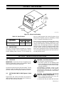
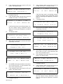
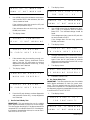
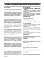
SECTION 3 – SPECIFICATIONS
16 in.
(406 mm)
9-3/4 in.
(248 mm)
13-1/8 in.
(333 mm)
SB-129 229-A
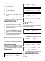
Figure 3-1. Dimensional Drawing
Table 3-1. Specifications
Input Power
Requirements
Weight
Net Ship
115 Volts AC
At 1 Ampere
44 lbs.
(20 kg)
49 lbs.
(22.2 kg)
3-1. DESCRIPTION
This unit is a microprocessor-controlled Gas Tungsten
Arc Welding (GTAW) control unit designed for use with
inverter welding power sources. This unit allows the
user to create programs that control functions of the
weld process. Programs can be run individually or linked
to run in a sequence defined by the user.
When properly connected to the welding power source,
this unit provides high frequency, preflow time, initial
current, initial slope time, final slope time, final current,
postflow time, and amperage selection of weld/peak
current for either a pulsing or nonpulsing weld current.
Pulsing controls include on/off selection, pulse time,
peak current, background current, and pulse frequency.
This unit provides a delay time for wire feed on/off con-
trol and gas flow control.
SECTION 4 – INSTALLATION OR RELOCATION
4-1. LOCATION
IMPORTANT: Read entire Section 10 regarding high-
frequency equipment location and installation require-
ments before installing this equipment.
Locate the control unit close to the work station. This will
allow torch and work weld cables to be kept as short as
possible, thereby minimizing high frequency radiation.
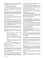
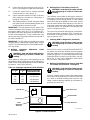
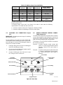
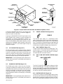
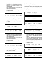
4-2. SETTING DIP SWITCH SW1 (Figures 4-1 And
5-1)
Eight-position DIP switch SW1 allows the operator to
define certain functions of the control unit. To set the po-
sitions of SW1, proceed as follows:
WARNING: ELECTRIC SHOCK can kill.
• Do not touch live electrical parts.
• Shut down control unit and welding power
source, and disconnect input power employ-
ing lockout/tagging procedures before begin-
ning this procedure.
Lockout/tagging procedures consist of pad-
locking line disconnect switch in open position,
removing fuses from fuse box, or shutting off
and red-tagging circuit breaker or other discon-
necting device.
CAUTION: ELECTROSTATIC DISCHARGE
(ESD) can damage circuit boards.
• Put on properly grounded wrist strap BE-
FORE handling circuit boards.
• Perform work only at a static-safe work area.

OM-894 Page 8
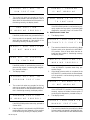
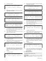
16. Loosen the front panel retaining screw (see Fig-
ure 5-1) and swing the hinged front panel down.
17. Locate DIP switch SW1 on vertically mounted
Control Board PC1 (see Figure 4-1).
18. Set the applicable positions of SW1 as desired.
SW1 settings are explained in Subsections A
through D in this section.
19. After setting position(s) of SW1, swing the hinged
front panel up into normal operating position, and
securely tighten the retaining screw.
IMPORTANT: The eight positions on DIP switch SW1
resemble miniature rocker switches. Each position has
two possible states: ON or OFF. To set a position OFF,
fully depress the end of the position nearest the side of
the DIP switch labeled OFF. To set a position ON, fully
depress the end of the position farthest from the side of
the switch labeled OFF.
IMPORTANT: The DIP switch is only read by the control
unit when power is applied after a power down, or when
a RESET is initiated through the PROGRAM/RUN/RE-
SET key switch.
A. Defining Amperage Adjustment Limits
(Positions 1 And 2)
WARNING: Read and follow safety informa-
tion at beginning of Section 4-2 before pro-
ceeding.
While welding is taking place, weld amperage can be
adjusted up or down through the use of the Remote Op-
erator Control. Amperage adjustment limits are defined
by positions 1 and 2 (see Table 4-1).
Table 4-1. Amperage Adjustment Limits Definition
Position Position
Defined Amperage
Adjustment Limit
ON ON 5 Amperes
ON
OFF
OFF
OFF
ON
OFF
10 Amperes
20 Amperes
40 Amperes
±
±
±
±
12
B. Defining Pulser Time Values (Position 3)
WARNING: Read and follow safety informa-
tion at beginning of Section 4-2 before pro-
ceeding.
Two methods are provided for defining the amount of
time spent in peak current and the amount of time spent
in background current during pulsing. The first method
allows each value to be defined as a time value, and the
second method allows direct frequency entry with the
time spent in peak current to be defined as a percentage
of the total period. The remainder of the period is then
spent in background current.
To use the first method of defining peak current/back-
ground current time, set position 3 ON. To use the sec-
ond method of defining frequency/peak time percent-
age, set position 3 OFF.
C. Selecting RUN Or Diagnostics (Position 4)
WARNING: Read and follow safety informa-
tion at beginning of Section 4-2 before pro-
ceeding.
When RUN is chosen on the PROGRAM/RUN/RESET
key switch, the control unit will either enter the program
execution mode or carry out a diagnostics routine, de-
pending on position 4. To enter the program execution
mode when RUN is chosen on the key switch, set posi-
tion 4 ON. To carry out the diagnostics routine when
RUN is chosen, set position 4 OFF.
D. Defining The Welding Power Source Used With
The Control Unit (Positions 5 Through 8)
WARNING: Read and follow safety informa-
tion at beginning of Section 4-2 before pro-
ceeding.
Positions 5-8 allow the user to define the welding power
source that is being used with the control unit (see Table
4-2). When a non-Miller welding power source is indi-
cated, a series of displays requests the information re-
quired by the control unit.
Ref. SB-132 634
Center Panel
Power
Distribution
Board PC3
Filter Board PC10
DIP Switch SW1
Control Board PC1
Line Filter FL5
Figure 4-1. Inside Front View

OM-894 Page 9
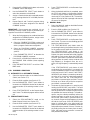
*Table 4-2. Welding Power Source Definition
Position 5 Position 6 Position 7 Position 8
Defined Welding
Power Source
ON ON ON ON Maxstar 90
ON ON ON OFF Maxstar 150 or 151
ON ON OFF ON XMT 200
ON ON OFF OFF Maxtron 300/XMT 300
ON OFF ON ON Arc Pak 350
OFF OFF OFF OFF
Non-Listed Power
Source**
*Unlisted combinations for DIP switch positions 5-8 are interpreted by the control unit as de-
fining the Maxstar 151.
**A welding power source that is not listed in the table. It must meet the following
requirements to be usable with this control unit:
1. It must be capable of doing Gas Tungsten Arc Welding (GTAW).
2. It must be capable of responding to a 0-10V control signal.
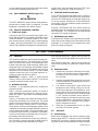
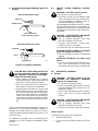
4-3. SHIELDING GAS CONNECTIONS (Figure
4-2)
IMPORTANT: Allowable pressure range for shielding
gas input is 30-50 psi.
The gas fittings on the control unit have 5/8-18 right-
hand threads. Obtain shielding gas hose of proper size,
type and length to connect from shielding gas supply to
control unit. Proceed as follows:
1. Install gas fitting onto one end of shielding gas
hose from shielding gas supply.
2. Connect hose from shielding gas supply to gas IN
fitting on rear of control unit.
3. Connect shielding gas hose from torch to gas
OUT fitting on rear of control unit.
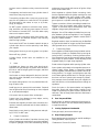
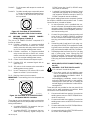
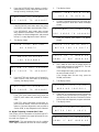
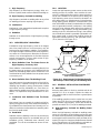
4-4. REMOTE OPERATOR CONTROL CONNEC-
TIONS (Figure 4-2)
TO OPERATOR CONTROL receptacle RC2 is used to
connect the supplied Remote Operator Control to the
control unit.To make connections, align keyway, insert
plug, and rotate threaded collar fully clockwise.
The sockets in TO OPERATOR CONTROL receptacle
RC2 function as follows:
Socket A: Provides normally closed contact with
socket C. Contact is opened when Remote
Operator Control STOP push button is
pressed.
Socket B: Provides normally open contact with socket
C. Contact is closed when Remote Opera-
tor Control DECREASE push button is
pressed.
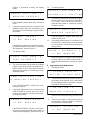
SB-129 230-A
To Operator
Control Receptacle
Strain Relief Clamp
Gas Out Fitting
Electrode Terminal
Negative Terminal
Positive/Work
Gas In Fitting
To Power Source
Receptacle
Power Switch
Terminal
Figure 4-2. Rear View

OM-894 Page 10
Socket C: Circuit common with respect to control unit
chassis.
Socket D: Provides normally open contact with socket
C. Contact is closed when Remote Opera-
tor Control START/INCREASE push but-
ton is pressed.
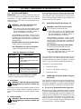
Ref. S-0446-A
DA
CB
Figure 4-3. Front View Of TO OPERATOR
CONTROL Receptacle With Socket Locations
4-5. WELDING POWER SOURCE CONNEC-
TIONS (Figures 4-2 And 4-3)
The pins of TO POWER SOURCE receptacle RC1
function as follows:
Pin A: Provides connection to program-controlled
relay contact internal to control unit; contact
makes connection with relay contact connected
to pin B to energize welding power source.
Pin B: Provides connection to program-controlled
relay contact internal to control unit; contact
makes connection with relay contact connected
to pin A to energize welding power source.
Pin D: Control circuit common with respect to pin E.
Pin E: Provides 0-10 volt command signal with re-
spect to pin D.
Pin G: 115 volts ac circuit common; also connected to
welding power source chassis.
Pin I: Up to 1.5 amperes of 115 volts ac, 60 Hz, with
respect to socket G (circuit common).
Pin K: Machine chassis (circuit common).
IMPORTANT: The remaining pins in the receptacle are
not used.
AJ
B
K
I
C
L
NH
D
M
G
E
F
Ref. S-0004-A
Figure 4-4. Front View Of TO POWER SOURCE
Receptacle With Pin Locations
These signals can be obtained by making connections
to a welding power source that provides one of the fol-
lowing combinations:
a. A suitable REMOTE 14 receptacle that pro-
vides all the necessary signals.
b. A suitable REMOTE 14 receptacle that pro-
vides all the necessary signals except the
115VAC across pins I and G (a 115VAC recep-
tacle must be available).
c. A suitable 5-socket Remote Contactor Control
receptacle that provides all the necessary sig-
nals except the 115VAC across pins I and G (a
115VAC receptacle must be available).
Each type of welding power source receptacle combina-
tion requires a different interconnection cord. To make
interconnections, proceed as follows:
1. An interconnection cord is provided that con-
nects to a Remote 14 receptacle that provides all
necessary signals. If the welding power source in
use does not have such a receptacle, obtain cor-
rect interconnecting cord.
2. Connect 14-socket plug on interconnecting cord
to the 14-pin TO POWER SOURCE receptacle
on rear of control unit as follows: align keyway, in-
sert plug, and rotate threaded collar fully clock-
wise.
3. If remaining end of cord has a 14-pin plug, con-
nect plug to the REMOTE 14 receptacle on weld-
ing power source as follows: align keyway, insert
plug, and rotate threaded collar fully clockwise.
4. If remaining end of cord has a 14-pin or 5-pin plug
and a 3-prong plug, insert 3-prong plug into
115VAC receptacle. Connect remaining plug to
applicable receptacle as follows: align keyway,
insert plug, and rotate threaded collar fully clock-
wise.
4-6. WELD INPUT/OUTPUT CONNECTIONS (Fig-
ure 4-2)
WARNING: ELECTRIC SHOCK can kill.
• Do not touch live electrical parts.
• Shut down control unit and welding power
source, and disconnect input power employ-
ing lockout/tagging procedures before in-
specting or installing.
Lockout/tagging procedures consist of pad-
locking line disconnect switch in open position,
removing fuses from fuse box, or shutting off
and red-tagging circuit breaker or other discon-
necting device.
Three terminals are provided on the rear panel of the
control unit for weld input/output connections. Make
connections to the terminals as follows:
1. Connect weld cable from positive (+) terminal on
welding power source to POSITIVE/WORK ter-
minal on control unit.
2. Connect weld cable from negative (-) terminal on
welding power source to NEGATIVE terminal on
control unit.
3. Connect weld cable from POSITIVE/WORK ter-
minal on control unit to work.
4. Connect weld cable from ELECTRODE terminal
on control unit to welding torch.

OM-894 Page 11
4-7. OPTIONAL INTERNAL WIRING CONNEC-
TIONS
WARNING: ELECTRIC SHOCK can kill.
• Do not touch live electrical parts.
• Shut down control unit and welding power
source, and disconnect input power employ-
ing lockout/tagging procedures before begin-
ning this procedure.
Lockout/tagging procedures consist of padlock-
ing line disconnect switch in open position, re-
moving fuses from fuse box, or shutting off and
red-tagging circuit breaker or other disconnect-
ing device.
CAUTION: ELECTROSTATIC DISCHARGE
(ESD) can damage circuit boards.
• Put on properly grounded wrist strap BE-
FORE handling circuit boards.
• Perform work only at a static-safe work area.
EXCESSIVE PRESSURE can break circuit
board and terminal strip.
• Use only minimal pressure and gentle move-
ment when disconnecting or connecting
leads.
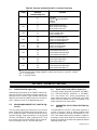
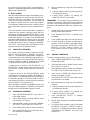
A. Wiring Connections To Pressure Terminal Strip
RC7 (Figures 4-2, 4-5, 4-6, And 4-7)
WARNING: Read and follow safety informa-
tion at beginning of Section 4-7 before pro-
ceeding.
The states of various internal relay contacts that close
and open during program execution can be used to con-
trol external devices (fixturing control is a common use).
When wired correctly, the internal relay contacts func-
tion as switches. The relay contacts are accessible
through pressure terminal strip RC7 on Interface Board
PC2 (see Figure 4-5 for typical layout of relay contacts).
The contacts are rated at 3 amperes, 120VAC each. Re-
fer to Table 4-3 for an explanation of the various contact
connections available.
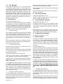
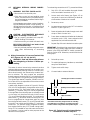
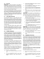
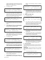
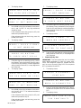
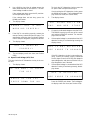
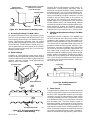
A weld profile diagram is shown in Figure 4-6. Relays
CR1 thru CR6 automatically change state at the transi-
tion time points (T
N
). Each relay resets at the end of
postflow (T
7
). However, relay CR7 can be programmed
to change state (from normally-open to normally-closed
or vice-versa) any time from the end of initial current
(T
2
), up to 25 seconds after the end of T
2
or at the end of
weld current (T
4
), whichever comes first. Relay CR7 can
then be programmed to change state again any time
from the end of weld current (T
4
), up to 25 seconds after
the end of T
4
or until the end of postflow (T
7
), whichever
comes first. The operator simply programs the delay
time required before relay CR7 should change state.
Relay CR7 is intended for use with external wire feed-
ers; however, it can be used for other purposes at the
discretion of the operator.
To make wiring connections to RC7, proceed as follows:
1. Strip 1/2 in. (13 mm) insulation from ends of leads
to be connected to terminals on RC7.
2. Loosen strain relief clamp (see Figure 4-2) on
rear panel of control unit sufficiently to allow de-
sired number of leads to be inserted.
3. Remove top cover.
4. Locate pressure terminal strip RC7 on Interface
Board PC2 (see Figure 4-7).
5. Route stripped ends of leads through strain relief
clamp on back of control unit.
6. Press down on slotted end of white tab for desired
connection point (1-24), insert stripped end of
applicable lead, and release white tab.
7. Repeat Step 6 for each desired connection point.
IMPORTANT: If making wiring connections to pressure
terminal strip RC3 (used to signal the end of a weld se-
quence in the SEMI-AUTOMATIC mode), proceed di-
rectly to Section 4-7B. Otherwise, continue with the fol-
lowing steps.
8. Reinstall top cover.
9. To avoid high frequency interference, route leads
away from weld cables.
10. Tighten strain relief clamp.
11. Connect leads to external devices.
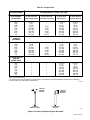
*CR
Normally Open Contacts Connection
Normally Closed Contacts Connection
Wiper Connection
*The related control relay energizes when its controlling
event takes place (see Table 4-3). For instance, the Start
Postflow contacts change states when postflow begins.
S-0650
Figure 4-5. Typical Layout For Internal Relays
Connected To Terminal Strip RC7

OM-894 Page 12
S-0844
CR1 Reset
CR2 Reset
CR3 Reset
CR4 Reset
CR5 Reset
CR6 Reset
CR7 Reset
CR1
CR2
CR5
CR6
CR7
CR3
CR4
CR7
Preflow
Initial
Current
Initial
Slope
Weld/Peak
Current
Final
Slope
Final
Current
Postflow
T
1
T
2
T
3
T
4
T
5
T
6
T
7
Background
Current (when
pulsing
Relay Contacts
PTD 0 to 25 sec. or end T
7
(whichever comes first, wire feed delay)
PTD 0 to
25 sec.
or end T
4
(whichever comes first)
T
N
= Time
PTD = Programmed Time Delay
Figure 4-6. Weld Profile Diagram
B. Wiring Connections To Pressure Terminal Strip
RC3 (Figures 4-2 And 4-7)
WARNING: Read and follow safety informa-
tion at beginning of Section 4-7 before pro-
ceeding.
The two terminals in pressure terminal strip RC3 are
used in the SEMI-AUTOMATIC Mode to signal the end
of a weld sequence. This is done by closing contacts
that are wired to pressure terminal strip RC3 on Inter-
face Board PC2. To make the needed wiring connec-
tions, proceed as follows:
1. Strip 1/2 in. (13 mm) insulation from ends of
leads to be connected to terminals on RC3.
2. Loosen strain relief clamp on rear panel of control
unit (see Figure 4-2) sufficiently to allow leads to
be inserted.
3. Remove top cover (if applicable).
4. Locate pressure terminal strip RC3 on Interface
Board PC2 (see Figure 4-7).
5. Route stripped ends of leads through strain relief
clamp on back of control unit.
6. Press down on slotted end of white tab for one of
the two connection points, insert stripped end of
applicable lead, and release white tab.
7. Repeat Step 6 for other connection point.
8. Reinstall top cover.
9. To avoid high frequency interference, route leads
away from weld cables.
10. Tighten strain relief clamp.
11. Connect leads from RC3 to relay. If applicable,
connect leads from RC7 to external devices.
Ref. SB-132 634
Fuse F1 Pressure Terminal
Strip RC3
Relay Mounting
Panel
Pressure Terminal
Strip RC7
Interface
Board PC2
Figure 4-7. Inside Top View

OM-894 Page 13
Table 4-3. Pressure Terminal Strip RC7 Connection Functions
Maximum allowable voltage between collector and common is +40 VDC, 100MA
Pressure
Terminal Strip RC7
Function
1
2
3
Common
Signal Synchronized With
+24VDC
4
5
6
Wire Feed Contact N.O.
Wire Feed Contact Wiper
Wire Feed Contact N.C.
7
8
9
Start Postflow N.O.
Start Postflow Wiper
Start Postflow N.C.
10
11
12
Start Final Amperage N.O.
Start Final Amperage Wiper
Start Final Amperage N.C.
13
14
15
Start Final Slope N.O.
Start Final Slope Wiper
Start Final Slope N.C.
16
17
18
Start Weld Amperage N.O.
Start Weld Ameprage Wiper
Start Weld Amperage N.C.
19
20
21
Start Initial Slope N.O.
Start Initial Slope Wiper
Start Initial Slope N.C.
22
23
24
Start Initial Amperage N.O.
Start Initial Amperage Wiper
Start Initial Amperage N.C.
* Open collector – transistor ON during peak current.
N.O. = normally open
N.C. = normally closed
♦
♦
♦
Pulses*
Connection On
Relay
CR7
CR6
CR5
CR4
CR3
CR2
CR1
SECTION 5 – OPERATOR CONTROLS
5-1. POWER SWITCH (Figure 4-2)
Depressing the ON portion of the POWER switch ener-
gizes the control unit and makes it ready to operate. De-
pressing the OFF portion of the POWER switch shuts
down the unit. When the POWER switch is in the ON po-
sition, a display is seen in the digital display area.
5-2. PROGRAM/RUN/RESET KEY SWITCH (Fig-
ure 5-1)
This key switch places the control unit in one of three
states. Selecting PROGRAM allows the operator to en-
ter or modify a program. Selecting RUN locks out any
program changes. Program execution can be carried
out from PROGRAM or RUN. Selecting RESET and
then returning to RUN or PROGRAM has the same ef-
fect as turning the unit OFF and then ON again.
5-3. MODE SELECTOR SWITCH (Figure 5-1)
This switch selects the mode of operation: AUTOMAT-
IC-1, SEMI-AUTOMATIC, MANUAL, or AUTOMAT-
IC-2, (see Section 6-3). During programming, this
switch allows programs to be entered into each mode.
When the unit is placed in RUN, it will operate in the
mode selected on the mode switch.
5-4. PARAMETER SELECT PUSH BUTTON (Fig-
ure 5-1)
The PARAMETER SELECT push button performs a
number of functions. When a display contains more
than one parameter, pressing the PARAMETER SE-
LECT push button selects each parameter in sequence.
Pressing the push button while the last parameter in a
display is selected will de-select that parameter without
selecting another one.

OM-894 Page 14
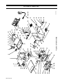
SB-129 229-A
ST-149 839
Front Panel
Retaining Screw
Weld Amperage
Display
Gas Flow
Meter
Digital Display
Up
Push Button
Down
Push Button
Purge
Push Button
Parameter Select
Push Button
Mode Selector
Switch
Program/Run/Reset
Key Switch
Remote Operator
Control
Stop
Push Button
Start/Increase
Push Button
Decrease
Push Button
4-Pin Plug
Figure 5-1. Control Unit Front Panel View And Remote Operator Control
Pressing the PARAMETER SELECT push button while
the PULSE ON/OFF display is shown will toggle be-
tween one option and the other.
Pressing the PARAMETER SELECT push button in the
RUN condition (see Section 6-2) will increment the
PROGRAM #. Pressing PARAMETER SELECT re-
peatedly will bring up programs one through ten, after
which the PROGRAM “LINK” MODE display is shown
and then the ”COMBINE” MODE display. Pressing the
PARAMETER SELECT push button again brings up
program one again.
5-5. UP PUSH BUTTON (Figure 5-1)
The UP push button carries out two functions. Pressing
the UP push button while a parameter is selected will in-
crease the parameter value (press and hold the push
button to increase the value rapidly). Pressing the UP
push button without a parameter being selected will
show the previous display in the display sequence.
IMPORTANT: To zero a parameter value, select the pa-
rameter and press the UP and DOWN push buttons at
the same time.
5-6. DOWN PUSH BUTTON (Figure 5-1)
The DOWN push button carries out two functions.
Pressing the DOWN push button while a parameter is
selected will decrease the parameter value (press and
hold the push button to decrease the value rapidly).
Pressing the DOWN push button without a parameter
being selected will show the next display in the display
sequence.
IMPORTANT: To zero a parameter value, select the pa-
rameter and press the UP and DOWN push buttons at
the same time.
5-7. PURGE PUSH BUTTON (Figure 5-1)
PURGE
The PURGE push button is a momentary-contact
switch. Pressing the PURGE push button energizes the
gas solenoid and purges the gas line of the welding
torch. The PURGE push button allows the gas flow to be
adjusted without energizing the weld circuitry. PURGE
is active only in the Run condition (see Section 6-2).
5-8. GAS CONTROL (Figure 5-1)
The gas control adjusts the flow of shielding gas. Turn-
ing the control in a clockwise direction decreases the
flow of shielding gas. Turning the control in a counter-
clockwise direction increases the flow.
5-9. GAS FLOW RATE DIGITAL METER (Figure
5-1)
GAS FLOW RATE
(CFH)
The GAS FLOW RATE digital meter indicates the flow
rate of the shielding gas. The meter is calibrated in cubic
feet per hour and has a range of 0-50 cubic feet per hour
with Argon shielding gas. If gas flow rate exceeds 50 cu-
bic feet per second, the display reads OL.
5-10. DIGITAL DISPLAY (Figure 5-1)
The two line by twenty character digital display allows
the user to enter values and to read values once they are
entered. When a program is performed (either in RUN or
DRY RUN), weld sequence displays are shown as they
Page is loading ...
Page is loading ...
Page is loading ...
Page is loading ...
Page is loading ...
Page is loading ...
Page is loading ...
Page is loading ...
Page is loading ...
Page is loading ...
Page is loading ...
Page is loading ...
Page is loading ...
Page is loading ...
Page is loading ...
Page is loading ...
Page is loading ...
Page is loading ...
Page is loading ...
Page is loading ...
Page is loading ...
Page is loading ...
Page is loading ...
Page is loading ...
Page is loading ...
Page is loading ...
Page is loading ...
Page is loading ...
Page is loading ...
Page is loading ...
Page is loading ...
Page is loading ...
Page is loading ...
Page is loading ...
Page is loading ...
Page is loading ...
Page is loading ...
Page is loading ...
Page is loading ...
Page is loading ...
-
 1
1
-
 2
2
-
 3
3
-
 4
4
-
 5
5
-
 6
6
-
 7
7
-
 8
8
-
 9
9
-
 10
10
-
 11
11
-
 12
12
-
 13
13
-
 14
14
-
 15
15
-
 16
16
-
 17
17
-
 18
18
-
 19
19
-
 20
20
-
 21
21
-
 22
22
-
 23
23
-
 24
24
-
 25
25
-
 26
26
-
 27
27
-
 28
28
-
 29
29
-
 30
30
-
 31
31
-
 32
32
-
 33
33
-
 34
34
-
 35
35
-
 36
36
-
 37
37
-
 38
38
-
 39
39
-
 40
40
-
 41
41
-
 42
42
-
 43
43
-
 44
44
-
 45
45
-
 46
46
-
 47
47
-
 48
48
-
 49
49
-
 50
50
-
 51
51
-
 52
52
-
 53
53
-
 54
54
-
 55
55
-
 56
56
-
 57
57
-
 58
58
-
 59
59
-
 60
60


Miller KE607495 Owner's manual
- Category
- Welding System
- Type
- Owner's manual
- This manual is also suitable for
Ask a question and I''ll find the answer in the document
Finding information in a document is now easier with AI
Related papers
-
Miller JG070373 Owner's manual
-
-
-
-
Miller PS-100 Owner's manual
-
-
-
-
-