Page is loading ...

Quick Reference 931665A © 2019, CyberData Corporation, ALL RIGHTS RESERVED© 2019, CyberData Corporation, ALL RIGHTS RESERVED 931665A Quick Reference
Typical System Installation
Getting Started
• Download the Operations Guide PDF file, from the Downloads tab at the following webpage:
https://www.cyberdata.net/products/01147
8
• Create a plan for the locations of your devices.
• WARNING: This product should be installed by a licensed electrician according to all local electrical and building codes.
• WARNING: To prevent injury, this apparatus must be securely attached to the floor/wall in accordance with the installation
instructions.
• WARNING: The PoE connector is intended for intra-building connections only and does not route to the outside plant.
• WARNING: This enclosure is not rated for any AC voltages!
Parts
Parameter Factory Default Setting
IP Addressing DHCP
IP Address
a
a. Default if there is not a DHCP server present.
10.10.10.10
Web Access Username admin
Web Access Password admin
Subnet Mask
a
255.0.0.0
Default Gateway
a
10.0.0.1
802.3af Compliant Ethernet Switch
Endpoint IP Phone IP PBX ServerEndpoint Endpoint
*More installation and mounting
options are available in the
Operations Guide.
Accessory Kit Security Torx MS
Accessory Kit
Carriage Bolt Bolts
Carriage Bolt Nuts
Carriage Bolt Washers
Mounting Component
(1) Assembly
(1) 1/2-inch EMT
compression
connector with extra
sealing locknut
(1) 531085* Hole
plug assembly
Optional Accessories
Security Torx Key
The IP Endpoint Company
Installation Quick Reference
SIP Outdoor Video Intercom with RFID
Secure Access Control Endpoint
011478
Gooseneck Mounting
Contacting CyberData
Conduit
Ground Wire
Network Cable
1/2" EMT
Compression
Connector
1/2" EMT
Anchor Screw
1/4"
1/4" Concrete
(Sold Separately)
Weather Shroud
(Sold Separately)
Weather Shroud
Wall Anchor
Backbox
Torx Key
Torx Security Screw
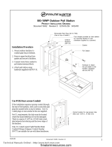
Faceplate Mounting
Torx Key
SIP Outdoor Video Intercom
RFID Access Control Endpoint
(3 Sets Included)
Washer & Nut
Gooseneck
Through Side Conduit Hole
Network and Ground Wires in
Cable & Wire
Create Service Loop
Cable & Wire
Create Service Loop
Apply RTV Silicone Sealant Around Mounting Holes and
Backside Perimeter of Backbox and Weather Shroud
Carriage Bolt, Washer & Nut
Apply RTV Silicone Sealant Around Mounting Holes and
Backside Perimeter of Backbox and Weather Shroud
with
Sealing Locknut
(Sold Separately)
Torx Security Screw
Faceplate Mounting
Remove Hole Plug Assembly then
Install It onto Rear Conduit Hole
*
*
J1
J1
to J1
to J1
*More installation and mounting information
is illustrated in the Operations Guide.
Sales: (831) 373-2601 ext. 334
Support: 831-373-2601 ext. 333
Support Website: http://support.cyberdata.net/
RMA Department: (831) 373-2601 ext. 136
RMA Email: [email protected]
RMA Status: http://support.cyberdata.net/
Warranty Information: http://support.cyberdata.net/
Corporate Headquarters
CyberData Corporation
3 Justin Court
Monterey, CA 93940, USA
Phone: 831-373-2601
Fax: 831-373-4193
http://www.cyberdata.net/

© 2019, CyberData Corporation, ALL RIGHTS RESERVED 931665A Quick Reference Quick Reference 931665A © 2019, CyberData Corporation, ALL RIGHTS RESERVED
Terminal Block Connections
RTFM Button
7.480 [190.0]
5.118 [130.0]
2.265 [57.5]
Dimensions are in Inches [Millimeter]
RFID
Features Dimensions (Front and Side View)
Green LEDRed LED Buzzer
0.25"
Terminal Block
Wire (IN)
can accept 16 AWG wire
1
8
Alternate Power Input:
1 = +8 to +12VDC @ 1000mA Regulated Power Supply*
2 = Power Ground*
Relay Contact:
(1 A at 30 VDC for continuous loads)
3 = Relay Common
4 = Relay Normally Open Contact
5 = Sense Input
6 = Sense Ground
7 = Remote Switch "A"
8 = Remote Switch "B"
*Contacts 1 and 2 on the terminal block are only for
powering the device from a non-PoE 12VDC power
source as an alternative to Network PoE power. Use of
these contacts for any other purpose will damage the
device and void the product warranty.
3
4
Use a 3.17 mm (1/8-inch) flat blade
screwdriver for the terminal block screws
RTFM button (SW1)
When the device is operational and linked to a
network, you can use the Reset Test Function
Management (RTFM) button (SW1 [see pic-
ture]) to restore the device to the factory
default settings.
To restore the device to factory default
settings:
• Press and hold the RTFM button for
longer than five seconds.
Note The device will use DHCP to obtain
the new IP address (DHCP-assigned
address or default to 10.10.10.10 if a
DHCP server is not present).
Dimensions (Rear View and Mounting Holes)
Wall Mounting with Ground Cable and Network Cable Installation
Ø0.875 [Ø22]
7.480 [190.0]
3.181 [80.8]
3.181 [80.8]
3.399 [86.3]
4.580 [116.3]
5.118 [130.0]
3.380 [85.9]
7.008 [178.0]
0.559 [14.2]
3.380 [85.9]
1/2" EMT Compression Connector
Conduit Hole Fits
1/4" Screws
Mounting Holes Fits
Mounting Holes
Flange Flush Mount
#6-32 Threads
Faceplate Mounting Holes
0.269 [6.8]
Hex Nut Socket Size 5/16” or 8mm
Ground Lug Fits Size 8 Ring Terminal
1.695 [43.1]
0.730 [18.5]
Dimensions are in Inches [Millimeter]; Projection: Third Angle.
Ø0.875 [Ø22]
Ø0.280 [Ø7]
Side Conduit Hole
Ground Wire
Network Cable
Anchor Screw
1/4"
1/4" Concrete
(Sold Separately)
Weather Shroud
Wall Anchor
Torx Security Screw
Faceplate Mounting
Torx Key
SIP Outdoor Video Intercom
RFID Access Control Endpoint
Ground Lug
Ground Wire to
Through Rear Conduit Hole
Network and Ground Wires in
Backbox
Apply RTV Silicone Sealant Around Mounting Holes and
Backside Perimeter of Backbox and Weather Shroud
*
J1
to J1
Backbox Mounting Holes Fits 1/4"
Concrete Anchor and Screw; Gound Lug Fits Size 8 Ring Terminal.
(All Mounting Hardwares and Cable Assemblies are Not Provided)
Note: For flush mount installations, purchase the 011442 Flush
Mount Kit, 2x (sold separately). For more information, go to:
https://www.cyberdata.net/products/011442
Note: To mount the device, use methods
compliant with local electrical codes.
Note: More installation and mounting information
is illustrated in the Operations Guide.
Caution
Equipment Hazard: Do not use an electric or power screwdriver to fasten the face plate and PCB assembly to
the gang box. To prevent over-torque damage to the gasket, do not apply more than 10 inch-pounds force.
Over-torquing will cause the gasket to tear, risk moisture intrusion, and effectively void the manufacturer's
warranty.
GENERAL ALERT
/