Page is loading ...

For questions or help with this product contact Tech Support at (570) 546-9663 or techsupport@grizzly.com
MODEL T26748
PNEUMATIC
GREASE PUMP
INSTRUCTIONS
COPYRIGHT © AUGUST, 2014 BY GRIZZLY INDUSTRIAL, INC.
NO PORTION OF THIS MANUAL MAY BE REPRODUCED IN ANY SHAPE
OR FORM WITHOUT THE WRITTEN APPROVAL OF GRIZZLY INDUSTRIAL, INC.
#MN16583 PRINTED IN CHINA
Inventory
EYE INJURY HAZARD!
Always wear safety glasses
during use to prevent
serious personal injury.
INJURY HAZARD!
When servicing, always dis-
connect tool from air to pre-
vent unexpected operation.
120 PSI
MAX AIR PRESSURE!
Exceeding this PSI may
result in injury/tool damage.
Pressure Ratio .............................................. 50:1
Air Inlet Working Pressure .................9 0 –115 PSI
Max. Air Pressure ....................................120 PSI
Max. Oil Outlet Pressure ...................... 5800 PSI
Max. Flow Rate ..................................... .22 GPM
Grease Outlet ................................................M14
High-Pressure Hose ...............................M14 x 8'
Volume........................................3 Gallons (12 L)
Types of Grease ............................. NLGI #1, 2, 3
Specifications
Introduction
The Model T26748 Pneumatic Grease Pump is a
high-pressure grease delivery system designed to
be completely portable and operate hands-free.
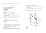
Description Qty
A. High-Pressure Hose ................................... 1
B. Grease Gun ................................................ 1
C. Pneumatic Pump (Installed) ....................... 1
D. Grease Drum .............................................. 1
Figure 1. Model T26748 inventory components.
A
B
C
D
Assembly
Tools Required Qty
Open-End Wrench 17mm ............................2 Ea.
To assemble grease pump:
1. Screw high-pressure hose onto grease out-
let on pneumatic pump and tighten securely
(see Figure 2).
Figure 2. High-pressure hose attached to pump.
High-
Pressure
Hose
Grease Outlet

-2-
T26748 Pneumatic Grease Pump (Mfd. 5/14)
2. Screw grease gun fitting onto other end of
high-pressure hose and tighten securely (see
Figure 3).
3. Attach grease pump to compressed air
source. To improve tool lifespan and avoid
contaminating grease with water from air
supply lines, use a filter/lubricator/regulator
setup, as shown in Figure 4.
Filling
1. Remove lid assembly from grease drum.
Tip: When removing lid assembly from drum,
tilt it slightly to one side. This relieves suction
and allows assembly to slide out more easily.
2. Fill drum with bulk grease (see Specifications
on Page 1), ensuring that no air pockets
remain.
3. Slide lid assembly back into grease drum,
making sure follower plate is seated evenly
against side of drum body to prevent air pock-
ets from forming (see Figure 5).
4. Once lid assembly is fully seated, secure with
latches.
Figure 3. High-pressure hose attached to grease
gun.
High-Pressure Hose
Grease Gun
Quick
Connector
Quick
Coupler
Air Hose
Quick
Coupler
Quick
Connector
Lubricator
Filter
Regulator
Your
Tool
Air
Compressor
Figure 4. Example of a filter/lubricator/regulator
setup.
Do not allow pneumatic pump to run dry.
This can cause pump to overheat, which
can quickly damage the machine. This type
of damage is considered to be neglect and
will not be covered under warranty.
Figure 5. Follower plate seated evenly against
drum body.
Follower Plate
Lid Assembly

T26748 Pneumatic Grease Pump (Mfd. 5/14)
-3-
Maintenance
Clean and lubricate the pneumatic pump and
grease gun on a regular basis to ensure safe and
efficient operation. When not in use, the high-
pressure hose and grease gun should be discon-
nected from the grease pump. The grease pump
should be stored away from direct heat, in a dry
area with good ventilation.
Cleaning
After each use, hold down grease gun trigger to
ensure that all grease has been expelled. Then
remove tip of grease gun and wipe down all parts.
Lubrication
Weekly, put 2 oz. of air-pump lubricant in the air
inlet hole (see Figure 7).
Connect pneumatic pump to air source and allow
to run for several minutes until internal parts are
fully lubricated.
Figure 7. Location of air inlet hole where air-
pump lubricant is added.
1. Connect grease pump to compressed air
regulated at 90–115 PSI (see Figure 6).
Note: To alter pressure setting on pump, pull
regulator cap out. Turn left to decrease pres-
sure; turn right to increase pressure. Push
cap back in when finished.
2. Squeeze grease gun trigger once or twice to
expel any contaminants or old grease. Allow
just enough grease to escape to ensure it is
clean, then wipe off with rag.
3. Insert tip of grease gun into fitting to be lubri-
cated, then squeeze trigger to inject grease.
4. Once desired amount of grease has been
injected into fitting, release trigger.
5. When finished, disconnect compressed air
source.
Do not perform maintenance on pump until
it has been disconnected from air source.
Exposure to air under high pressure can
cause serious personal injury.
Do not disconnect grease gun or high-
pressure hose while grease pump is con-
nected to air source. Serious personal
injury can result otherwise.
Operation
Air Inlet Hole
Figure 6. Primary components of pneumatic
pump.
Air Hose
Fitting
Regulator
Pressure
Gauge

-4-
T26748 Pneumatic Grease Pump (Mfd. 5/14)
Troubleshooting
Review the troubleshooting and procedures in this section if a problem develops with your machine. If you
need replacement parts or additional help with a procedure, call our Technical Support at (570) 546-9663.
Note: Please gather the serial number and manufacture date of your machine before calling.
Symptom Possible Cause Possible Solution
Grease not pumping
through gun.
1. Blockage in grease gun.
2. Air pocket in grease drum.
3. Not enough grease in drum.
1. Disassemble and clean gun assembly.
2. Remove lid assembly, then slowly re-insert; keep
follower plate square to grease drum.
3. Refill drum with more grease.
Grease pumping
slowly from gun.
1. Grease is too heavy (thick).
2. Insufficient air pressure.
3. Pump/air source leaks.
4. Obstruction in grease gun.
5. Obstruction between check valve and air
inlet valve.
1. Add 8–10 oz. of SAE 40 or similar oil to grease drum;
use lighter weight grease.
2. Check air source for correct psi: 90–115.
3. Tighten fittings.
4. Disassemble grease gun and clean thoroughly.
5. Disassemble grease inlet valve and clean thoroughly.
Grease leaking at
outlet/hose connection.
1. Loose hose connection. 1. Tighten hose on outlet connection.
Grease leaking at
gun/hose connection.
1. Loose grease gun connection. 1. Tighten grease gun fitting on hose.
Grease leaking from
swivel connector on
grease gun handle.
1. Blown O-ring. 1. Replace O-ring.
Pump continues to
run after grease gun
trigger is released.
1. Grease drum is empty.
2. Leak in hose/gun.
3. Valve not closing due to dirt or wear.
1. Refill drum with grease.
2. Check all connections; tighten or repair.
3. Disassemble and clean valves.

T26748 Pneumatic Grease Pump (Mfd. 5/14)
-5-
Parts
Please Note: We do our best to stock replacement parts whenever possible, but we cannot guarantee that all parts shown here
are available for purchase. Call (800) 523-4777 or visit our online parts store at www.grizzly.com to check for availability.
REF PART # DESCRIPTION REF PART # DESCRIPTION
1 PT26748001 AIR TUBE 31 PT26748031 CONNECTING ROD
2 PT26748002 COVER 32 PT26748032 VALVE CONNECTOR
3 PT26748003 PLATE SPRING 33 PT26748033 STEEL BALL 6MM
4 PT26748004 POSITION PLATE 34 PT26748034 COMPRESSION SPRING
5 PT26748005 SLIDER 35 PT26748035 SPRING SEAT
6 PT26748006 GASKET 36 PT26748036 PISTON
7 PT26748007 SOFT GASKET 37 PT26748037 O-RING 14 X 2.65
8 PT26748008 AIR MOTOR SHELL 38 PT26748038 STEEL BALL 6MM
9 PT26748009 AIR MOTOR COVER 39 PT26748039 COMPRESSION SPRING
10 PT26748010 ELBOW 90 DEGREE 40 PT26748040 CONNECTING ROD
11 PT26748011 COMPRESSION NUT M16-1.5 41 PT26748041 ADJUSTMENT NUT
12 PT26748012 AIR TUBE 42 PT26748042 CONNECTING ROD
13 PT26748013 MUFFLER 43 PT26748043 PISTON ROD
14 PT26748014 TRIP SHOE GUIDE 44 PT26748044 SLEEVE
15 PT26748015 SPRING SEAT 45 PT26748045 PISTON
16 PT26748016 COMPRESSION SPRING 46 PT26748046 FENDER WASHER 10MM
17 PT26748017 SPRING SHELL 47 PT26748047 HEX NUT M10-1
18 PT26748018 GASKET 22MM 48 PT26748048 LID
19 PT26748019 VALVE SEAL 12MM 49 PT26748049 DRUM
20 PT26748020 CONNECTOR 50 PT26748050 WHEEL
21 PT26748021 CONNECTING TUBE 51 PT26748051 EXT RETAINING RING 12MM
22 PT26748022 PISTON SHELL 52 PT26748052 BASE
23 PT26748023 VALVE SEAT 53 PT26748053 GRIZZLY GREEN TOUCH-UP PAINT
24 PT26748024 SUCTION TUBE 54 PT26748054 MACHINE ID LABEL
25 PT26748025 HEX NUT M6-1 55 PT26748055 GRIZZLY.COM LABEL
26 PT26748026 DOCK WASHER 6MM 56 PT26748056 EXPLOSION HAZARD LABEL
27 PT26748027 RUBBER WASHER 6MM 60 PT26748060 GREASE GUN
28 PT26748028 VALVE RING 61 PT26748061 HIGH PRESSURE HOSE 7500-PSI
29 PT26748029 VALVE 62 PT26748062 HANDLE
30 PT26748030 SEAL
1
2
3
4
5
6
7
8
9
10
11
12
13
14
15
16
17
18
19
20
21
22
23
24
25
26
27
28
29
30
31
32
33
34
35
36
37
38
39
40
41
42
43
44
45
46
47
48
50
51
52
49
53
55
60
61
62

-6-
T26748 Pneumatic Grease Pump (Mfd. 5/14)
/