3M Cold Shrink QS-III Splice Kit 5525A-750-CU, 25/28 kV, 750 kcmil, 1/case Operating instructions
- Category
- Signal cables
- Type
- Operating instructions
This manual is also suitable for
- Cold Shrink QS-III Splice Kit 5525A, 25/28 kV, 250-750 kcmil (120-325 mm2), 1/case
- Cold Shrink QS-III Splice Kit 5525A-250-AL, 250 kcmil, 1 per case
- Cold Shrink QS-III Splice Kit 5525A-250-CU, 25/28 kV, Standard, 1/case
- Cold Shrink QS-III Splice Kit 5525A-350-AL, 350 kcmil, 1 per case
- Cold Shrink QS-III Splice Kit 5525A-350-CU, 25/28 kV, 350 kcmil, 1/case
- Cold Shrink QS-III Splice Kit 5525A-500-AL, 25/28 kV, 500 kcmil, 1/case
- Cold Shrink QS-III Splice Kit 5525A-500-CU, Tape, Wire, Unishield, 25/28 kV, Standard, 1 per case
- Cold Shrink QS-III Splice Kit 5525A-750-AL, 25/28 kV, Standard, 1/case

3M
™
Cold Shrink Splice Kit QS-III
5525A
for UniShield
®
, Wire Shielded, Longitudinally Corrugated (LC),
and Tape Shielded (Ribbon Shielded) Cable or Transitions to
Concentric Neutral (CN)/Jacketed Concentric Neutral (JCN) Cables
Instructions
IEEE Std. 404
25/28 kV Class
200 kV BIL
CAUTION
Working around energized systems may cause serious injury or death. Installation should
be performed by personnel familiar with good safety practice in handling electrical
equipment. De-energize and ground all electrical systems before installing product.
Kit Selection Table
Kit Number Cable Insulation O.D. Range Conductor Size Range
5525A
1.07"–1.70"
(27,2–43,2 mm)
250–750 kcmil*
(120–325 mm
2
)
* Splices (including size transitions) can be made to smaller or larger conductors (but larger conductors may require special neutral
handling), provided both cables are within the Insulation O.D. Range and the connector meets the dimensional requirements
shownbelow.
Connector Dimensional Requirements
Minimum Inches (mm) Maximum Inches (mm)
Outside Diameter 0.75" (19,1 mm) 1.70" (43,2 mm)
Length
Aluminum (Al/Cu) Compression
—
5.75" (146 mm)
Length
Copper Compression and 3M
™
Shearbolt Connector
QCI 350-750
—
6.69" (170 mm)
March2011
78-8125-9898-1-C 3

2 78-8125-9898-1-C
1.0 Kit Contents
a. 3M
™
ColdShrinkSpliceBody5457A(1ea.)
b. ColdShrinkJacketingTube(1ea.)
c. ColdShrinkAdapterTube(1ea.)
d. ShieldingSleeve,1/3NeutralMaximum(1ea.)
e. GroundStrap(1ea.)
f. ConstantForceSpringGroundConnectors(5ea.)
g. RedCompoundTubes(non-siliconegrease)(2ea.)
h. Scotch
®
MasticSealingStrips2230,6"length(6ea.)
i. Scotch
®
RubberMasticTape2228Rolls,2"x36"(2ea.)
j. CopperFoilTape,1/2"x10"(2ea.)
k. 3M
™
CableCleaningPadsCC-3(1ea.)
l. CablePreparationTemplate(1ea.)
m.InstructionBooklet(1ea.)
Note: Donotuseknivestoopenplasticbags.
Note: Connectornotshown,butifincluded,itisindicatedonthepackaginglabel.
Note: Item“C,”ColdShrinkAdapterTube,maynotbeincludedinallkits.

78-8125-9898-1-C 3
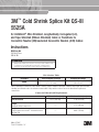
2.0 Prepare Cables
2.1 For Tape, LC, Wire Shield or UniShield
®
Cable:
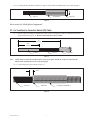
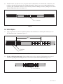
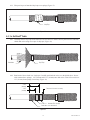
2.1.1 Preparecablesaccordingtostandardprocedures.Refertotemplateprovidedorillustrationbelowfor
properdimensions.(Figure1).
8 1/2"
(216 mm)
15"
(381 mm)
3 1/2"
(89 mm)
Cable Jacket
Metallic
Shield
Semi-con
Insulation
8 1/2"
(216 mm)
15"
(381 mm)
3 1/2"
(89 mm)
Cable Jacket
Wire Shield
Semi-con
Insulation
8 1/2"
(216 mm)
15"
(381 mm)
Insulation
Shield Wires
3 1/2"
(89 mm)
Tape & LC Shielded Cables
Wire Shielded Cable
UniShield
®
Cable
Figure1
Note: CablesmustbewithintheinsulationO.D.rangeofthesplicekitandtheconnectormustmeetthe
dimensionalrequirementsshownonthefrontpage.

4 78-8125-9898-1-C
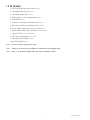
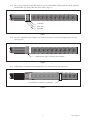
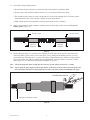
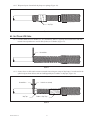
2.1.2 For Tape shield and LC shield: Secureendofeachmetallicshieldwithacoppertapestrip.
For Wire shield and UniShield
®
:Carefullybendshieldwiresbackovercablejacketsandtemporarily
securewithvinyltape.(Figure2).
Tape & LC Shielded Cables
Wire Shielded Cable
UniShield
®
Cable
Foil Tape
Semi-con
Semi-con
Metallic Shield
Cable Jacket
Semi-con
Cable Jacket
Vinyl Tape Shield Wires
Cable Jacket
Vinyl Tape Shield Wires
Vinyl TapeNeutral Wires
Figure2
Gotosection3.0“ParkSpliceComponents.”ifnottransitionsplicingtoJCNorCNcable.
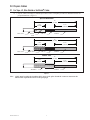
2.2 For Transitions to Jacketed Concentric Neutral (JCN) Cable:
2.2.1 Preparecablesaccordingtostandardprocedures.Refertotemplateprovidedorillustrationbelowfor
properdimensions(Figure3).
8 1/2"
(216 mm)
15"
(381 mm)
Neutral Wires
Semi-con
Insulation
8 1/2"
(216 mm)
15"
(381 mm)
Neutral Wires
Semi-con
Insulation
Concentric Neutral (CN)
Jacketed Concentric Neutral (JCN)
Figure3
Note: CablesmustbewithintheinsulationO.D.rangeofthesplicekitandtheconnectormustmeetthe
dimensionalrequirementsshownonthefrontpage.

78-8125-9898-1-C 5
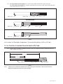
2.2.2 Carefullybendneutralwiresbackoveredgeofcablejacketandtemporarilysecurewithvinyltape.
Tape & LC Shielded Cables
Wire Shielded Cable
UniShield
®
Cable
Foil Tape
Semi-con
Semi-con
Metallic Shield
Cable Jacket
Semi-con
Cable Jacket
Vinyl Tape Shield Wires
Cable Jacket
Vinyl Tape Shield Wires
Vinyl TapeNeutral Wires
Figure4
Gotosection3.0“ParkSpliceComponents.”
2.3 For Transitions to Concentric Neutral (CN) Cable:
2.3.1 Preparecablesaccordingtostandardprocedures.Refertotemplateprovidedorillustrationbelowfor
properdimensions(Figure5).Do not cut neutral wires on CN cables.
8 1/2"
(216 mm)
15"
(381 mm)
Neutral Wires
Semi-con
Insulation
8 1/2"
(216 mm)
15"
(381 mm)
Neutral Wires
Semi-con
Insulation
Concentric Neutral (CN)
Jacketed Concentric Neutral (JCN)
Figure5
Note: CablesmustbewithintheinsulationO.D.rangeofthesplicekitandtheconnectormustmeetthe
dimensionalrequirementsshownonthefrontpage.
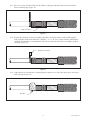
2.3.2 Cleancablesemi-conasshown(Figure6).
Binder Wire
Folded Back Neutral Wires
Semi-Con
Clean
Figure6

6 78-8125-9898-1-C
2.3.3 Placeastripofmasticaroundcablesemi-connexttoneutralbinder.Foldneutralsintomasticandplace
anotherbinderwireontheothersideofthemastic(Figure7).
Binder Wire
Mastic Strip
Binder Wire
Figure7
2.3.4 Wraptwoadditionalstripsofmasticoverthefirstoneandcoverwithtwohalflappedlayersofvinyl
tape(Figure8).
2 additional mastic strips covered with 2 layers vinyl tape
Figure8
2.3.5 Foldneutralsovermasticsealandtemporarilysecureendswithvinyltape(Figure9).
Secure folded-back neutral wires with vinyl tape
Figure9

78-8125-9898-1-C 7
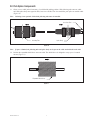
3.0 Park Splice Components
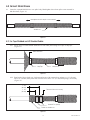
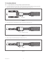
3.1 Cleanorcovercablejacketifnecessary,forcoldshrinkparkingposition.Slidejacketingtubeontoonecable
end.Slidesplicebodyontooppositecable,loosecoreendfirst.Forsizetransitions,parkspliceonsmallercable
(Figure10).
Note: Jacketingisnotoptional.Coldshrinkjacketingtubemustbeinstalled.
Loose Core End
Splice Body
Jacketing Tube
Figure10
Note: Ifspaceislimited,thejacketingtubeandsplicebodycanbeputonthecablestackedinsideeachother.
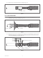
3.2 Positiontheexpandedshieldsleeveontoonecable.Theshieldsleeveisdesignedtocarryupto1/3neutral
current(Figure11).
Expanded Shield Sleeve
Figure11

8 78-8125-9898-1-C
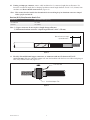
4.0 Install Connector
Note: Ifusingacrimp-typeconnector,gotostep4.3.
4.1 If using a 3M
™
Shearbolt Connector QCI 350-750, refertotheinstructionsincludedwiththeconnectorfor
insulationcut-backdimension.Insulationremovallengthshallnotexceed33/4"(95mm)fromconductorend
(Figure12).
Refer to connector instructions for dimensions
Figure12
4.2 Install3M
™
ShearboltConnectorQCI350-750accordingtotheinstructionsincludedwiththeconnector
(Figure13).
Connector
Shearbolt
Figure13
Gotosection5.0“InstallSplice.”

78-8125-9898-1-C 9
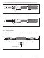
4.3 If using a crimp type connector, removecableinsulationfor1/2connectorlengthplusanallowance*for
increasesinconnectorlengthduetocrimping.Insulationremovallengthshallnotexceed33/8"(86mm)from
conductorend.Do not install connector now (Figure14).
*Note: Thisassumesthattheinstallerhasdeterminedtheincreasedlengthofanaluminumconnectorcrimped
withaspecifictoolanddie.
Aluminum (Al/Cu) Crimp Connector Growth Chart
Conductor Size Typical growth allowance (per end)
250–500 kcmil 1/4" (6 mm)
750 kcmil 3/8" (10 mm)
Note: 1)Copperconnectorsdonotrequirealengthchangeallowance.
2)Maximumaluminumconnectorcrimpedlengthallowedis6.69"(170mm).
One-half connector length
+ growth allowance*
Figure14
4.4 For 250, 350 and 500 kcmil copper connectors, or connectors with an O.D. between 0.75–1.07"
(19,1–27,2 mm): Slidethecoldshrinkadaptertubeontotheinsulationwiththeloosecoreribbonendgoingon
first,awayfromthecableend(Figure15).
Cold Shrink Adapter Tube
Loose Core End
Figure15

10 78-8125-9898-1-C
4.5 Installconnector.Seetable(oncover)forproperconnectordimensions.(Forstandard3M
™
Connectors,refer
totableattheendofthisinstructionforcrimpinginformation).Removeanyexcessoxidationinhibitorfrom
connectorendsifaluminumconnectorisused.Filesharpconnectorflashingifnecessary,takingcaretoremove
allmetalfilingsfromsplicearea(Figure16).
Connector
Figure16
5.0 Install Splice
5.1 Applyatapemarkertosemi-coninsulationshieldoncablewhichdoesnotcontainsplice.Measure101/2"
(267mm)fromcenterofconnector(Figure17).
Tape Marker
Semi-con
10 1/2"
(267 mm)
Figure17
5.2 If using cold shrink adapter tube:Positionadaptertubeovertheconnector.Shrinkadapternearcenterof
connectorbypullingandunwindingtheloosecoreendinacounter-clockwisedirection(Figure18).
Cold shrink adapter tube
Figure18

78-8125-9898-1-C 11
5.3 Cleancablesusingstandardpractice:
a.Donotallowsolventorabrasivetocontactthecablesemi-conductiveinsulationshield.
b.Donotreducecableinsulationdiameterbelow1.07"(27,2mm)specifiedforthesplice.
c.Theinsulationsurfacemustberound,smoothandfreeofcuts/voids.Sandingmaybenecessary,finish
sandingshouldbedonewitha300gritorhigherelectricalgradeabrasive.
d.Makecertainthatthecableinsulationissmooth,cleananddrybeforecontinuing.
5.4 Applyredcompoundoncableinsulations,makingcertaintofillinedgeofcablesemi-con.Do not use
silicone grease(Figure19).
Apply Red
Compound
Apply Red
Compound
Fill semi-con step Fill semi-con step
Figure19
5.5 Positionthesplicebodyoverconnectorarea,aligningendofthesplicebody(notthecore)atthecenter
ofthetapemarker.Slowlystarttoremovethesplicecorebypullingandunwindingtheloosecoreend
counterclockwise,allowingonly¼"(6mm)ofthesplicetoshrinkontothetapemarker.Carefullyslidethe
splicebodyoffthetapemarkerbypullingandtwistinguntiltheentiretapemarkerisexposed.Continue
removingthecoretocompletethesplicebodyinstallation(Figure20).
Note: Thesplicebodyendsmustoverlapontothesemi-conofeachcablebyatleast1/2"(13mm).
Note: Donotpushthesplicebodytowardthetapemarkerasthismaycausetheendtorollunder.Iftheend
doesrollunder,DONOTusesharp-edgedtoolstopullitoutasthiscouldcutanddamagethesplice.
Unwind Counter-clockwise
Align splice body with tape marker
Figure20

12 78-8125-9898-1-C
6.0 Connect Shield Sleeve
6.1 Centertheexpandedshieldsleeveoversplicebody.Hand-tightensleevefromsplicecenteroutwardin
bothdirections(Figure21).
Shield Sleeve
Hand-tighten sleeve from splice center outward
Figure21
6.2 For Tape Shielded and LC Shielded Cables:
6.2.1 Securesleevetocablemetallicshieldnexttoeachcablejacketusingtwowrapsofvinyltape
(Figure22).
Cable Jacket End
Vinyl Tape Shield Sleeve
Figure22
6.2.2 Bendendsofsleevebackovervinyltapeandsecurewithconstantforcespringsat11/2"(38mm)
and21/2"(64mm)fromjacketend.Trimoffexcesssleeve1/2"(13mm)fromsprings,ifnecessary
(Figure23).
Constant Force Springs
Folded over shield sleeve
Trim end of sleeve if necessary
1 1/2"
(38 mm)
2 1/2"
(64 mm)
Figure23

78-8125-9898-1-C 13
6.2.3 Wraptwolayersofstretchedvinyltapeoversprings(Figure24).
Vinyl Tape
Figure24
6.3 For Wire Shielded Cable:
6.3.1 Carefullyremovevinyltapefromdrainwires.Securesleevetocablesemi-conductinglayernexttoeach
cablejacketusingtwowrapsofvinyltape(Figure25).
Vinyl Tape
Drain Wires
Figure25
6.3.2 Bendendsofsleevebackovervinyltape.Positiondrainwiresovertheshieldsleeveandsecurewith
constantforcespringsat11/2"(38mm)and21/2"(64mm)fromjacketend.Trimoffexcesssleeve
1/2"(13mm)fromsprings,ifnecessary(Figure26).
Constant Force Springs
Drain wires over shield sleeve
Trim end of sleeve if necessary
1 1/2"
(38 mm)
2 1/2"
(64 mm)
Figure26

14 78-8125-9898-1-C
6.3.3 Wraptwolayersofstretchedvinyltapeoversprings(Figure27).
Vinyl Tape
Figure27
6.4 For UniShield
®
Cable:
6.4.1 Carefullyremovevinyltapefromdrainwires.Securesleevetocablesemi-conjacketnexttobent-back
shielddrainwiresusingtwowrapsofvinyltape(Figure28).
Vinyl Tape
Drain Wires
Figure28
6.4.2 Bendendsofsleevebackovervinyltape.Carefullypositiondrainwiresovertheshieldsleeve.Secure
withconstantforcesprings11/2"(38mm)and21/2"(64mm)ontodrainwires.Trimoffexcesssleeve
1/2"(13mm)fromsprings,ifnecessary(Figure29).
Constant Force Springs
Drain wires over shield sleeve
Trim end of sleeve if necessary
1 1/2"
(38 mm)
2 1/2"
(64 mm)
Figure29

78-8125-9898-1-C 15
6.4.3 Wraptwolayersofstretchedvinyltapeoversprings(Figure30).
Vinyl Tape
Figure30
6.5 For CN and JCN Cable:
6.5.1 Connectshieldsleevetometallic(LC,etc.)shieldfirst.Removevinyltapefromneutralwiresandroute
neutralwiresupwardnexttoendofcablejacket(orCNbinder)(Figure31).
Neutral Wires
Figure31
6.5.2 Securesleevetocablesemi-connexttoneutralwiresusingtwowrapsofvinyltape.Covertheendofthe
splicebody(asshownbelow)withtwohalf-lappedlayersofrubberorvinyltape(Figure32).
Neutral Wires Shield Sleeve (twisted)
Vinyl Tape
Rubber or Vinyl Tape
Figure32

16 78-8125-9898-1-C
6.5.3 Placea3-4"pieceofcablejacketovertherubberorvinyltapeandcablesemi-conasshownbelow.
Securewithvinyltape(Figure33).
Cable Jacket Piece
Figure33
6.5.4 Keepingtheconnectorascloseaspossibletothecable,connectshieldsleeveandneutralstogether,
usingasuitablecompressionconnector.(“INLINE,”“C,”or“H”type).Crimpconnectorfollowingthe
connectormanufacturer’srecommendation.Trimexcessneutralwiresandsleeveextendingbeyondthe
connector(Figure34).
Compression connector
Figure34
6.5.5 Foldconnectorovershieldsleeve,ensuringthattheconnectorisoverthecablejacketpiece,andsecure
withvinyltape(Figure35).
Vinyl Tape
Figure35

78-8125-9898-1-C 17
7.0 Grounding (Optional)
Note: Usetheseinstructionsifcircuitgroundingisrequiredatthislocation.
7.1 Onmetallicshielded(non-neutral)cable,wrapthegroundstraparoundtheshieldsleeve(betweenthecable
jacketandconstantforcespring)withthetailstowardsthecablejacket(Figure36).
Ground Strap
Figure36
7.2 Securegroundstraptotheshieldsleeveusingaconstantforcespring(Figure37).
Constant Force Spring
Figure37
7.3 Wraptwolayersofstretchedvinyltapeoverspring(Figure38).
Vinyl Tape
Figure38

18 78-8125-9898-1-C
7.4 Placeonemasticsealingstriponthecablejacketunderthesolderblocksofthegroundstrap(Figure39).
Solder Block
Mastic Strip
Figure39
7.5 Placeotherstripoverthesolderblocks.Pressthemasticstripsaroundthesolderblockandtothecablejacket.
Iftailsoverlapatthesolderblocks,placeapieceofmasticbetweenthem(Figure40).
Second Mastic Strip
Figure40
8.0 Install Jacket
Note: Jacketingisnotoptional.
8.1 Applyonerollofslightlystretchedrubbermastictapearoundeachjacketend(tackysidetowardcable).Stretch
andtearofftheendoftherubbermasticasshownbelow.Ifgroundstrapwasapplied,tapeovermasticsealing
strips.ForCNcable,covermasticsealnexttobinder(Figure41).
Stretch and tear off last 1–2"
(25–50 mm) of rubber mastic
Rubber Mastic Rubber Mastic
Figure41

78-8125-9898-1-C 19
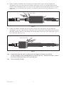
8.2 Begintoinstallthecoldshrinktubebycompletelycoveringtherubbermastic,andslowlypullingand
unwindingtheinnercorecounterclockwisetowardthesplicebody.Theoutercoreshouldremainrelatively
stationarywhileunwindingtheinnercore.Iftheoutercorebeginstomovetowardsthefirstmasticseal,gently
pulltheoutercoreandjacketingtubetowardsthesecondmasticsealandcontinueunwindingtheinnercore
(Figure42).
Unwind Counter-clockwise
Figure42
8.3 Continuetoinstallthecoldshrinktubeovertherubbermasticontheothercablebyslowlypullingand
unwindingtheoutercorecounterclockwise.Thisportionofthecoldshrinktubeinstallsdifferentlythantypical
coldshrinkproductsinthatasthetubeshrinks,theendrollsunder.Thetubemayneedaslightpushtogetover
thesecondmasticseal(Figure43).
Unwind Counter-clockwise
Figure43
Note: Inapplicationswherethespliceisregularlyexposedtohighlevelsofultra-violetradiation
(i.e.directsunlight),wraptwohalf-lappedlayersofScotch
®
Super33+
™
VinylElectricalTapeorScotch
®
VinylElectricalTapeSuper88overthere-jacketingtubes.
Note: Connectoptionalgrounding.

20 78-8125-9898-1-C
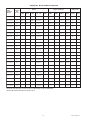
Crimping Tool - Die Sets (number of crimps/end)
*Y45 and Y46 accept all Y35 dies (“U Series”). For Y45, use PT6515 adapter. For Y46, use PUADP adapter.
**Anderson VC6-3, VC6-FT and Burndy Y1000 require no die set.
™M3
rotcennoC
rebmuN
rotcudnoC
eziS
)limck(
ydnruB . proCstteB&samohT
.oCDerauqS
.viDnosrednA
6DM 92YM A43Y
93Y,53Y
*64Y,*54Y
001Y **0 5MBT 8MBT 21MBT 51MBT
**3-6CV
F-6CV **T
8CV **C
)uC(90001 052 )3(661W )1(052 )2(R92A )2(TR92U — )2(wolleY )2(wolleY — )2(26 )2( —
)uC/lA(90002 052 )3(942W — )2(RA92A )2(TRA92U )1( — — )2(H17 )2(H17 )3( —
)uC(90011 052 )4(661W )2(052 )3(R92A )3(TR92U — )3(wolleY )3(wolleY — )3(26 )3( —
)uC/lA(052-IC 052 — — — )2(TRA13U — — — )2(H78 )2(H78 )2( —
)uC(01001 003 — — )3(R03A )2(TR03U — — )2(etihW — )2(66 )2( —
)uC/lA
(01002 003 — — )2(RA03A )2(TRA03U )1( — — )3(H67 )1(67 )2( —
)uC(01011 003 — — )3(R03A )3(TR03U — — )3(etihW — )3(66 )3( —
)uC/lA(003-IC 003 — — — )2(TRA13U — — — )2(H78 )2(H78 )2( —
)uC(11001 053 — — )2(R13A )2(TR13U — — )3(deR — )3(H17 )2( —
)uC/lA(11002 053 — — — )2(TRA13U )1( — — )3(H78 )3(H78 )2( —
)uC(11011 053 — — )3(R13A )3(TR13U — — )4(deR — )4(H17 )3( —
)uC/lA(053-IC 053 — — — )2(TRA13U — — — )2(H78 )2(H78 )3( —
)uC/lA(21002 004 — — — )4(TRA23U )1( — — )4(H49 )4(H49 )2( )2(
)uC(41001 005 — — )2(R43A )2(TR43U — — )3(nworB — )3(H78 )2( —
)uC/lA(41002 005 — — — )4(TRA43U )1( — — )3(H601 )4(H601 )2( )2(
)u
C(41011 005 — — )4(R43A )3(TR43U — — )4(nworB — )4(H78 )3( —
)uC/lA(005-IC 005 — — — )3(TRA43U — — — — )3(H601 )3( —
)uC/lA(61002 006 — — — )4(TRA63U )1( — — — )3(H511 )3( )3(
)uC(91001 057 — — — )3(TR93U — — — — )3(H601 — —
)uC/lA(91002 057 — — — )4(TRA93U — — — — )5(H521 )3( )3(
)uC(91011 057 — — — )5(TR93U — — — — )4(H601 — —
)uC/lA(057-IC 057 — — — )3(TRA93S — — — — )3(H041 )3( —
Page is loading ...
Page is loading ...
-
 1
1
-
 2
2
-
 3
3
-
 4
4
-
 5
5
-
 6
6
-
 7
7
-
 8
8
-
 9
9
-
 10
10
-
 11
11
-
 12
12
-
 13
13
-
 14
14
-
 15
15
-
 16
16
-
 17
17
-
 18
18
-
 19
19
-
 20
20
-
 21
21
-
 22
22


3M Cold Shrink QS-III Splice Kit 5525A-750-CU, 25/28 kV, 750 kcmil, 1/case Operating instructions
- Category
- Signal cables
- Type
- Operating instructions
- This manual is also suitable for
-
- Cold Shrink QS-III Splice Kit 5525A, 25/28 kV, 250-750 kcmil (120-325 mm2), 1/case
- Cold Shrink QS-III Splice Kit 5525A-250-AL, 250 kcmil, 1 per case
- Cold Shrink QS-III Splice Kit 5525A-250-CU, 25/28 kV, Standard, 1/case
- Cold Shrink QS-III Splice Kit 5525A-350-AL, 350 kcmil, 1 per case
- Cold Shrink QS-III Splice Kit 5525A-350-CU, 25/28 kV, 350 kcmil, 1/case
- Cold Shrink QS-III Splice Kit 5525A-500-AL, 25/28 kV, 500 kcmil, 1/case
- Cold Shrink QS-III Splice Kit 5525A-500-CU, Tape, Wire, Unishield, 25/28 kV, Standard, 1 per case
- Cold Shrink QS-III Splice Kit 5525A-750-AL, 25/28 kV, Standard, 1/case
Ask a question and I''ll find the answer in the document
Finding information in a document is now easier with AI
Related papers
-
3M QS Molded Rubber Splice Kit 5404, CN and JCN Cable, 15 kV, 2/0-4/0 AWG, Cable Insulation O.D. 0.920-1.080 in, 1 per case Operating instructions
-
-
-
-
-
-
-
-
-
Other documents
-
PROFESSIONAL WIRELESS SYSTEMS S4448 User manual
-
Eaton EZ II Series Installation Instructions Manual
-
Ideal 46-411 Installation guide
-
 Off Road Only LiteSPOTZ 6 Light Under Chassis Kit Installation guide
-
WarmlyYours Snow Melt and Slab Heat Repair Kit Operating instructions
-
Savant AMP-8125-00 Deployment Guide
-
-
-
Ashley H275-34R Home Office Desk User manual
-
Eureka 421A Owner's manual
