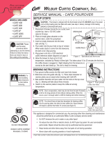
ILLUSTRATED PARTS LIST IP65
CAFE GLASS DECANTER BREWER, ILLUSTRATED PARTS/RECOMMENDED PARTS 052219A
ITEM # PART # DESCRIPTION
1 WC-54121 PAN, POUR CAFÉ
2A WC-207
1,3
LIGHT, BREW 115V GREEN
2B WC-208
2,4
LIGHT, BREW 250V GREEN
3 WC-3502 LEG, 8-32 STUD SCREW BUMPER
4 WC-3645
SPRING, DELIMING .041 X 20”
GALVANIZED WIRE HARD DRAWN
5 WC-54118 TRAY, ASSY CAFE POUR OVER
6 WC-4213-P NUT, 5/8 LOCK PLATED
7A WC-735-101K
1,3*
KIT, CONTROL MODULE RETROFIT
7B WC-735-101
1,3*
THERMOSTAT, TEMPERATURE
CONTROL 120VAC POUROVER CAFE
7C WC-504
2,4
THERMOSTAT, CAPILLARY SPST 250V
25A GEM
8 WC-39371 LABEL, SW PANEL CAFÉ AP CURTIS
9 WC-29025 SPRAYHEAD, PURPLE ADVANCE FLOW
10 WC-29054 TUBE, W/A CAFE POUR OVERS
ITEM # PART # DESCRIPTION
11 WC-3621-101
BREW CONE, NON-METAL UNIVERSAL
(WITH SPLASH POCKET)
12A WC-13301-101
1,3
HARNESS ASSY, CAFE AP 120V FOR
ELECTRONIC THERMOSTAT
12B WC-13301
2,4
HARNESS ASSY, CAFÉ AP 220V
13 WC-5310 TUBE, 5/16 ID x 1/8W SILICONE GEN USE
14 WC-1408 CORD GRIP, 7/8” O.D.
15A WC-1200
1,3
CORD, 14/3 SJTO 6’ BLK W/PLUG
15B WC-1231-103
2,4
CORD, 2.5 mm² PRE-CUT W/
CONNECTORS
16 WC-103
2,4
SWITCH, TOGGLE NON-LIT DPST 25A
125/250VAC RESISTIVE
17 WC-5231 COMPOUND, HEAT SINK 5OZ
18 WC-4426 SCREW, 8-32x3/8 PH HEAD TRUSS
19 WC-4442 SCREW, 8-32x3/8 PH HD TRUSS BLACK
20 WC-4514 SCREW, 8-32x3/8 PAN HEAD PH SS
CAFE0AP, CAFE0PP - Main Chassis - Parts List
1
CAFE0AP10A000,
2
CAFE0AP30A000,
3
CAFE0PP10A000,
4
CAFE0PP30A000
* IMPORTANT: The mounting location of the temperature control module was changed on newer units to increase reliability. If replacing a control module that is mounted near the top
of the water tank, order item 7A (includes parts and instructions for installing the replacement module in the new location). If the module is mounted just above the base of the chassis,
order item 7B.
ITEM # PART # DESCRIPTION
9 WC-29025 SPRAYHEAD, PURPLE ADVANCE FLOW
13 WC-5310 TUBE, 5/16 ID x 1/8W SILICONE GEN USE
16 WC-103
SWITCH, TOGGLE NON-LIT DPST 25A
125/250VAC RESISTIVE
ITEM # PART # DESCRIPTION
17 WC-5231 COMPOUND, HEAT SINK 5OZ
CAFE0AP, CAFE0PP - Main Chassis - Recommended Parts to Stock