Hanna Instruments BL122,BL123 Owner's manual
- Category
- Measuring, testing & control
- Type
- Owner's manual

INSTRUCTION MANUAL
BL122 · BL123
SWIMMING POOL CONTROLLERS
WITH CLOUD CONNECTIVITY

All rights are reserved. Reproduction in whole or in part is prohibited without the written consent of the copyright owner, Hanna Instruments Inc.,
Woonsocket, Rhode Island, 02895, USA.
Thank you for choosing a Hanna Instruments product.
Please read this instruction manual carefully before using this instrument.
This manual will provide you with the necessary information for correct use of this instrument, as well as a
precise idea of its versatility.
If you need additional technical information, do not hesitate to e‑mail us at [email protected] or view our
worldwide contact list at www.hannainst.com.
Dear
Customer,

3
TABLE OF CONTENTS
TABLE OF CONTENTS
POOL CONTROLLERS CONTENTS .................................................................................................................................. 4
DESCRIPTION ............................................................................................................................................................ 5
CONTROLLER OVERVIEW ............................................................................................................................................ 6
Product Diagram ................................................................................................................................................. 6
Connections, Alarm, Output and Power.................................................................................................................. 7
Ethernet Cable and Analog Output Wiring ............................................................................................................. 8
Keypad Function ................................................................................................................................................. 8
SETUP/INSTALLATION ................................................................................................................................................ 9
General Installation Guidelines ............................................................................................................................. 9
Cloud Connectivity ............................................................................................................................................... 9
Pool Controller Installation ................................................................................................................................. 10
Saddle Installation ............................................................................................................................................ 14
Probe Installation ............................................................................................................................................. 15
Installing Aspiration Filters ................................................................................................................................ 16
Installing Injectors ............................................................................................................................................ 16
Flow-Cell Installation ........................................................................................................................................ 17
Controller Menu ................................................................................................................................................ 19
User Interface Map............................................................................................................................................ 23
Hanna Cloud Setup ........................................................................................................................................... 24
User Interface in Parameter Setup ...................................................................................................................... 25
User Interface in General Setup .......................................................................................................................... 26
OPERATIONAL GUIDE ............................................................................................................................................... 27
Measurement ................................................................................................................................................... 27
pH Calibration .................................................................................................................................................. 29
ORP Calibration ................................................................................................................................................ 32
GLP Information ................................................................................................................................................ 32
Controller Modes ............................................................................................................................................... 33
Control Mode .................................................................................................................................................... 34
Security Feature ................................................................................................................................................ 36
Logging ........................................................................................................................................................... 37
Log Recall ........................................................................................................................................................ 37
Analog Outputs (BL123 only)............................................................................................................................. 39
Events Management .......................................................................................................................................... 40
SPECIFICATIONS ...................................................................................................................................................... 43
MAINTENANCE ........................................................................................................................................................ 45
Electrode Conditioning and Maintenance ............................................................................................................. 45
Pump Tube Replacement ................................................................................................................................... 45
ACCESSORIES .......................................................................................................................................................... 46
4
6
7
8
9
10
15
16
19
24
26
27
32
33
36
37
40
45
45
5
6
8
9
9
14
16
17
23
25
27
29
32
34
37
39
43
45
46

4
POOL CONTROLLERS CONTENTS
POOL CONTROLLERS CONTENTS
BL122 and BL123 are designed to maintain constant pH and disinfectant levels in swimming pools and offer the added
benefit of allowing remote connection and access to devices via cloud connectivity.
Remove the instrument and accessories from the packaging and verify that no damage has occurred during shipping. Remove
the protective film from meter. Notify your nearest Hanna Instruments Customer Service Center if damage is observed.
For each model two versions are available: Inline BL122-10, BL123-10 and flow cell BL122-20, BL123-20.
Additionally, BL123 has three analog outputs.
Each instrument is supplied with:
Inline BL122-10/BL123-10
• BL122/BL123 Swimming Pool Controller
• HI1036-1802 Combined electrode (pH/ORP/
Temperature/Matching Pin)
• Saddle for electrode 50 mm (1 pc.)
• Fittings for electrode
• Injector (2 pcs.)
• Saddle for injectors 50 mm (2 pcs.)
• Peristaltic pump tubing (2 pcs.)
• Suction and injection tubing 10 m
• Aspiration filter (2 pcs.)
• Aspiration filter weight (2 pcs.)
• pH 7.01 sachet (3 pcs.)
• pH 4.01 sachet (3 pcs.)
• 470 mV ORP test solution sachet (3 pcs.)
• Power cable
• User manual
Panel mounted flow cell BL122-20/BL123-20
• BL122/BL123 Swimming Pool Controller
• Panel mounted flow cell
• HI1036-1802 Combined electrode (pH/ ORP/
Temperature/Matching Pin)
• Two valves for flow-cell connections with fittings and
tubing 10 m
• Injector (2 pcs.)
• Saddle for injectors 50 mm (2 pcs.)
• Saddle for valves 50 mm (2 pcs.)
• Peristaltic pump tubing (2 pcs.)
• Suction and injection tubing 10 m
• Aspiration filter (2 pcs.)
• Aspiration filter weight (2 pcs.)
• pH 7.01 sachet (3 pcs.)
• pH 4.01 sachet (3 pcs.)
• 470 mV ORP test solution sachet (3 pcs.)
• Power cable
• User manual
Note: Save all packing material until you are sure that the instrument works correctly. Any defective item must be returned
in its original packing.

5
DESCRIPTION
DESCRIPTION
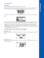
The BL122 and BL123 Swimming Pool Controller are automatic systems designed to measure and control pH and free
chlorine levels in swimming pools (or hot tubs) and remotely access and visualise measured data via cloud connectivity. All
measurements and main events are sent to Hanna Cloud through the Ethernet connection.
The chlorine level is measured based on the ORP of REDOX principle. An increase of the ORP value correlates with an increase
of the free chlorine level. pH and disinfectant testings are made together for more efficient disinfection and control. The
efficacy of sanitizers, is dependent on a controlled pH value. The ORP value is the most consistent indicator of the sanitizing
effectiveness of the pool/hot tub or water treatment. Typically 650-750 mV at 7.2 pH indicates proper water treatment
(all harmful bacteria are killed in less than 1s). pH and disinfectant testings are made using the HI1036-1802 combined
electrode installed inline or in flow cell. To prevent the ground loop effects from causing erratic readings and damage to
the system the electrode has a matching pin considered the “earth ground“ connection. The HI1036-1802 uses a Ag/AgCl
reference with 3.5 M KCl. It was specially designed to detect the broken electrode based on a shiffted ISO potential value. The
ORP values are referenced to it.
It is the responsibility of the user/installer to determine an ideal setpoint for pH (e.g. 7,4) and ORP (e.g. 760 mv). The
Swimming Pool Controller will dose acid in case the water pH is above the pH setpoint and it will dose chlorine in case the
ORP value is lower than the ORP setpoint.
Although the Swimming Pool Controller is an automatic system, the user/installer should check the Swimming Pool Controller
and verify free chlorine and pH levels (in mg/L or ppm) in the pool, using a portable meter for pH and free chlorine.
All measurements and the main events are logged in the internal memory of the Pool Controller and can be viewed using the
plot/record log recall feature or exporting the data on a USB key for advanced data processing on a PC.
The Swimming Pool Controller should only be used in combination with liquid acid (e.g. sulfuric acid) and liquid chlorine
(e.g. sodium hypochlorite).
Do not use chlorine tablets, granular chlorine or other non-liquid chlorine applications.
Do not use the Pool Controller in a pool utilizing electrolytic chlorine generation (salt electrolysis).
Do not add stabilizer (e.g. cyanuric acid) to the swimming pool while using Pool Controller. To remove stabilizer
from the pool, the pool contents must be removed and the pool cleaned.
The main operating modes of Swimming Pool Controller are measurement, dosing, setup and logging. Follow this general
outline of steps to get you started..

6
CONTROLLER OVERVIEW
CONTROLLER OVERVIEW
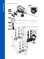
PRODUCT DIAGRAM
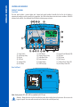
Front Panel
The front panel includes a custom display and keypad with tactile feedback. Normally the first line of the display is
measurement readings, and the second line is temperature. Two LEDs indicate alarm status and service conditions. A Red LED
indicates fault condition. Two additional blue LEDs flash, indicating pump activation.
1) Power Switch
2) Acid Dosing Pump
3) IN Acid
4) OUT Acid
5) Leakage Holes
6) IN Chlorine
7) OUT Chlorine
8) Chlorine Dosing Pump
9) Cable Gland Seals
10) Probe Connector
11) Keyboard Area
12) USB Port (host)
13) Liquid Crystal Display (LCD)
14) LED Area
15) LED Status
16) LED Service
17) Chlorine Pump Status LED
18) Acid Pump Status LED
Rear Sub Panel
Note: Analog outputs AO1, AO2, AO3 are available for BL123 only.
Warning! Always disconnect the Pool Controller from power when making electrical connections. Do not access the
larger rear panel. User-serviceable terminals can be found in the small sub panel only.

7
CONTROLLER OVERVIEW
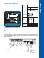
CONNECTIONS, ALARM, OUTPUT AND POWER
ANALOG
OUTPUTS
(BL123 only)
A01
+
4 - 20 mA OUT
-
A02
+
4 - 20 mA OUT
-
A03
+
4 - 20 mA OUT
-
ETHERNET RJ-45 connector
DIGITAL INPUTS
ALARM RELAY
POWER INPUT
N Neutral
Protective Earth
L Line
Note: Analog outputs AO1, AO2, AO3 are available for BL123 only.
Warning! Always disconnect the Pool Controller from power when making electrical connections.
There are 4 opening for wiring. The left rear openings are for power and digital input wiring. Note: Do not run power cabling
through the same opening with other cables. The left front opening is for alarm relay wiring. Sensor wiring is made using the
connector with threaded seal. The larger right opening is for analog output wiring and the Ethernet cable. Seal any unused
openings with conduit plugs.
Gland Seals for
Inputs Cable
Alarm Relay
Cable
Sensor
Input
Analog Outputs
Cable
(BL123 only)
Ethernet
Cable
Power Cable
Do not run other cables
with the Power Cable

8
CONTROLLER OVERVIEW
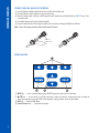
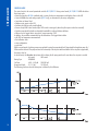
ETHERNET CABLE AND ANALOG OUTPUT WIRING
1) Insert the Ethernet cable through the knurled nut and the slotted rubber seal.
2) Insert the Ethernet cable through the casing into the housing.
3) Insert the analog output connection cable through the same knurled nut and slotted rubber seal (BL123 only). Use a
6 conductor cable.
4) Feed cables through seal to reach intended terminals.
5) Insert the rubber seal into the housing, then tighten the connection by turning the knurled nut clockwise.
Note: Connect the analog connections before connecting the Ethernet.
Nut
Housing
Rubber seal
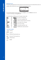
KEYPAD FUNCTION
1) MENU Key – Access to manual pump control, pH/ORP/Temperature options and General setup
2) / Keys – In menu mode, to scroll the menu items / adjust the settings In measurement mode, to change the
screen: three parameter screen (pH, ORP, and Temperature), single parameter screen and plot display
3) HELP Key – Enter/Exit Help Menu
4) Virtual Function Keys – Contextual functionality

9
SETUP/INSTALLATION
SETUP/INSTALLATION
GENERAL INSTALLATION GUIDELINES
The following tasks require mechanical, plumbing and electrical skills. These should be made by qualified personnel. Two
configurations are available:
Inline configuration: - the probe is placed in saddle, mounted on pipe after the pool filter.
Flow-cell configuration: - the probe is mounted in the flow cell, close to the controller. The water sample is directed to the Flow
cell via a small diameter sample line with appropriate connections (provided). In flow-cell configuration the water circulation
can be stopped by closing the valve on the inlet while maintenance or calibration procedures are performed.
• When selecting installation location, ensure that the controller is shielded from direct sunlight, dripping water or excess
vibrations.
• For inline installation, the probe saddle should be positioned after the pool filter (within 2 m distance).
Caution: Use gloves, protective clothing and eye protection goggles when working with Injectors and Tubing.
Determine if a flow detector, or alarm relays or analog outputs (BL123) will be used before mounting flow cell
panel or Pool Controller, as access to rear sub panel is needed.
CLOUD CONNECTIVITY
Go to www.hannacloud.com and follow the required steps to create an account.
After login, the user can access the online user guide which contains detailed information on Hanna cloud functionalities.

10
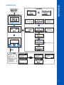
SETUP/INSTALLATION
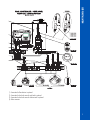
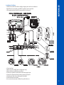
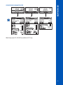
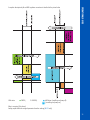
POOL CONTROLLER INSTALLATION
BL120-203

11
SETUP/INSTALLATION
1 8
HANNA CLOUD
BL123-20
1) Connection for flow detector is optional.
2) Connection for low level sensor for acid tank is optional.
3) Connection for low level sensor for chlorine tank is optional.
4) Probe connector.

12
SETUP/INSTALLATION
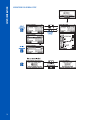
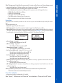
Using a Phillips head screwdriver remove the screws. After opening, lift the
back cover and remove it.
To insert in place, attach the bottom part of the cover to the controller and
push to close. Tighten the screw with the screwdriver.

13
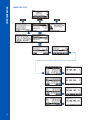
SETUP/INSTALLATION
Installation Guidelines
• Shield the controller from direct sunlight, dripping water and excess vibrations.
• Keep flow rate as constant as possible for optimum sensor operation.
• The sample analyzed should be representative of entire pool.
HANNA CLOUD
BL123
• Check tank level.
• Mount the probe saddle (inline configuration only).
• Mount the injector saddle (see procedure).
• Connect the aspiration tubes between tanks and pumps input.
• Connect the dispensing tubing between pumps and injectors.
• Check the low level sensors functionality if enabled.
• Check hold input functionality.
• For accurate measurements calibrate the probe before use.

14
SETUP/INSTALLATION
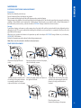
SADDLE INSTALLATION
Saddles are used for the probe installation in an inline installation, and for injector installations in both inline and flow cell
installations. Select pipe locations that are accessible with sensor cable length and tubing.
Saddle for Probe (in-line) Saddle thread size Drill size Min. - Max.
BL120-550 50 mm pipe 1 - ¼”thread 29 mm - 32 mm / 1.1417” - 1.2598”
BL120-563 63 mm pipe 1 - ¼”thread 29 mm - 32 mm / 1.1417” - 1.2598”
BL120-575 75 mm pipe 1 - ¼”thread 29 mm - 32 mm / 1.1417” - 1.2598”
Fittings for Valves for Flow-cell connections Saddle thread size Drill size Min. - Max.
BL120-450 50 mm pipe ½”thread 20 mm - 25.4 mm / 0.7874” - 1.0000”
BL120-463 63 mm pipe ½”thread 20 mm - 25.4 mm / 0.7874” - 1.0000”
BL120-475 75 mm pipe ½”thread 20 mm - 25.4 mm / 0.7874” - 1.0000”
Saddle for Injectors Saddle thread size Drill size Min. - Max.
BL120-250 50 mm pipe ½”thread 20 mm - 25.4 mm / 0.7874” - 1.0000”
BL120-263 63 mm pipe ½”thread 20 mm - 25.4 mm / 0.7874” - 1.0000”
BL120-275 75 mm pipe ½”thread 20 mm - 25.4 mm / 0.7874” - 1.0000”
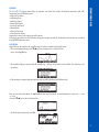
Using a 29 mm (1.14173”) drill, make a hole at the desired location on the pipe, where the saddle will be mounted
(50 mm; 63 mm; 75 mm available).
The saddle will be mounted above the hole in the following order:
• Place the upper saddle (5) part with seal (4) mounted around the
hole.
• Place the lower part (2) of the saddle, together with inserted nuts (1)
into location.
• Insert a screw (7) through the hole with washer (6) mounted and
screw into the mounted nuts.
• Mount all the screws (7) by hand, then using a wrench screw them
carefully until tightened.
• Place the o-ring (8) provided , into the upper saddle.
Set saddle aside.

15
SETUP/INSTALLATION
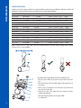
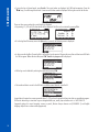
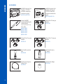
PROBE INSTALLATION
The probe should be connected to controller and calibrated before it is installed in the pipe.
1) Remove protective cap
and verify if the o-ring
is in place.
2) Insert the nut on the
probe.
3) Screw carefully the
adapter on the probe.
Do not to damage the
o-ring.
4) Insert the prepared
probe with the adapter
and screw it carefully
into the saddle. You
are now ready for
connecting the probe
to the Swimming Pool
Controller.

16
SETUP/INSTALLATION
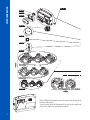
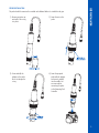
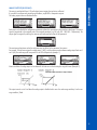
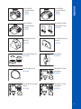
INSTALLING ASPIRATION FILTERS
Aspiration filters are used in the reagent tanks
to filter debris from entering the tubing.
1) Cut required length of suction/injection
tubing to reach between peristaltic pump
and reagent tanks.
2) Place the aspiration filter weight and the
compression fitting nut on the tubing.
3) Place the end of tubing on the filter.
4) The compression fitting has to be screwed
until secured on the filter.
5) Slide the compression fitting from the peristaltic pump inlet (up arrow) onto the tubing.
6) Place the aspiration filter weight over the filter.
7) Slide the end of tubing over the fitting of the peristaltic pump tubing.
8) Slide compression fitting up over tubing.
9) Tighten on fitting.
10) Repeat for second aspiration filter.
11) Place into appropriate reagent tank.
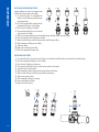
INSTALLING INJECTORS
1) Cut required length of suction/injection tubing to reach between saddle for injector and outlet of peristaltic pump.
2) Place the compression fitting nut on the tubing.
3) Place the end of tubing on the injector.
4) The compression fitting has to be screwed until secured on the injector.
5) Screw the injector in the saddle.
6) Slide compression fitting from peristaltic pump tubing onto tubing.
7) Slide the end of tubing over fitting of peristaltic pump tubing.
8) Verify correct pump is used.
9) Slide compression fitting over tubing.
10) Secure and tighten on fitting.
11) Repeat for second injector.
5.
2. 6.4.3.
4.
2. 3.

17
SETUP/INSTALLATION
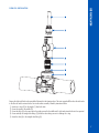
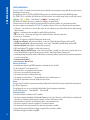
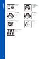
FLOW-CELL INSTALLATION
Prepare the Inlet and Outlet valve assemblies illustrated in the drawing above. The water sample will flow from the inlet valve
to the flow cell and be returned to the line via the outlet assembly. Assembly instructions follow:
1) Insert two o-rings (2) on the nipple (1) from both sides.
2) Screw the nipple in the saddle (3).
3) Screw the valve (4) in the open end on the nipple screwed in the saddle until is tight and oriented in front to be operated.
4) Screw carefully the straight tube fitting (5) inside the valve taking care not to damage the o-ring.
5) Insert the tube (6) in the straight tube fitting (5).

18
SETUP/INSTALLATION
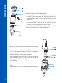
Assemble and mount the flow cell as illustrated below.
• Take one o-ring (4) and mount on the flow-cell cap (5). Insert these on flow-
cell tube (2) on the far end from lateral hole. Mount one flow-cell nut (3) by
screwing over the flow cell cap. Screw the straight tube fitting (6) in the hole
of flow cell cap.
• Take the second o-ring (4) and mount on the flow-cell adapter (1). Insert
these on flow-cell tube (2) on the near end from lateral hole. Mount the
second flow-cell nut (3) by screwing over the flow-cell adapter.
• Screw the elbow tube fitting (7) into the lateral hole of the flow-cell tube (2).
• Place the o-ring (8) provided, into the flow-cell adapter (1).
Connect probe to controller; prepare and calibrate the probe prior to installing
in the flow cell.
• Remove protective cap and verify if the o-ring (10) is in place. Insert the
nut (13) on the probe. Screw the adapter carefully (12) on the probe. Do
not damage the o-ring.
• Mount the collar (15) on the panel with the provided screw.
• Insert the assembled flow cell into the collar (15) and secure it by closing.
• Insert the prepared electrode (11) into the flow cell, carefully, not
damaging the o-ring, until the adapter (12) mounted on the electrode is
inside the flow cell.
• Screw the nut (11) until the electrode and flow-cell assembly is secured.
• Insert the tube (14a) from the aspiration valve already mounted on the
saddle.
• Insert the tube (14b) from the dispensing valve already mounted on the
saddle.

19
SETUP/INSTALLATION
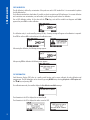
CONTROLLER MENU
The controller menu is grouped into seven categories:
• Acid (or base) Pump control
• Cl
2
Pump control
• pH Options (CAL, Setup, GLP)
• ORP Options (CAL, Setup, GLP)
• Temperature Options (Setup)
• Hanna Cloud Options
• General
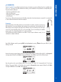
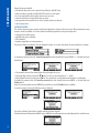
Manual/Auto Pump Control for pH or Chlorine Control
Each pump can be set to MANUAL control by selecting the On 10s/OFF options.
When On 10s is selected the pump runs continuously for 10s. To increase the time up to 90 seconds press the Add 10s button.
The remaining time is displayed next to the selected pump in the menu. Pressing the OFF button will stop the pump. To return
to the automatic mode select AUTO for each pump. In Auto mode the pumps will be activated when the measurement exceeds
the set point value.
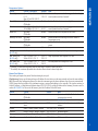
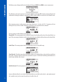
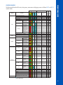
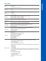
pH Options
Option Choices / Resolution Default Note
Dosing Type Acid/Base Acid Use the required option according to the tank content.
Set Point 6.00 to 8.00 pH / 0.01pH 7.2 pH Use to set the expected pH level in pool. When the pH
pump is activated, the pump LED flashes.
Proportional band 0.1 to 2.0 pH / 0.1 pH 2.0 pH pH regulated time proportional band. Proportions the
time off and time on within the band. The pump is ON
continuously at the set point value with added band.
pH Flow rate 0.5 to 3.5 l/h / 0.1 l/h 2.2 L/h pH dosing pump flow rate
Overtime 1 to 120 min / 1min 30 min Maximum allowed dosing time in automatic mode
Alarm High (pH Low+0.1) to 14.0 pH
Acid / 0.1 pH
8.0 pH Minimum pH value that triggers the alarm high event if
it persists more than 5 seconds*. Status and service LED
will activate and pH pump will be disabled.
Alarm High
Enable
Disable
Disable Enable/Disable the pH high alarms
Alarm Low 0.0 to (pH High-0.1) pH
Acid / 0.1 pH
6.0 pH Maximum pH value that triggers the alarm low event if it
persists more than 5 seconds**. Status and service LED
will activate and pH pump will be disabled.
Alarm Low
Enable
Disable
Disable Enable/Disable the pH low alarms
Warnings and Errors
Enable
Disable
Disable Enable/Disable the warnings and errors related to pH
events
Alarm Activates Relay
Enable
Disable
Disable Enable/Disable the relay control for pH events
Startup Dosing Delay 1 to 180 min / 1 min 2 min The delay to start dosing at power-on
Analog Out
(BL123 only)
Disabled, AO1, AO2, AO3 Disabled Assign an analog output to pH reading
Max. Analog Out
(BL123 only)
1 to 14 pH / 1 pH 14 pH High pH limit assigned to 20 mA

20
SETUP/INSTALLATION
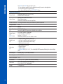
Min. Analog Out
(BL123 only)
0 to 13 pH / 1 pH 0 pH Low pH limit assigned to 4 mA
Acid Tank Input
Enable
Disable
Disable Enable/Disable the acid tank low level input
* If enabled, the minimum adjustable value of alarm high is related to alarm low value.
** If enabled, the maximum adjustable value of alarm low is related to alarm high value.
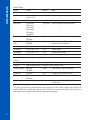
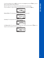
ORP Options
Option Choices / Resolution Default Note
Set Point 200 to 900 mV / 1 mV 700 mV Use to set the expected ORP level in pool.
Proportional band 10 to 200 mV / 1 mV 100 mV ORP regulated time proportional band. Proportions the
time off and time on within the band. The pump is on
continuously at the set point value with added band.
Cl
2
Flow rate 0.5 to 3.5 l/h / 0.1 L/h 2.2 L/h ORP dosing pump flow rate
Overtime 1 to 120 min / 1 min 30 min Maximum allowed dosing time in continuous mode
Alarm High (Low+1) to 1000 mV /
1 mV
900 mV Minimum ORP value that triggers the alarm high event if
it persists more than 5 seconds*. Status and Service LED’s will
activate and Cl
2
pump will be disabled.
Alarm High
Enable
Disable
Disable Enables/Disables the ORP high alarms.
Alarm Low 0 to (High-1) mV / 1 mV 200 mV Maximum ORP value that triggers the alarm low event if
it persists more than 5 seconds**. Status and Service LED’s
will activate and Cl
2
pump will be disabled.
Alarm Low
Enable
Disable
Disable Enables/Disables the ORP low alarms.
Warnings and Errors
Enable
Disable
Disable Enables/Disables the warnings and errors related to ORP
events
Alarm Activates Relay
Enable
Disable
Disable Enables/Disables the relay control for ORP events.
Startup Dosing Delay 1 to 180 min / 1 min 5 min The delay to start dosing at power-on
Analog Out
(BL123 only)
Disabled, AO1, AO2, AO3 Disabled Assigns an analog output to ORP reading.
Max. Analog Out
(BL123 only)
-1999 to 2000 mV / 1 mV 2000 mV High ORP limit assigned to 20 mA
Min. Analog Out
(BL123 only)
-2000 to 1999 mV / 1 mV -2000 mV Low ORP limit assigned to 4 mA
Cl
2
Tank Input Enable
Disable
Disable Enable/Disable the Cl
2
tank low level input
* If enabled, the minimum adjustable value of alarm high is related to alarm low value.
** If enabled, the maximum adjustable value of alarm low is related to alarm high value.
Page is loading ...
Page is loading ...
Page is loading ...
Page is loading ...
Page is loading ...
Page is loading ...
Page is loading ...
Page is loading ...
Page is loading ...
Page is loading ...
Page is loading ...
Page is loading ...
Page is loading ...
Page is loading ...
Page is loading ...
Page is loading ...
Page is loading ...
Page is loading ...
Page is loading ...
Page is loading ...
Page is loading ...
Page is loading ...
Page is loading ...
Page is loading ...
Page is loading ...
Page is loading ...
Page is loading ...
Page is loading ...
Page is loading ...
Page is loading ...
Page is loading ...
Page is loading ...
-
 1
1
-
 2
2
-
 3
3
-
 4
4
-
 5
5
-
 6
6
-
 7
7
-
 8
8
-
 9
9
-
 10
10
-
 11
11
-
 12
12
-
 13
13
-
 14
14
-
 15
15
-
 16
16
-
 17
17
-
 18
18
-
 19
19
-
 20
20
-
 21
21
-
 22
22
-
 23
23
-
 24
24
-
 25
25
-
 26
26
-
 27
27
-
 28
28
-
 29
29
-
 30
30
-
 31
31
-
 32
32
-
 33
33
-
 34
34
-
 35
35
-
 36
36
-
 37
37
-
 38
38
-
 39
39
-
 40
40
-
 41
41
-
 42
42
-
 43
43
-
 44
44
-
 45
45
-
 46
46
-
 47
47
-
 48
48
-
 49
49
-
 50
50
-
 51
51
-
 52
52


Hanna Instruments BL122,BL123 Owner's manual
- Category
- Measuring, testing & control
- Type
- Owner's manual
Ask a question and I''ll find the answer in the document
Finding information in a document is now easier with AI
Related papers
-
Hanna Instruments BL120 Owner's manual
-
-
-
Hanna HA504822-2 Owner's manual
-
-
-
-
-
-
Other documents
-
 Hach pHD Sensor User manual
-
Steinbach 018255 Operating instructions
-
Pool Technologie OPT23PER05 Operating instructions
-
CMP Del Ozone Spa Check Valve Owner's manual
-
 Hach CLT10sc User manual
-
Waterco Chemflo Plus User manual
-
 Hach CLT10sc User manual
-
ADWA AD1000 User manual
-
-
Hanna HI3512 Operating instructions


