GE RAB7120B Installation guide

Type
Installation guide

This manual is also suitable for

1
CRITICAL DIMENSIONS
NOTE:
Care should be taken in location of electrical supply
entry in relationship to wall sleeve to ensure access
to power once the unit is installed.
31-30779-1 02-16 GE
INSTALL CASE LEVEL IN ALL DIRECTIONS
NOTES:
Handle the case carefully.
The cardboard stiffener inside the case, and the rear
protective panel must remain in place until the chassis
is installed to assure case rigidity and squareness.
If a sub-base is to be used, it may be desirable to
assemble it to the case before securing the case
in the wall.
CASE LOCATION
Case must be located on an outside wall for proper
operation. As a general rule the air conditioner
should be centrally located in an outside wall to
ensure proper distribution of conditioned air. It should
be located in a portion of the wall where there is no
electrical wiring or plumbing, and where there are no
obstructions immediately inside or outside.
For further details, refer to the GE Architects & Engineers Design Data Manual for Zonelines. To obtain a copy of that
manual, call the GE Answer Center
®
at 800.626.2000 or visit us at www.Zoneline.com.
Ceiling
“A”
“B”
“C”
Roomside
Outside wall
“D”
Finished floor or top of carpet
Outside wall
“E”
“E”
Top of case
Printed in the United States
RECOMMENDED
DIMENSIONS INSTALLATION CLEARANCE
A 7RSRIFDVHWRILQLVKHGFHLOLQJ³s min.
B Projection of case into room from finished
wall - 1/4s min. (no sub-base)
2
ø8s min. when sub-base is used.
If more than 6s of the case projects
into the room, a sub-base or other
support is recommended.
C 3URMHFWLRQRIFDVHWRRXWVLGH³s min.
D Height above finished floor or
WRSRIFDUSHW³
0s min. without sub-base
 s min./5” max. with sub-base
E Left/Right side of case to adjacent
ZDOO³s min.
Installation Instructions
for your new
Before you begin - Read these instructions completely and carefully.
IMPORTANT – OBSERVE ALL GOVERNING CODES AND ORDINANCES.
Note to Installer – Be sure to leave these instructions with the Consumer.
Note to Consumer – Keep these instructions with your Owner’s Manual for future reference.
RAB71B Standard
or RAB7116B &
RAB7124B
Extended Room Air Conditioner Case
for AZ Series Zoneline Models Only
STEP 1
Preparation of the wall
The wall case should be installed during construction
and lintels should be used to support the block above
the wall case. The case will not support the concrete
block or brick. The case is modular in height and
width:
+HLJKW ³)LWVFRXUVHVFRQFUHWHEORFN
³)LWVFRXUVHVVWDQGDUGEULFN
³)LWVFRXUVHVMXPEREULFN
:LGWK ³)LWVDSSUR[LPDWHO\VWXGVSDFHV
For existing construction, wall openings must be
made. Wall openings of the proper dimensions are
essential to avoid the necessity of fillers or additional
framing.
NOTE:
Use lintel to support brick, block, etc., above the air
conditioner case. (If directly under a window sill,
the use of a lintel may not be necessary.)
STEP 2
Preparation of the case
Do not remove the cardboard stiffener inside the case
until the chassis is installed.
If field-supplied case angles are to be used and must
be installed, proceed as follows:
1. Position the case angles around top and sides
of the case at the desired location (front to rear)
with angles facing toward rear (outside). Position
the case angles vertically on each side of the case
to provide a level installation.
2. Mark the case through the holes in the case angles.
3. 'ULOOs diameter holes at marked locations
on the case and assemble the angles using only
#10u1/2s screws. Install the screws from the
outside of the case.
NOTE:
Do not drill any holes in bottom of the case.
2
Roomside
Case
Case angle
(field-supplied)
Block
Brick
42
1
/
2
16
1
/4
Main stud
Jack studs
+HDGHU³s× 4s or
two 2s× 4s on edge
16
1
ø4s Min.
42
1
ø4s Min.
“D”*
Jack studs
Cripple
Adjust
framing to
secure these
dimension
( *See chart
on page 1)
* Dimensions may need to be increased to fit unique situations in the field if using
case angles.
MINIMUM
FINISHED OPENING
DIMENSIONS*
CASE DIMENSIONS
Height Width Height Width Depth
16
1
/4 42
1
/4 16” 42”
RAB71B RAB7116B RAB7124B

/4 16” 24”
STEP 3
Installation of the case in the wall opening
1. Position the case into the wall. Refer to chart on
page 1 for roomside projection. The rear (outside)
edge of the case should extend at least 1/4s beyond
the outside wall to be able to caulk properly and
prevent sealing the drain holes in the rear flange
of the case, and to facilitate easy installation of
an accessory drain, if desired. (If it is desired to have
the rear grille flush on the outside, a drip rail must
be installed under the case and caulking applied
between the drip rail and case.) See instructions in
Step 4.
IMPORTANT:
Install case level from side to side and from front to
rear. Using a level, allowable tilt to the outside is
maximum of 1/4” bubble. Never allow case to tilt to
the inside.
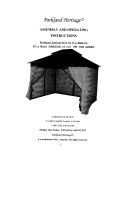
2. Firmly secure the case to the wall structure.
Do not drill any holes in the bottom of the case.
3. Caulk the entire opening on the outside between
the case and the building exterior.
4. Caulk the entire opening on the inside between
the case and the building interior.
Use lintel, when required, to support brick and block
above the case.
NOTE:
Do not drill any holes in the case for electrical
connections. See the Zoneline Air Conditioner Owner’s
Manual for instructions on how to connect the
electrical supply.
STEP 4
Weatherproofing
Weatherproof gaps between the exterior and interior
walls and the case with caulking or equivalent
weatherproofing material.
NOTE:
* It is critical to caulk around perimeter of wall case
on all four sides on the outside and the roomside
where it joins the building to prevent air and water
infiltration.
For installation in extra thick walls
1. If the case is being installed in a thick wall where
WKHFDVHLVUHFHVVHGPRUHWKDQ,s an extended
wall case will be required with depths as called
out in the table in Step 1.
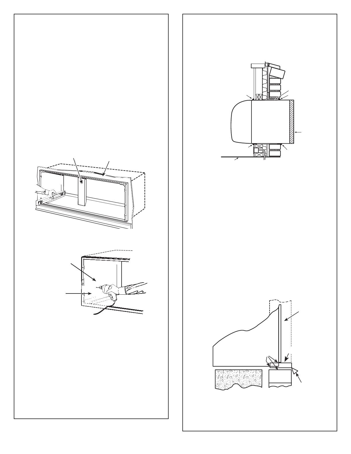
2. If the case is being installed in a wall where the
UHFHVVLVs or less, and an extended wall case is
not used, flashing must be installed under the case
and extend up 2s on each side. The flashing must
include a drip rail as illustrated in the figure below.
NOTE:
** It is critical to caulk around perimeter of
flashing and drip rail where it joins the building
and case to prevent air and water infiltration.
3
Inside wall
Stiffener
Caulk*
Steel lintel
Caulk*
Outdoor
grille
Room
cabinet
Caulk*
Case
Caulk*
Finished floor or top of carpet
Outdoor
grille
Drip rail
Case
Caulk**
Flashing
Secure case through
side and/or top only
2” min. from
case bottom
DRAIN KIT
If it is necessary to install a drain kit on this wall case,
the following kit is available:
RAD10 Internal/External Drain
1. With an “Internal Drain,” the condensate drain tube
must be connected to an internal drain system
in the building.
2. With an “External Drain” (which may be connected
to a field-supplied drain line), condensate water
can be drained away from the unit and building.
NOTE:
It may be desirable or necessary to install the drain kit
on the case prior to installing the case into
the wall.
Specifications subject to change without notice
A Quality Product of GE Appliances
ELECTRICAL REQUIREMENTS (265V)
WARNING:
Connection of a 265V product to a branch
circuit MUST be done by direct connection to be in
compliance with the National Electric Code. Plugging
a 265V unit directly into a building-mounted exposed
receptacle is not permitted by code.
See the Owner’s Manual for how to connect
the electrical supply.
4
ELECTRICAL REQUIREMENTS (230V/208V)
Provisions should be made to have the proper
electrical outlet near the case. All wiring should be
made in accordance with local codes and regulations.
The line cord included with the chassis (if used) will
extend to a wall receptacle located within the area
shown in tabulation below.
Wall Receptacles
All wiring should be made in accordance with local
electrical codes and regulations.
See the Owner’s Manual for how to connect electrical
supply.
NOTE:
Aluminum wiring in structure may pose special
SUREOHPV³FRQVXOWDTXDOLILHGHOHFWULFLDQ
99DPS 99DPS 99DPS
“tandem” type “perpendicular” type large “tandem” type
SCREW
Type “A”
METAL
See detail
below
Overflow relief drain
Square drain holes
Neoprene sponge gasket
Steel mounting plate
Type “A” screws
Ga ske t
Speed nuts
Cabinet bottom
Tub e
Cover plate
Type “A” screws
1/2 O.D.
Note: Shaded parts
included with
RAD10 drain kit
WALL CASE WITH RAD10 DRAIN UNIT
INTERNAL DRAIN
Overow relief drains
Square drain holes
Neoprene sponge gasket
Steel mounting plate
Type “A” screw s
1/2 O.D. drain tube
Note: Shaded parts
included with
RAD10 drain kit
WALL CASE WITH RAD10 DRAIN UNIT
EXTERNAL DRAIN
Inside
“F ”
“G
Model “F” “G”
AZ Series 21” max. 58” max.
  • Page 1 1
  • Page 2 2
  • Page 3 3
  • Page 4 4
  • Page 5 5
  • Page 6 6
  • Page 7 7
  • Page 8 8
  • Page 9 9
  • Page 10 10
  • Page 11 11
  • Page 12 12

GE RAB7120B Installation guide

Type
Installation guide
This manual is also suitable for

Ask a question and I''ll find the answer in the document

Finding information in a document is now easier with AI