Page is loading ...

1GPSMAP 4000/5000 Series Installation Instructions
GPSMAP
®
4000/5000 SerieS inStAllAtion inStructionS
The GPSMAP 4000/5000 series chartplotter and GPS 17 antenna must be properly installed according to the following instructions. You
need the appropriate fasteners, tools, and mounts listed in each section. These items are available at most marine dealers. Always wear safety
goggles, ear protection, and a dust mask when drilling, cutting, or sanding. When drilling or cutting, always check what is on the opposite side
of the surface. Mount the GPSMAP 4000/5000 series unit in a location that provides a clear, glare-free view of the display and easy operation
of the controls or touch screen.
To install the GPSMAP 4000/5000 series unit:
1. Mount the unit.
2. Mount the antenna.
3. Connect the unit to power and to the antenna.
4. Ensure the unit software is up-to-date.
Though they are not necessary to use the GPSMAP 4000/5000 unit, this manual covers other installation options:
• Connect the unit to other network compatible Garmin devices, such as a sounder or radar.
• Connect the unit to other NMEA 0183 compatible devices such as a VHF radio with DSC.
• Connect the unit to an external alarm.
• Connect the unit to a NMEA 2000 source (available on some boats) for various mechanical and navigation information.
• Connect the unit to a video input source.
• Connect the unit to an external video monitor.
Surface Mounting the GPSMAP 4000/5000 Series Unit
Tools required (not included):
• Drill and drill bit
• Screwdriver
• Pencil
• Mounting hardware (screws or nuts, washers, and bolts)
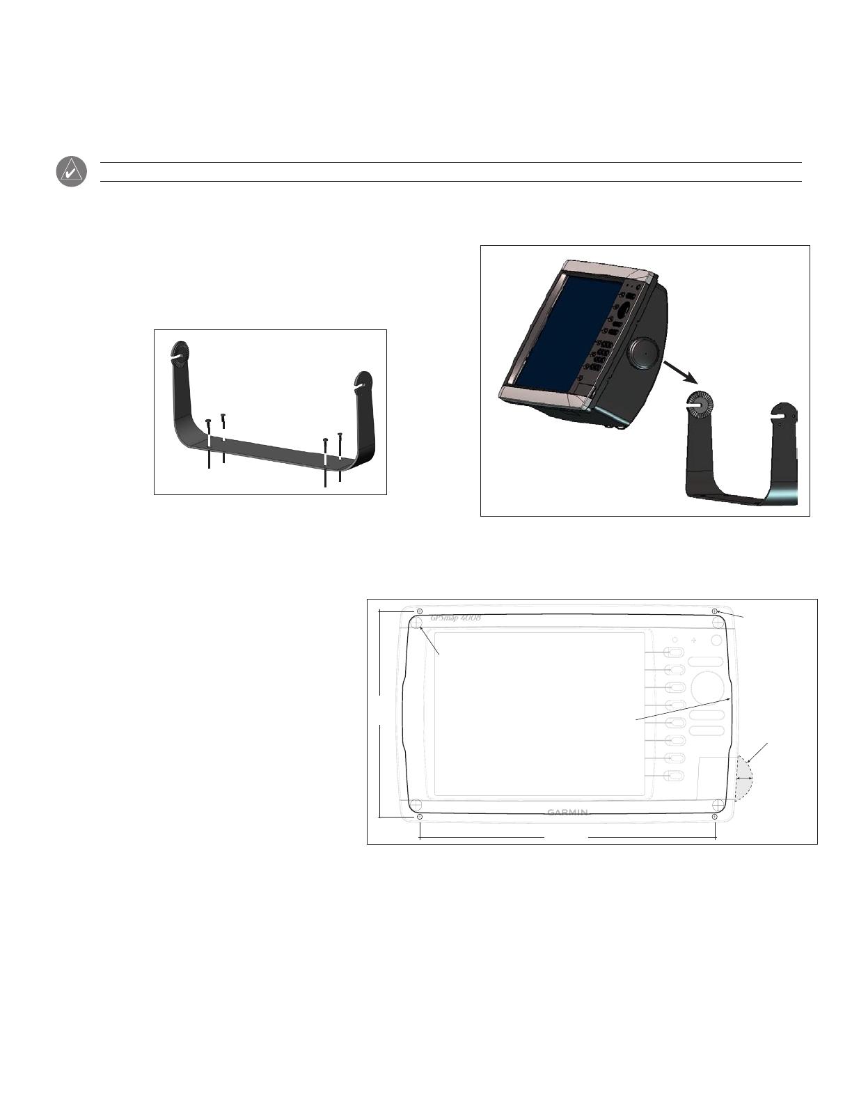
The mounting hardware (screws or nuts, washers, and bolts) are not included. The holes on the bail mount are
5
/
16
" (7.9 mm) in diameter.
Choose mounting hardware that ts the holes in the bail mount and best attaches it to your specic mounting surface. The size of the drill bit
required depends on the mounting hardware chosen.
July 2007 190-00779-02 Rev. C Printed in Taiwan
2 GPSMAP 4000/5000 Series Installation Instructions
To install the bail mount and unit:
1. Using the bail mount as a template, mark the location of the four mounting holes. Be sure to leave at least 5" (12.7 cm) of clearance
behind the unit for the wiring.
Mount a 4008/4208/5008/5208 unit 31
1
/
4
" (80 cm), and a 4012/4212/5012/5212 unit 39
3
/
8
"
from a magnetic compass to avoid interference.
2. Using an appropriately sized drill bit, drill the pilot holes for your mounting hardware.
3. Secure the bail mount to the surface with your mounting hardware.
4. Loosely attach the mounting knobs to the GPSMAP 4000/5000 series unit.
5. Slide the unit onto the bail mount, and tighten the mounting knobs.
Flush Mounting the GPSMAP 4000/5000 Series Unit
Hardware (included):
• Flush mount template
• Four threaded 4 mm mounting studs
• Four4mmatwashers
• Four 4 mm lock washers
• Four 4 mm nuts
Tools required (not included):
• Jig saw
• Masking tape
• Scissors
• Drill
• Drill bits—
3
/
8
" (6 mm) and 4 mm
•
1
/
16
" (2 mm) Allen (Hex) wrench
• 4 mm sockets or wrenches
• Center punch and hammer
July 2007 190-00779-03 Rev. B Printed in Taiwan
GPSMAP
®
4000 SERIES FLUSH MOUNT TEMPLATES
GPSMAP 4008/4208
USE 4 mm DRILL BIT
Pilot Hole
3/8" (9.5 mm)
6 17/32"
(165.90 mm)
9 5/8" (244.50 mm)
CUT ON
THIS LINE
Recommended clearance
for SD card door
1/2"
13 mm
Unit dimensions: 11 3/16" (284.4 mm) wide x 6 31/32" (176.9mm) high
190-00779-03_0B.indd 1 7/9/2007 10:08:51 AM
Flush Mount Template Example (not to scale)

3GPSMAP 4000/5000 Series Installation Instructions
To ush mount the unit:
1. Theushmounttemplateisincludedintheproductbox.Trimthetemplateandensureitwilltinthelocationyouwanttoushmountthe
unit.
Make sure the surface on which you mount the unit has at least 7" (17.75 cm) of open space behind it to t the unit and the connected
wires.
Make sure to leave approximately
1
/
2
" (13 mm) of space on the right side of the unit to access the SD card door.
Mount a 4008/4208/5008/5208 unit 31
1
/
4
" (80 cm), and a 4012/4212/5012/5212 unit 39
3
/
8
"
(1 m) from a magnetic compass to avoid
interference.
2. Theushmounttemplatehasadhesiveontheback.Removetheprotectivelinerandapplythetemplatetothelocationyouwanttomount
the unit.
3. Using the center punch, indent the center of each of the 4 mm mounting hole locations.
4. Using a 4 mm drill bit, drill the four mounting holes.
5. Using a
3
/
8
" (6 mm) drill bit, drill one or more of the four pilot holes inside the corner of the template to begin cutting the mounting surface.
6. Usingthejigsaw,cutthemountingsurfacealongtheinsideofthesolidlineindicatedontheushmounttemplate.Usealeand
sandpapertorenethesizeofthehole.Be very careful when cutting this hole. There is only a small amount of clearance between
the case and the mounting holes.
7. Install the four mounting studs into the unit by screwing the shorter, threaded section into the back of the unit. Use the
1
/
16
" (2 mm) Allen
wrench to tighten the mounting studs until they stop. Do not overtighten - you may damage the mounting stud or the mounting holes.
The studs are coated with a reusable thread-locking patch applied at the factory.
8. Place the unit into the cut-out. The four mounting studs should feed through the 4 mounting holes drilled in step 3.
9. Place the flat washers, then the lock washers over the mounting studs. Thread the hex nuts onto the mounting studs. Tighten all four hex
nuts evenly until the unit is snug against the mounting surface.
Flush Mounting the GPSMAP 4000/5000 Series Unit
4 GPSMAP 4000/5000 Series Installation Instructions
Mounting the GPS 17 Antenna
Either ush mount the GPS 17 Antenna or install it on on any standard 1" O. D.
14 threads-per-inch marine mount. When mounting the GPS 17, the cable can be
run externally, through the mounting surface, or through the center of the marine
mount.
The GPS 17 connects to the 19-pin NMEA 0183 cable on the GPSMAP
4000/5000 series unit and provides the GPS/WAAS signal to the unit. If two
or more Garmin Marine Network chartplotters are installed and connected to a
network, only install one GPS 17 antenna. See page 5 for wiring instructions.
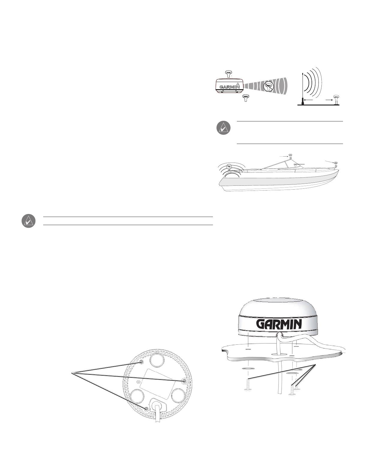
To ensure the best reception, mount the GPS 17 antenna in a location that has a
clear, unobstructed view of the sky in all directions. Avoid mounting the GPS 17
where it is shaded by the boat’s superstructure, a radome antenna, or mast. On
a sailboat, avoid mounting the antenna high on the mast to prevent inaccurate
speed readings caused by excessive heeling. The antenna provides more stable
readings when located nearer to water level.
Temporarily secure the antenna in the preferred mounting location and
test for correct operation. If you experience interference with other electronics, try
a different location. When you verify correct operation, permanently mount the
antenna.
Never paint the GPS 17 antenna or clean it with harsh solvents.
To ush mount the GPS 17:
1. Cut out the Flush Mount Drilling Template provided on page 11, and tape it on the selected mounting location.
2. Mark the center of each mounting hole by tapping the end of a center punch or pointed object with a hammer. If you plan to run the cable
through the mounting surface, mark the center of the additional, larger, hole indicated on the template.
3. Drill the mounting holes using a
11
/
64
" (4.5 mm) drill bit. If you plan to run the cable through the mounting surface, drill the hole using a
3
/
4
"
(19 mm) drill bit.
4. If you are routing the cable through the mounting surface feed it through the larger hole, and apply marine sealant to the outside exit
area.
5. Align the GPS 17 over the mounting holes, and fasten it using M4 screws (not
included). The mounting threads in the GPS 17 are 8.10 mm deep. Use screws
of a proper length for the mounting surface, which do not thread into the GPS
17 deeper than 8 mm. Screws which thread deeper than 8 mm may damage the
case.
Mounting holes
Bottom of GPS 17 Antenna
ABOVE - BEST
BELOW - OK
GPS Signal Interference
VHF Radio Antenna
SS BARNETT
EMI
GOOD
BEST
BETTER
Radar
EMI (Electromagnetic Interference)
from engine components
Mount the antenna at least 3 ft (1 m) away
from (preferably above) the path of any radar beam
or a VHF radio antenna.
3' (1 m)
ABOVE - BEST
BELOW - OK
GPS Signal Interference
VHF Radio Antenna
SS BARNETT
EMI
GOOD
BEST
BETTER
Radar
EMI (Electromagnetic Interference)
from engine components
Mount the antenna at least 3 ft (1 m) away
from (preferably above) the path of any radar beam
or a VHF radio antenna.
3' (1 m)
When installing the GPS 17, you can run the coax through
the mounting surface or outside of the unit. If the coax is run
through the mounting surface, seal the outside exit area with
marine sealant.
M4 screws
and washers
When installing the GPS 17, you can run the coax through
the mounting surface or outside of the unit. If the coax is run
through the mounting surface, seal the outside exit area with
marine sealant.
M4 screws
and washers
5GPSMAP 4000/5000 Series Installation Instructions
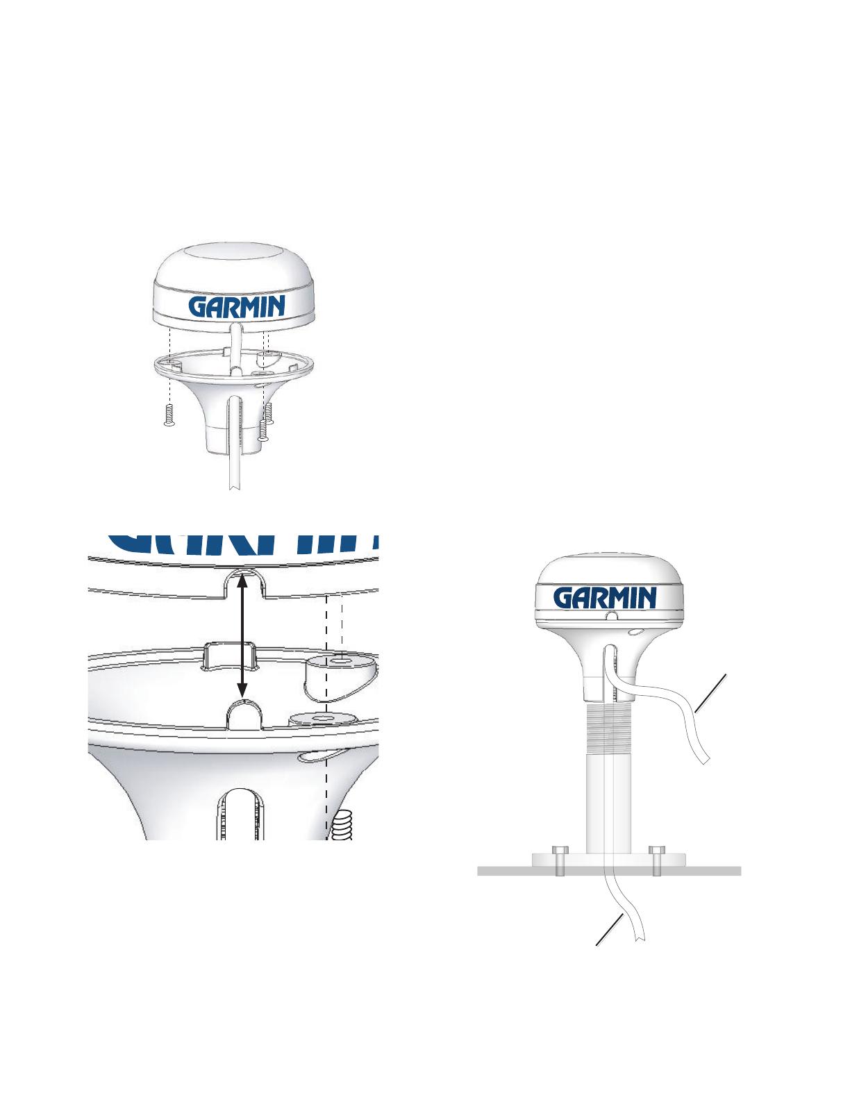
To attach the enclosed pole mount adapter to the GPS 17:
1. Thread the cable though the pole mount adapter.
2. Align the tab on the pole mount adapter to the notch on the
GPS 17.
3. Use the enclosed screws to secure the pole mount adapter to
the base of the GPS 17.
Attaching the Pole Mount Adapter to the GPS 17
Align Notch
To mount the GPS 17 with the cable run outside the
mount:
1. Place the cable in the vertical slot along the base of the
assembled GPS 17 and pole mount adapter.
2. Screw the assembled GPS 17 and pole mount adapter onto
a standard 1" O. D. 14 threads-per-inch marine mount (not
included). DO NOT overtighten the head. Overtightening the
unit may cut the cable.
3. WiththeGPS17installedonthepolemount,lltheremaining
gap in the cable exit with a marine sealant.
4. Fasten the pole mount to the boat if it is not already attached.
5. Routethecableawayfromsourcesofelectronicinterference.
To mount the GPS 17 with the cable run through the
mount:
1. Position a standard 1" O. D. (Outer Dimension), 14 threads-per-
inch marine mount (not included) in the preferred location, and
mark the approximate center of the mount.
2. Drill a hole using a
3
/
4
" (19 mm) drill bit for the cable to pass
through.
3.
Fasten the pole mount to the boat .
4. Slide the cable through the pole mount and screw the assembled
GPS 17 and pole mount adapter onto the pole mount.
5. Routethecableawayfromsourcesofelectronicinterference.
Cable run internally
Cable run externally
Attaching the GPS 17 to a Pole Mount
6 GPSMAP 4000/5000 Series Installation Instructions
Wiring and Cables
The GPSMAP 4000/5000 series unit comes with a power cable, a 19-pin NMEA 0183 data cable, and a 17-pin Marine Video cable. Optional
Garmin Marine Network components use specialized Garmin Network cables. Depending on the installation, it may be necessary to drill holes to
route the connector end of these cables. Garmin rubber grommets are provided to cover these holes for a nished look.
You may not need the grommets in some installations. The grommets do NOT
create a waterproof seal. Apply a marine sealant around the grommet and
cable after installation. Be sure to test the system before installing and sealing
the grommets. Purchase additional grommets from your Garmin dealer or
directly from Garmin at www.garmin.com.
Tools
Drill
1
1
/
4
" (31.7 mm) paddle drill bit or hole saw
Utility knife
Marine sealant (optional)
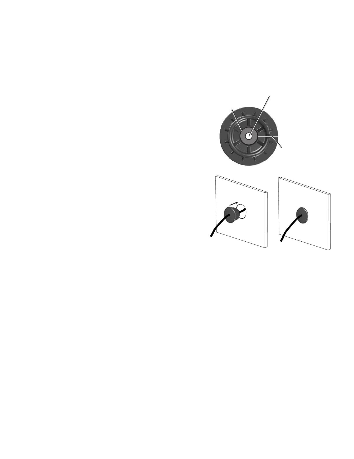
To install the cable grommet:
1. Mark the location where you want to route the power, NMEA 0183,
Marine Video, or Marine Network cable.
2. Using a 1
1
/
4
" (31.7 mm) paddle drill bit or hole saw, drill the installation hole.
3. Refertothediagramfortrimminginstructions.Carefullytrimthecableholein
the grommet, as needed.
4. Routethecabletotheunit,andtestthesystem.
5. Spread the grommet apart at the split and place it around the cable.
6. Firmly push the grommet into the installation hole until it is seated. Apply
marine sealant, as needed, to weatherproof the cable.
Wiring the Power Cable
The GPSMAP 4000/5000 series unit must be connected to the boat’s power supply. Use the 2-pin power cable included, and connect the power
(red) and ground (black) wires. Use 14 AWG shielded wiring for extended runs of wire to the power cable. Solder all connections and seal them
with heat shrink tubing.
Ensuring
•
•
•
•
Split
Use this hole (no trim) for the
power, NMEA, Marine Network,
or GPS 17 cable.
Trim to this line for
the Marine Video
cable.
Split
Use this hole (no trim) for the
power, NMEA, Marine Network,
or GPS 17 cable.
Trim to this line for
the Marine Video
cable.
7GPSMAP 4000/5000 Series Installation Instructions
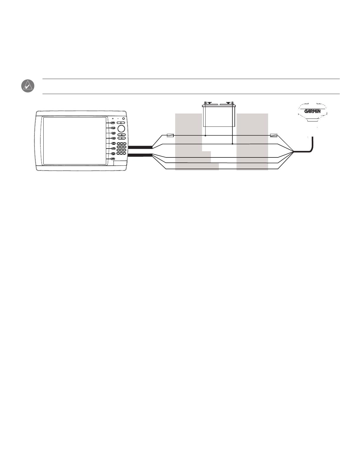
Wiring the GPS 17 Antenna
The GPS 17 antenna must be wired to the included 19-pin NMEA 0183 cable as well as to the boat’s power supply. Refer to the diagram below
when wiring the GPS 17 to the 19-pin NMEA 0183 cable. Use 22 AWG shielded wiring for extended runs of wire to the NMEA 0183 cable or
GPS 17 cable. Solder all connections and seal them with heat shrink tubing.
If you are using more than one Garmin chartplotter over a Garmin Marine Network, only wire one chartplotter to a GPS 17. The GPS
signal is shared between multiple chartplotters connected to a Garmin Marine Network.
Wiring the GPSMAP 4000/5000 Unit and the GPS 17
+
-
>
>
>
>
BATTERY
10-35 VDC
WIRE
COLOR
WIRE
COLOR
RED (POWER)
BLACK (GND)
ORANGE (ACC. ON)
GREEN (DATA OUT)
GREEN/WHITE (DATA IN)
RED (POWER)
BLACK (GND)
YELLOW (ON)
BLUE (DATA IN)
WHITE (DATA OUT)
FUSE
7.5A - 42V
FUSE
1 A
Garmin
GPSMAP 4000/5000
Series Unit
GPS 17
GPS/WAAS
Sensor
POWER
CABLE
NMEA 0183
CABLE
Wiring a Garmin Marine Network
The optional Garmin Marine Network is a plug-and-play system that allows for high-speed data transfer between multiple Garmin chartplotters
and other network compatible Garmin devices such as a Garmin sonar unit (GSD 22), a Garmin radar (GMR 18 or GMR 404/406), or an XM
Weather receiver (GDL30/30A). The GPSMAP 4000/5000 units have three network ports that can be used to connect other Garmin network
compatible chartplotters and devices. If the network requires more ports, use a Garmin Marine Network port extender (GMS 10), or another
GPSMAP 4000/5000. Data from each connected component is shared by all the connected Garmin chartplotters.
Notes:
• The GPS 17 antenna and standard NMEA devices must all be wired to one chartplotter on the network. The data is then shared over the
network to other connected chartplotters.
• Connectnetworkcomponents,suchasaGarminGMRradar,GSDsounder,orGDLXMWeatherreceivertoanychartplotteronthe
network or to an optional GMS 10 Network Port Expander. Data is shared between all chartplotters on the network.
• BlueChart
®
g2 Vision cartography data is shared between any connected GPSMAP 4000/5000 series chartplotter.
• Video input(s) from the Marine Video cable is only viewable on the chartplotter to which it is connected.
• You can connect a GPSMAP 4000/5000 chartplotter to a Marine Network with a GPSMAP 3000 series chartplotter:
They will share GPS 17 GPS position information as well as information to and from standard NMEA 0183 devices.
TheywillshareinformationfromconnectednetworkcompatibleGarmindevicessuchasasonarunit(GSD22),aradar(GMR18or
GMR404/406),oranXMWeatherreceiver(GDL30/30A).
Garmin GPSMAP 3000 series units CANNOT share cartography data with the GPSMAP 4000/5000 units.
• All network components must be connected to the boat’s power source according to their installation instructions. The following diagrams
show only the network connections, not power connections.
• Currently,XMWeatherandaudioserviceisonlyavailableinNorthAmerica.Becauseofthis,aconnectedXMWeatherreceiver(GDL30/
30A) will only function in North America.
•
•
•
8 GPSMAP 4000/5000 Series Installation Instructions
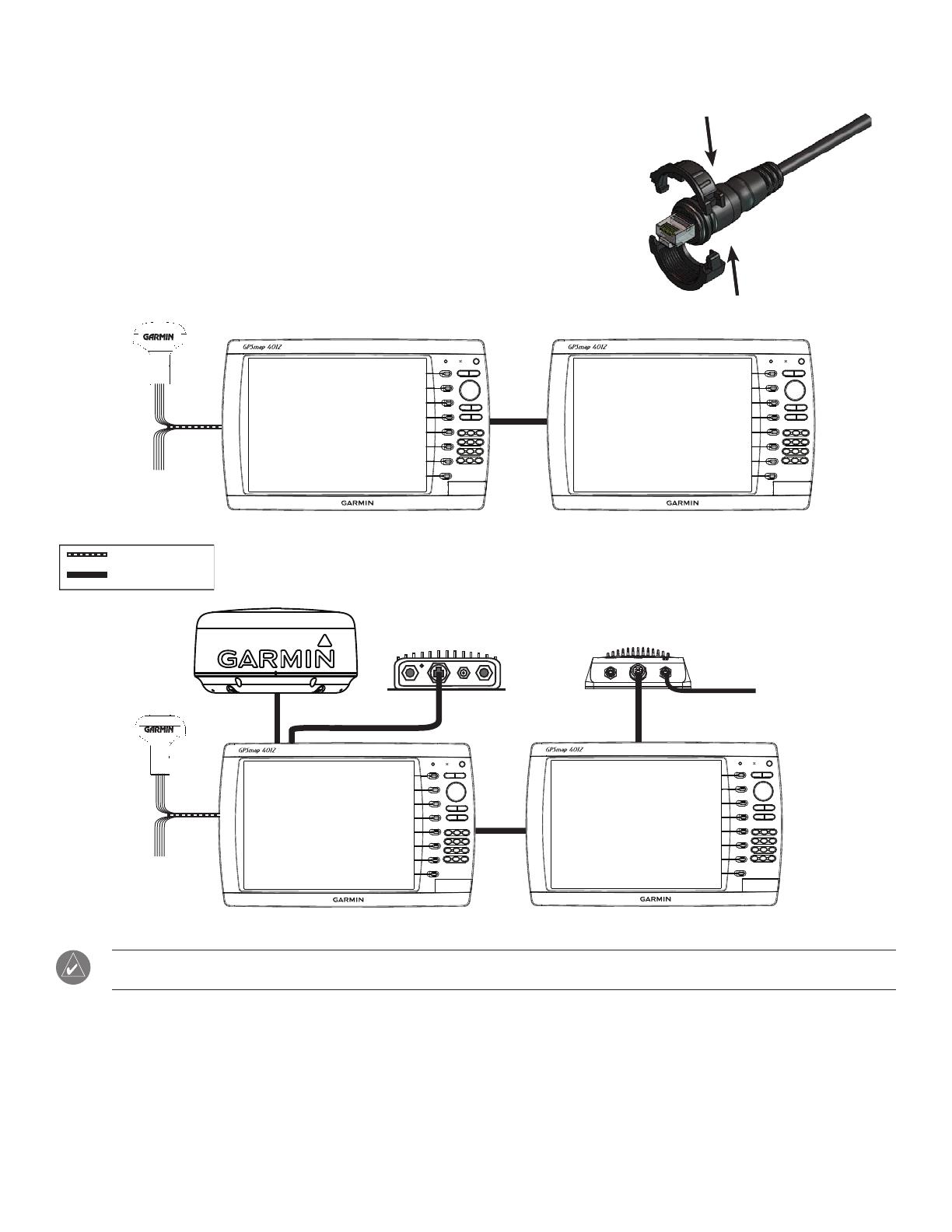
The Garmin Marine Network Cable:
• The Garmin Marine Network Cable has a locking ring that secures the cable to the
chartplotter or marine network device. Because of the size of this locking ring, it is not
connected to the network cable at the factory to make it easier to install on your boat.
• Once the cable is run to the chartplotter or network device, snap the locking ring together
around the connector and insert the rubber washer as indicated on the instructions
packaged with the cable.
Sample Garmin Marine Network Setups:
GPS 17
ADDITIONAL
NMEA
DEVICES
GARMIN GPSMAP 4000/5000
SERIES CHARTPLOTTER
GARMIN GPSMAP 4000/5000
SERIES CHARTPLOTTER
Marine Network with Two Chartplotters
Extended Marine Network With Two Chartplotters
x
x
x
x
x
x
x
x
xxxxxxx x x xx xxxxxxxx
GPS 17
ADDITIONAL
NMEA 0183
DEVICES
GARMIN GPSMAP 4000/5000
SERIES CHARTPLOTTER
GARMIN GPSMAP 4000/5000
SERIES CHARTPLOTTER
GARMIN MARINE RADAR
GSD 22 SOUNDER UNIT
TO TRANSDUCER
GDL 30/30A XM WEATHER UNIT
Every device connected to the Garmin Marine Network must be connected to the boat’s power supply. These diagrams only show the
network connections, and do not show the power connections. Wire each device according to its installation instructions.
NMEA 0183 CABLE
MARINE NETWORK
CABLE
NMEA 0183 CABLE
MARINE NETWORK
CABLE
9GPSMAP 4000/5000 Series Installation Instructions
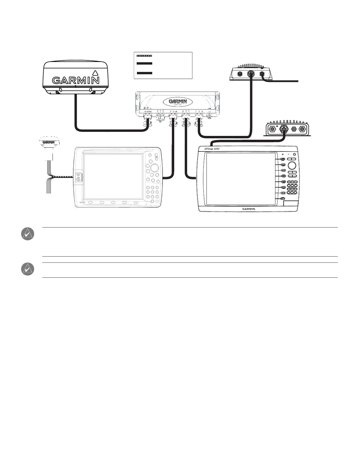
Connecting a GPSMAP 4000/5000 Series chartplotter to an existing Garmin Marine Network
x
x
x
x
x
x
x
x
xxxxxxxxxxxxxxxxxxx
GARMIN
GPSMAP 4000/5000 SERIES
CHARTPLOTTER
GSD 22 SOUNDER UNIT
TO TRANSDUCER
GPS 17
ADDITIONAL
NMEA 0183
DEVICES
GARMIN MARINE RADAR
GARMIN
GPSMAP 3000 SERIES
CHARTPLOTTER
GMS 10 MARINE NETWORK PORT EXPANDER
GDL 30/30A
XM WEATHER RECEIVER
When connecting a 4000/5000 series chartplotter to an existing Garmin Marine Network, the GMS 10 can be used, but is not necessary.
The 4000/5000 series chartplotter has three network ports, and acts as a port expander. Wire the GPS 17 and additional NMEA devices to either the
existing 3000 series chartplotter or the new 4000/5000 Series chartplotter. The existing 3000 series unit and the new 4000/5000 series unit share
NMEA 0183 and Garmin Marine Network data, but do not share cartography.
Every device connected to the Garmin Marine Network must be connected to the boat’s power supply. These diagrams only show the
network connections, and do not show the power connections. Wire each device according to its installation instructions.
NMEA 0183 CABLE
MARINE
NETWORK CABLE
TRANSDUCER
CABLE
xxxxxxxxx
NMEA 0183 CABLE
MARINE
NETWORK CABLE
TRANSDUCER
CABLE
xxxxxxxxx
10 GPSMAP 4000/5000 Series Installation Instructions
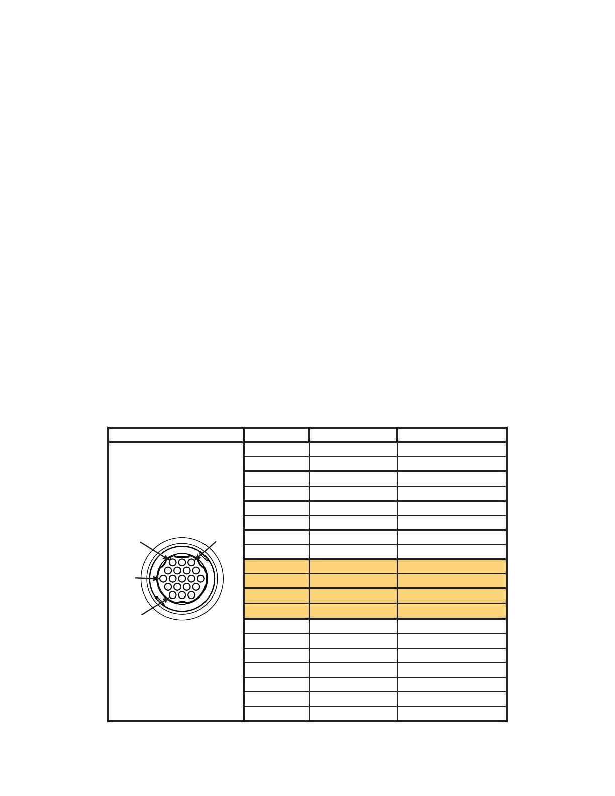
Wiring Additional NMEA 0183 Devices
The NMEA 0183 data cable included with the GPSMAP 4000/5000 series chartplotter supports the NMEA 0183 standard, which is used to wire
various NMEA 0183-compliant devices, such as VHF radios, NMEA instruments, autopilots, or a computer.
The GPSMAP 4000/5000 series unit features four ports to receive NMEA 0183 data (RX ports), and two ports to send NMEA 0183 data (TX
ports). Wire one NMEA 0183 device per RX port to send data to a 4000/5000 series unit, wire up to three NMEA 0183 devices in parallel to
each TX port to receive data from a 4000/5000 series unit.
Each RX and TX port has 2 wires, labeled A (+) and B (-) per the NMEA 0183 convention. Connect the corresponding A (+) and B (-) wires of
each port to the A (+) and B (-) wires of your NMEA 0183-compliant device. Refer to the table and wiring diagrams when wiring the 4000/5000
unit to NMEA 0183 devices.
Use 28 AWG, shielded, twisted pair wiring for extended runs of wire. Solder all connections and seal the
connection with heat shrink tubing.
Notes:
• For2-waycommunicationwithaNMEA0183device,theportsontheGPSMAP4000/5000unitsarenotlinked.Forexample,iftheRX
portoftheNMEA-compliantdeviceiswiredtoTXport1ontheGPSMAP4000/5000,youcanwiretheTXportofyourNMEA0183-
compliantdevicetoRXport1,port2,port3,orport4ontheGPSMAP4000/5000.
• The ground wires on the NMEA 0183 data cable from the GPSMAP 4000/5000 series unit and your NMEA 0183-compliant device must
both be grounded.
• ApprovedNMEA0183sentences—GPBWC,GPRMC,GPGGA,GPGSA,GPGSV,GPGLL,GPBOD,GPRMB,GPRTE,GPVTG,
GPWPL,GPXTE,andGarminproprietarysentences—PGRME,PGRMM,andPGRMZ.
• This unit also includes support for the WPL sentence, DSC, and sonar NMEA 0183 input with support for the DPT (depth) or DBT, MTW
(water temp), and VHW (water temp, speed, and heading) sentences.
• UsetheCommunicationssectionoftheConguremenuontheGPSMAP4000/5000seriesunittosetupNMEA0183communications.
See the owner’s manual for details.
Connector Pin Number Port Function Wire Color
1 RX PORT 1, A (+) WHITE
2 RX PORT 1, B (-) ORANGE/WHITE
5 RX PORT 2, A (+) BROWN
6 RX PORT 2, B (-) BROWN/WHITE
9 RX PORT 3, A (+) VIOLET
10 RX PORT 3, B (-) VIOLET/WHITE
11 RX PORT 4, A (+) BLACK/WHITE
12 RX PORT 4, B (-) RED/WHITE
3 TX PORT 1, A (+) GRAY
4 TX PORT 1, B (-) PINK
7 TX PORT 2, A (+) BLUE
8 TX PORT 2, B (-) BLUE/WHITE
13 GPS 17 IN GREEN/WHITE
14 GPS 17 OUT GREEN
15 SPARE
16 ALARM YELLOW
17 ACCESSORY ON ORANGE
18 GROUND BLACK
19 SPARE
NMEA 0183 Cable
End View
PIN 1
PIN 3
PIN 8
PIN 17
NMEA 0183 Cable
End View
PIN 1
PIN 3
PIN 8
PIN 17
11GPSMAP 4000/5000 Series Installation Instructions
GPSMAP 4000/5000 Series NMEA 0183 Data Cable
Wiring to a Standard NMEA 0183-compliant Device with 2-way Communication
+
-
>
>
>
>
>
>
>
>
Garmin
GPSMAP 4000/5000
Series Unit
NMEA 0183
Compliant Device
BATTERY
10-35 VDC
WIRE
SEE TABLE FOR
WIRE COLORS
WIRE
RED (POWER)
BLACK (PWR GND)
RED (POWER)
FUSE
7.5A - 42V
BLACK (DATA GND)
RX / A(+)
RX / B(-)
TX / A(+)
TX / B(-)
TX / A (+)
TX / B(-)
RX / A(+)
RX / B(-)
BLACK (PWR GND)
BLACK (DATA GND)
POWER
CABLE
NMEA 0183
CABLE
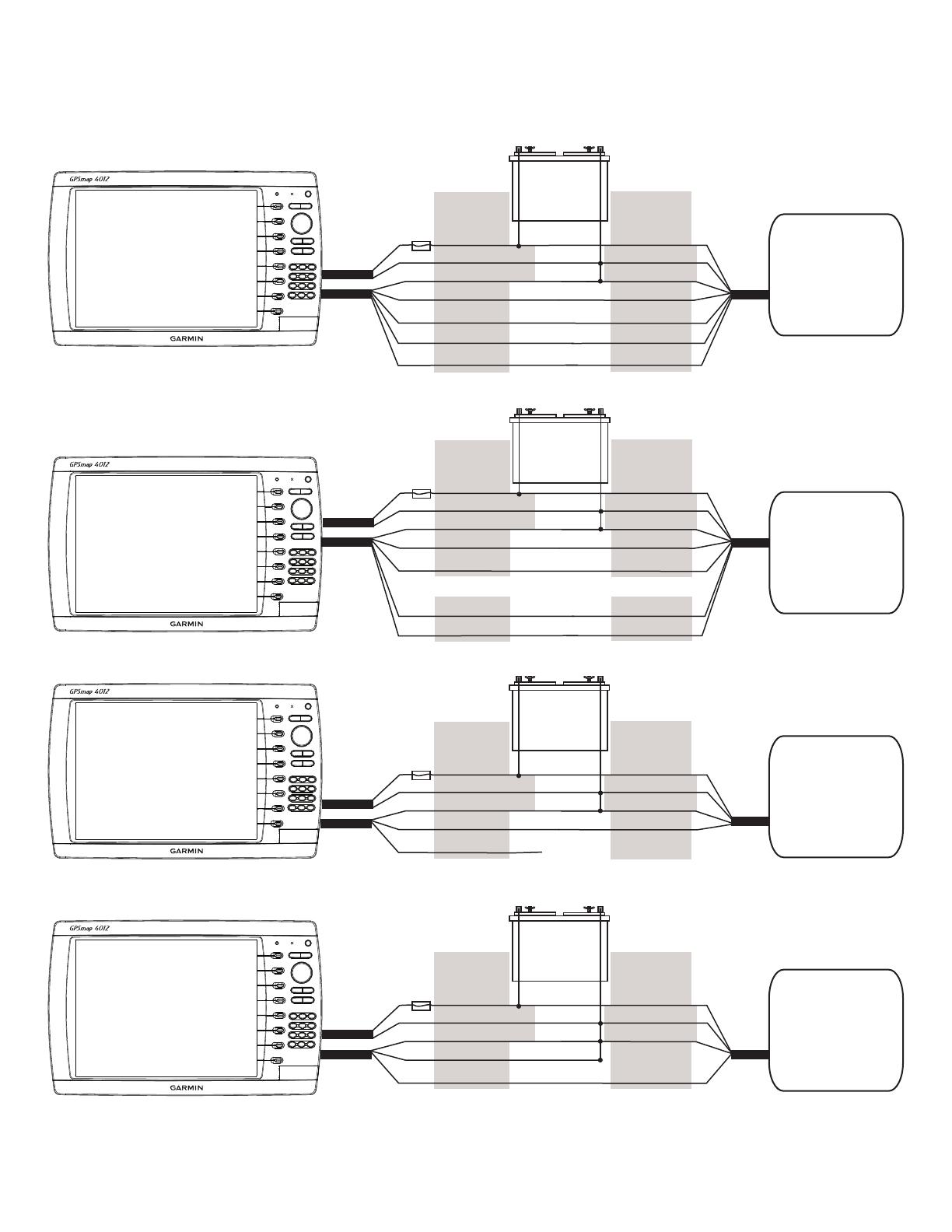
Wiring to a Standard NMEA 0183-compliant Device for One-Way Communication
+
-
>
>
>
>
>
>
>
>
Garmin
GPSMAP 4000/5000
Series Unit
NMEA 0183
Compliant Device
BATTERY
10-35 VDC
WIRE
SEE TABLE FOR
WIRE COLORS
WIRE
RED (POWER)
BLACK (PWR GND)
RED (POWER)
FUSE
7.5A - 42V
BLACK (DATA GND)
RX / A(+)
RX / B(-)
TX / A(+)
TX / B(-)
TX / A(+)
TX / B(-)
RX / A(+)
RX / B(-)
BLACK (PWR GND)
BLACK (DATA GND)
POWER
CABLE
NMEA 0183
CABLE
OR OR
Wiring to Send Data to a NMEA 0183-compliant Device With a Single Wire TX Connection
+
-
>
>
>
Garmin
GPSMAP 4000/5000
Series Unit
NMEA 0183
Compliant Device
BATTERY
10-35 VDC
WIRE
SEE TABLE FOR
WIRE COLORS
WIRE
RED (POWER)
BLACK (PWR GND)
RED (POWER)
FUSE
7.5A - 42V
BLACK (DATA GND)
TX / A(+)
TX / B(-)
RX
BLACK (PWR GND)
BLACK (DATA GND)
POWER
CABLE
NMEA 0183
CABLE
UNCONNECTED
Wiring to Receive Data from a NMEA 0183-compliant Device With a Single Wire RX Connection
+
-
>
>
>
Garmin
GPSMAP 4000/5000
Series Unit
NMEA 0183
Compliant Device
BATTERY
10-35 VDC
WIRE
SEE TABLE FOR
WIRE COLORS
WIRE
RED (POWER)
BLACK (PWR GND)
RED (POWER)
FUSE
7.5A - 42V
BLACK (DATA GND)
RX / B(-)
RX / A(+)
TX
BLACK (PWR GND)
BLACK (DATA GND)
POWER
CABLE
NMEA 0183
CABLE
12 GPSMAP 4000/5000 Series Installation Instructions
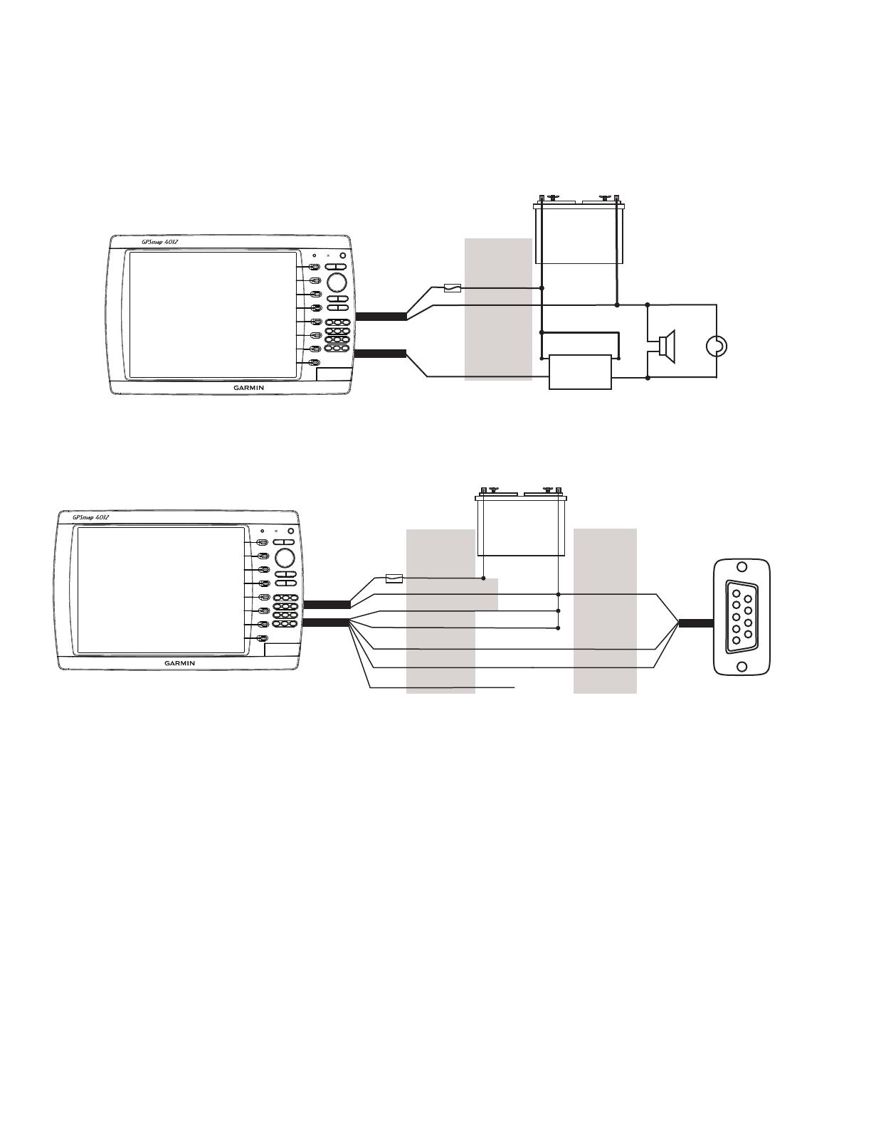
Wiring to an Optional Alarm
The GPSMAP 4000/5000 series unit can be used with a lamp, a horn, or both, to sound or ash an alert when the unit displays a message. The
alarm does not need to be wired for the 4000/5000 unit to function. The alarm circuit pulls low when the alarm sounds. The maximum current is
100 mA, and a relay is needed to limit the current from the unit to 100 mA. A switch can be installed to select between visual and audible alerts.
Wiring to a lamp, a horn, or both.
+
-
Garmin
GPSMAP 4000/5000
Series Unit
WIRE
COLOR
RED (POWER)
BLACK (GND)
YELLOW (ALARM)
BATTERY
10-35 VDC
RELAY
100 mA MAX
COIL CURRENT
HORN
LAMP
FUSE
7.5A - 42V
POWER
CABLE
NMEA 0183
CABLE
Wiring to a DB-9 PC Serial Connector
The GPSMAP 4000/5000 series unit can be connected to a PC with a serial port by wiring the unit to a DB-9 serial connector.
Wiring to a DB-9 Serial PC Connector
+
-
>
>
>
>
>
>
1
4
6
7
8
9
2
3
5
Garmin
GPSMAP 4000/5000
Series Unit
DB-9 Serial
PC Connector
BATTERY
10-35 VDC
WIRE
SEE TABLE FOR
WIRE COLORS
DB-9 PIN
NUMBERS
RED (POWER)
BLACK (PWR GND)
FUSE
7.5A - 42V
BLACK (DATA GND)
RX / B(-)
RX / A(+)
PIN 5: GND
PIN 3: TX
POWER
CABLE
NMEA 0183
CABLE
UNCONNECTED
PIN 2: RX
TX / B(+)
TX / A(-)
End View

13GPSMAP 4000/5000 Series Installation Instructions
Connecting to a NMEA 2000 Network
The GPSMAP 4000/5000 series unit is NMEA 2000 certied, and can receive data from a NMEA 2000 network installed on the boat to show
engine specic information on the Gauges section of the Information screen. Also, the unit can receive heading data from a heading sensor
connected to an installed NMEA 2000 network.
The 4000/5000 series unit features a male NMEA 2000 Micro-connector. Connect the unit to an installed NMEA 2000 network using a cable
with a female NMEA 2000 Micro connector on one end and the appropriate connector for the installed NMEA 2000 network on the other end.
NMEA 2000 cables are available from a local or online marine dealer.
NMEA 2000 Specications:
Load Equivalency Number (LEN) = 2
Unit Draw = 75 mA max
NMEA 2000 PGN information
The GPSMAP 4000/5000 series unit accepts the following PGN information from a NMEA 2000 network:
059392 = ISO acknowledgement
059904 = ISO request
060928 = ISO address Claim
126996 = Product information
127250 = Vessel heading
127488 = Engine parameters, rapid update (up to four engines)
127489 = Engine parameters, dynamic (up to four engines)
127505=Fluidlevel(0X00fuel-doesnotsupportotheruidtypes)
AllGPSMAP4000/5000seriesunitsareNMEA2000certied.
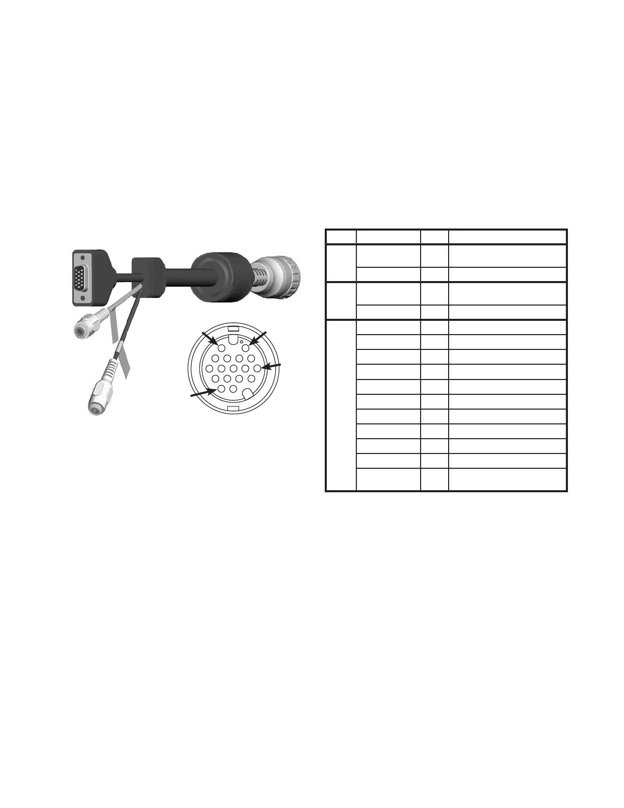
14 GPSMAP 4000/5000 Series Installation Instructions
Marine Video Cable
The included Marine Video 17-pin cable allows input of NTSC (National Television System Committee)/PAL (Phase Alternate Line) composite
video sources, and PC monitor output (4008/4208/5008/5208 = VGA output, 4012/4212/5012/5212 = XGA output). Marine Video inputs are
only available on the chartplotter to which they are attached and will not transmit over the Garmin Marine Network.
1 & 2.VIDEO1andVIDEO2Inputs(RCAconnectors)allowinputfromtwoseparateNTSC/PALcompatiblevideodevices,suchasVCR,
DVD, TV, or a video camera. The chartplotter can display one video input at a time or alternate between the two. See the Owner’s
Manual for details. Sound from a video source must be attached to a separate stereo/audio system. The video output from video device
attachestotheVideo1(BlackCable)orVideo2(GrayCable)RCAconnectors.
3. Use the PC monitor output (HD 15-pin) connector for remote viewing of the MFD display on a computer monitor. The remote monitor
must be capable of at least VGA resolution and have multi-sync capability.
Note Connector Pin Function
1 RCA-1
CENTER
2 VIDEO 1 IN (BLACK JACKET)
RCA-1 OUTER
6 VIDEO 1 IN, GND
2 RCA-2
CENTER
11 VIDEO 2 IN (GRAY JACKET)
RCA-2 OUTER
15 VIDEO 2 IN, GND
3 HD-15 PIN 1 1 VGA, ANALOG-RED
HD-15 PIN 2
4 VGA, ANALOG-GREEN
HD-15 PIN 3
3 VGA, ANALOG-BLUE
HD-15 PIN 5
13 VGA, ANALOG, GND
HD-15 PIN 6
8 VGA, ANALOG-RED, GND
HD-15 PIN 7
8 VGA, ANALOG-GREEN, GND
HD-15 PIN 8
8 VGA, ANALOG-BLUE, GND
HD-15 PIN 10
13 VGA, SYNC-GND
HD-15 PIN 13
7 VGA, H-SYNC
HD-15 PIN 14
12 VGA, V-SYNC
HD-15 PIN
SHELL
9 VGA, OVERALL SHIELD
1
3
2
PIN 1
PIN 2
PIN 7
PIN 17
1
3
2
PIN 1
PIN 2
PIN 7
PIN 17
Marine Video Cable
End View
Marine Video Cable
End View

15GPSMAP 4000/5000 Series Installation Instructions
Making the Final Connections to the GPSMAP 4000/5000 Unit
Once the power cable and the GPS 17 antenna (as well as any optional Garmin Marine Network devices, NMEA 0183 devices, NMEA 2000
connections, or video connections) have been wired to the boat, the cables must be connected to the GPSMAP 4000/5000 series unit.
There are seven connectors on the back of the unit, one for power, three for Garmin Marine Network devices, one for the NMEA 0183 cable,
one for a NMEA 2000 cable, and one for the marine video cable.
To attach the power cable, the NMEA 0183 cable, and the marine video cable, carefully press the cable into the correct port on the back of the
unit until it is rmly seated. Once the cable is seated, turn the locking ring clockwise
until it stops.
To attach a Garmin Marine Network cable or a NMEA 2000 Micro-connector cable, carefully press the cable into the correct port on the back of
the unit until it is rmly seated. . Once the cable is seated, turn the locking ring clockwise
until it is tight. Be careful not to overtighten.
Garmin Marine Network
connectors
Power cable connector
NMEA 0183 cable
connector
Marine video cable
connector
NMEA 2000 cable
Micro-connector
GPSMAP 4000/5000 Series Connectors

16 GPSMAP 4000/5000 Series Installation Instructions
Updating the Unit Software
Your GPSMAP 4000/5000 series unit may contain a software update SD card. If so, follow the instructions provided with the card.
If a software update SD card is not included, visit www.garmin.com to make sure your chartplotter software is up-to-date. To determine the
version of software on your unit, select or touch > >

17GPSMAP 4000/5000 Series Installation Instructions
GPS 17 Antenna Drilling Template
Drill this 3/4" (19 mm)
hole if the coax is going
to be installed through
the mounting panel.
Drill using a
11/64" (4.5 mm)
drill bit

© Copyright 2007 Garmin Ltd. or its subsidiaries
Garmin International, Inc.
1200 E 151st Street, Olathe, Kansas 66062 USA
Tel. 913/397.8200
Fax. 913/397.8282
Garmin (Europe) Ltd
Liberty House, Hounsdown Business Park, Southampton, Hampshire, SO40 9RB UK.
Tel. 44/0870.8501241 (outside the UK.) or 0808 2380000 (UK only)
Fax. 44/0870.8501251
Garmin Corporation
No. 68, Jangshu 2nd Road, Shijr, Taipei County, Taiwan
Tel. 886/2.2642.9199
Fax. 886/2.2642.9099
Part Number 190-00779-02 Rev. C
/