Page is loading ...

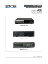
DX7000 Series
Digital Video Recorder
Installation/
Operation Manual
C682M-E (11/01)
®
Pelco • 3500 Pelco Way • Clovis, CA 93612-5699 USA • www.pelco.com
In North America and Canada: Tel (800) 289-9100 • FAX (800) 289-9150
International Customers: Tel +1(559) 292-1981 • FAX +1(559) 348-1120
00961

2 Pelco Manual C682M-E (11/01)
CONTENTS
IMPORTANT SAFEGUARDS AND WARNINGS ......................................................5
DESCRIPTION................................................................................................................6
MODELS ....................................................................................................................6
INSTALLATION..............................................................................................................7
TWO-WIRE CONTROL SYSTEM INSTALLATION ....................................................8
PROGRAMMING ............................................................................................................9
DISPLAY MODE ........................................................................................................9
DX7000 SYSTEM SETUP ........................................................................................10
CAMERA SETUP ..............................................................................................10
COLOR SETUP ................................................................................................11
SCHEDULE SETUP .........................................................................................12
SPEED SETUP .................................................................................................14
MOTION DETECTION SETUP .........................................................................15
PASSWORD SETUP ........................................................................................16
PAN & TILT SETUP...........................................................................................17
QUIT TO EXPLORER .......................................................................................17
UPDATE PROGRAM ........................................................................................17
OPERATION...................................................................................................................18
RECORDING STATUS .............................................................................................18
HDD STORAGE INDICATOR ...................................................................................18
VIEW .........................................................................................................................18
PTZ CONTROL MODE .............................................................................................18
PATTERN..........................................................................................................19
PRESETS .........................................................................................................19
PRESET TOURS ..............................................................................................20
SEARCH CONTROL MODE .....................................................................................21
SELECT DATE AND TIME................................................................................22
INDEX SEARCH ...............................................................................................22
BACKUP TO 3.5-INCH DISKETTE...................................................................23
PRINT IMAGE...................................................................................................23
CD-RW SEARCH......................................................................................................23
REMOTE VIEWING ..................................................................................................23
REMOTE SITE SOFTWARE .......................................................................................24
DESCRIPTION...............................................................................................................24
INSTALLATION.............................................................................................................24
REGISTERED SITE SETUP.....................................................................................25
OPERATION...................................................................................................................26
VIEW .........................................................................................................................28
PTZ CONTROL MODE .............................................................................................28
PATTERN..........................................................................................................29
PRESETS .........................................................................................................29
PRESET TOURS ..............................................................................................30
SEARCH MODE .......................................................................................................31
SELECT DATE AND TIME................................................................................32
EMERGENCY AGENT SOFTWARE.........................................................................33
BACKUP VIEWER SOFTWARE .................................................................................34
BACKUP VIEWER OPERATION................................................................................35
WATERMARKING TOOL .............................................................................................36
WATERMARKING TOOL OPERATION ....................................................................36

Pelco Manual C682M-E (11/01) 3
LIST OF TABLES
AVideo Coaxial Cable Requirements ...................................................................7
INSTALLING THE DX7000CD (CD-RW Drive) ......................................................38
LOADING THE DIRECTCD SOFTWARE .................................................................41
HOW TO OPERATE THE CD-RW ............................................................................41
INITIATE DX7000 COPY BUTTON...................................................................41
PREPARING CD-RW MEDIA FOR BACKUP ...........................................................42
INITIAL FORMATTING OF CD-RW MEDIA USING THE DX7000 DVR...........42
BACKUP WINDOW...................................................................................................44
HOW TO BACKUP (Copy) TO THE CD-RW DRIVE.........................................45
DX7000EM (External Modem) .................................................................................46
CONNECT THE EXTERNAL MODEM TO THE DX7000..........................................46
LOAD THE DRIVER FOR THE MODEM ..................................................................47
SPECIFICATIONS.........................................................................................................50
WARRANTY AND RETURN INFORMATION..........................................................52
LIST OF ILLUSTRATIONS
1 Rear View of Back Panel ...................................................................................7
2Two-Wire Control System Installation ................................................................8
3 PTZ Installation ..................................................................................................8
4 Power Adapter Plug for the RS-422 Converter Multiple.....................................8
5 Display Mode .....................................................................................................9
6 Channel Setup Menu ........................................................................................10
7 Color Setup Menu .............................................................................................11
8 Schedule Setup Menu.......................................................................................12
9 Speed Setup Menu ...........................................................................................14
10 Motion Detection Setup Menu...........................................................................15
11 Password Setup Menu ......................................................................................16
12 Pan and Tilt Protocol Menu ...............................................................................17
13 PTZ Controls .....................................................................................................18
14 PTZ Menus .......................................................................................................20
15 Search Control Menu ........................................................................................21
16 Playback Control Buttons..................................................................................22
17 DX7000 Series Remote User Software Installation Menu ................................24
18 Setup Screen ....................................................................................................25
19 Online Mode......................................................................................................26
20 PTZ Controls .....................................................................................................28
21 Pattern and Preset Bars....................................................................................30
22 Search Mode.....................................................................................................31
23 Playback Control Buttons..................................................................................32
24 Emergency Agent Window ................................................................................33
25 Backup Viewer ..................................................................................................35
26 The Image Has Not Been Altered .....................................................................36
27 The Image Has Been Altered ............................................................................37
28 How to Connect the CD-RW Drive to the DX7000 DVR ...................................38
29 Backup (COPY) Window...................................................................................44
30 Storage Indicator is now Labeled BACKUP ......................................................45
31 How to Connect the External Modem to the DX7000 DVR...............................46

4 Pelco Manual C682M-E (11/01)
(This page intentionally left blank.)

Pelco Manual C682M-E (11/01) 5
IMPORTANT SAFEGUARDS AND WARNINGS
Prior to installation and use of this product, the following WARNINGS should be observed.
1. Installation and servicing should only be done by qualified service personnel and con-
form to all local codes.
2. Unless the unit is specifically marked as a NEMA Type 3, 3R, 3S, 4, 4X ,6 or 6P en-
closure, it is designed for indoor use only and it must not be installed where exposed
to rain and moisture.
3. The installation method and materials should be capable of supporting four times the
weight of the unit and equipment.
The product and/or manual may bear the following marks:
Please thoroughly familiarize yourself with the information in this manual prior to installation
and operation.
This symbol indicates that dangerous volt-
age constituting a risk of electric shock is
present within this unit.
This symbol indicates that there are impor-
tant operating and maintenance instructions
in the literature accompanying this unit.
CAUTION:
RISK OF ELECTRIC SHOCK.
DO NOT OPEN.
NOTE: This equipment has been tested and found to comply with the limits of a Class B
digital device, pursuant to part 15 of the FCC rules. These limits are designed to provide
reasonable protection against harmful interference in a residential installation. This equip-
ment generates, uses, and can radiate radio frequency energy and, if not installed and
used in accordance with the instructions, may cause harmful interference to radio commu-
nications. However there is no guarantee that the interference will not occur in a particular
installation. If this equipment does cause harmful interference to radio or television recep-
tion, which can be determined by turning the equipment off and on, the user is encouraged
to try and correct the interference by one or more of the following measures:
• Reorient or relocate the receiving antenna.
• Increase the separation between the equipment and the receiver.
• Connect the equipment into an outlet on a circuit different from that to which the re-
ceiver is connected.
• Consult the dealer or an experienced radio/TV technician for help.
Connecting Power source to System Using 110V power source. Make sure power select
switch set to 115V(110V use)
Using 220V power source Make sure power select switch set to 230V(220V use)
NOTICE: For U.S.A and Canada regions; use only UL listed CSA labeled detachable
power cord, 3-conductor, 18 AWG, SVT or SJT type, plug rounding typeparallel blade,
cord connector body-IEC 320 style to mate with appliance inlet on product.
To reduce the risk of fire, use only No.26 AWG or larger telecommunications line cord.
IMPORTANT The only way to disconnect power completely is to unplug the power cord.
Make sure at least one end of the power cord is within easy reach so that you can unplug
the computer when you need to.
CAUTION: DANGER OF EXPLOSION IF BATTERY IS INCORRECTLY RE-
PLACED. REPLACE ONLY WITH THE SAME OR EQUIVALENT TYPE RECOM-
MENDED BY THE MANUFACTURER. DISCARD USED BATTERIES ACCORD-
ING TO THE MANUFACTURER’S INSTRUCTIONS.
ATTENTION: IL Y A DANGER D’EXPLOSION S’IL Y A REMPLACEMENT INCORRECT
DE LA BATTERIE. REMPLACER UNIQUEMENT AVEC UNE BATTERIE DU MENE TYPE
OU D’UN TYPE RECOMMANDE PAR LE CONSTRUCTEUR. METTRE AU REBUT LES
BATTERIES USAGEES CONFORMENENT AUX INSTRUCTIONS DU FABRICANT.

6 Pelco Manual C682M-E (11/01)
DESCRIPTION
The DX7000 Series are high-quality digital video recorders (DVR) that combine the functions
of a recorder and multiplexer into a product with versatile recording and playback functions.
The units are capable of dual operation and can record and play back video at the same time.
All models have an input signal of 120/230 VAC and are NTSC/PAL compatible.
MODELS
DX7008-030 Eight-channel digital video recorder, 30 GB hard drive space
DX7008-060 Eight-channel digital video recorder, 60 GB hard drive space
DX7008-120 Eight-channel digital video recorder, 120 GB hard drive space
DX7008-180 Eight-channel digital video recorder, 180 GB hard drive space
DX7008-240 Eight-channel digital video recorder, 240 GB hard drive space
DX7008-300 Eight-channel digital video recorder, 300 GB hard drive space
DX7008-360 Eight-channel digital video recorder, 360 GB hard drive space
DX7008-420 Eight-channel digital video recorder, 420 GB hard drive space
DX7008-480 Eight-channel digital video recorder, 480 GB hard drive space
DX7016-060 Sixteen-channel digital video recorder, 60 GB hard drive space
DX7016-120 Sixteen-channel digital video recorder, 120 GB hard drive space
DX7016-180 Sixteen-channel digital video recorder, 180 GB hard drive space
DX7016-240 Sixteen-channel digital video recorder, 240 GB hard drive space
DX7016-300 Sixteen-channel digital video recorder, 300 GB hard drive space
DX7016-360 Sixteen-channel digital video recorder, 360 GB hard drive space
DX7016-420 Sixteen-channel digital video recorder, 420 GB hard drive space
DX7016-480 Sixteen-channel digital video recorder, 480 GB hard drive space
The following accessories are supplied with the DX7000 Series DVR:
Qty Description
1 Keyboard
1 Mouse
1 RS-422 communication converter, includes power adapter
1 9-pin to 25-pin adapter
2 Power cables (1 USA standard and 1 European standard)
2 Keys for front panel
1 Microsoft Windows
®
98 CD
1 DX7000 Remote Site Software CD
4 Mounting screws
WARNING
This product is factory set to operate on 115 VAC.
For 230 VAC operation, move the switch to the 230 VAC
position
before applying power
to the unit.
01204

Pelco Manual C682M-E (11/01) 7
INSTALLATION
Place the DVR on any flat surface (desk or table) or install in any standard 19-inch (48.26 cm)
wide console or rack configuration.
Figure 1. Rear View of Back Panel
1 Camera Inputs – Refer to Table A for video coaxial cable distances.
2 Alarm Inputs
3 Analog Monitor Output
4 Relay Outputs
5 PC Monitor Output
6 LAN Port (Internet or TCP/IP)
7 NTSC/PAL Selection Switches – Setting must correspond with the software
setup for NTSC/PAL. Refer to Figure 6, item 2 .
8 Joystick Port (Not used)
9 Microphone Jack (Not used)
10 Audio IN/OUT (Not used)
11 COM 2 Serial Port – Connection for optional external modem.
12 Printer Port
13 COM 1 Serial Port – RS-422 two-wire control output; refer to Figure 2.
14 USB Connection – For optional USB device (CD-RW).
15 Keyboard (PS/2)
16 Mouse (PS/2)
17 AC Power Output
18 115/230 VAC Power Switch
19 AC Power Input
Table A. Video Coaxial Cable Requirements
Cable Type* Maximum Distance
RG59/U 750 ft (229 m)
RG6/U 1,000 ft (305 m)
RG11/U 1,500 ft (457 m)
* Minimum cable requirements:
75 ohms impedance
All-copper center conductor
All-copper braided shield with 95% braid coverage
00589
NOTE:
Set the PAL/NTSC
Switch to the proper setting
for your application. Refer to
7
.
NOTE:
An UPS (Uninter-
rupted Power Supply) is not
supplied with the DVR.
If required, Pelco recom-
mends a device with the
following specifications:
Capacity –
350 VA, 210 watts
Output voltage –
115 V
±
8% (on battery)
Frequency range –
47 Hz to 63 Hz

8 Pelco Manual C682M-E (11/01)
TWO-WIRE CONTROL SYSTEM INSTALLATION
1. Connect the control wires from the receiver to the RS-422 converter. The DX7000 can
support up to 16 PTZ devices. To connect more than one PTZ to the system, refer to
Figure 3.
RS-422 Converter Receiver
TX+ RX+
TX- RX-
2. Set the DTE/DCE switch located on the bottom of the converter to DCE.
3. Plug the RS-422 converter into the 9-pin to 25-pin adapter.
4. Plug the pin converter into the COM 1 Port.
5. Attach the power adapter to the RS-422 converter.
6. Plug power adapter into a power source. The standard European plug is attached to
the power adapter. To convert the adapter to the USA standard loosen the Phillips
head screw and remove the European plug (refer to Figure 4).
Figure 2. Two-Wire Control System Installation
Figure 4. Power Adapter Plug for the RS-422 Converter
NOTE:
The PTZ must be
set to accept ‘D’ protocol
control. For information on
setting the receiver address
for D-type control, refer to
the documentation supplied
with the PTZ equipment.
EUROPEAN STANDARD
ADAPTOR
PHILLIPS HEAD SCREW
USA STANDARD
00963
RXTX TX
-+-
RX RX TX TX
+-+-
RX RX TX TX
+-+-
PTZ
RX
+
PTZ
PTZ
THE LAST PTZ
TERMINATE
SUPPORTS UP TO 16 PTZ
MAXIMUM: 4,000 FEET (1,219 M)
01198
Figure 3. Multiple PTZ Installation
COM 1 PORT
PIN CONVERTER
RS-422 ADAPTER
BACK OF DX7000
POWER ADAPTER
01194

Pelco Manual C682M-E (11/01) 9
PROGRAMMING
Turn the system power ON; the Main Screen (DISPLAY mode) appears.
Figure 5. Display Mode
DISPLAY MODE
1 Date and Time Indicator – Displays current date and time.
2 SEARCH Button – Plays back and search recordings by date and time.
3 SETUP Button – Programs camera settings, customize a recording schedule, set
up multiple password levels, and establish pan and tilt protocol.
4 PTZ Control Button – Controls pan, tilt, and zoom functions. Sets patterns, tours,
and presets.
5 Copy Button (Backup) – Only appears if CD-RW software and CD-RW drive are
installed.
6 Exit – Closes DX7000 program.
7 HDD Storage Indicator – Displays percentage of used hard disk storage space.
8 Activate Relay – Turns connected relay ON/OFF.
9 Alarm Status Display – Turns button color yellow when an alarm has been activated.
10 Motion Detection Status – Turns button color blue, indicating motion is detected.
11 Screen Division
Single camera display Displays cameras 1-9
Quad display, cameras 1-4 Displays cameras 10-16
Quad display, cameras 5-8 Displays all 16 cameras
Quad display, cameras 9-12 Sequencing mode – Sequence us-
ing single, four, or nine camera dis-
plays.
Quad display, cameras 13-16 Full-screen display – Removes
menu bars from display. Click the
right mouse button to return to
previous screen display.
00582

10 Pelco Manual C682M-E (11/01)
DX7000 SYSTEM SETUP
To setup the DX7000 Digital Video Recorder use the left mouse button and click on the
SETUP button located in the DISPLAY mode.
CAMERA SETUP
Figure 6. Channel Setup Menu
1 CAMERA NAME Box
2 SIGNAL TYPE – Selection must correspond with the NTSC/PAL selection switch
setting. Refer to Figure 1, item 7 .
3 CAMERA ENABLE Button
4 CAMERA SELECTION Button
Use the following steps to set up a camera site.
1. Click the CAMERA ENABLE button to enable a camera for setup.
2. Click the CAMERA SELECTION button (located above the CAMERA ENABLE button);
the camera scene appears in the Camera Viewing Window.
3. Enter the location of the camera in the CAMERA NAME box.
1
2
3
4
01177

Pelco Manual C682M-E (11/01) 11
COLOR SETUP
Figure 7. Color Setup Menu
1 CON – Adjusts the CONTRAST of the viewed and recorded scene.
2 BRI – Adjusts the BRIGHTNESS of the viewed and recorded scene.
3 RED – Adjusts the RED level of the viewed and recorded scene.
4 GREEN – Adjusts the GREEN level of the viewed and recorded scene.
5 BLUE – Adjusts the BLUE level of the viewed and recorded scene.
6 DEFAULT COLOR – Return all level settings to their defaults.
7 Image Alignment Buttons – Moves the image up, down, left, and right within a
channel frame to align multi-screen images.
If required, adjust the level settings of the picture.
1. Select a camera by scrolling through the selections in the CHANNEL box.
2. Adjust the viewed image using the level settings.
3. Align image in the image frame using the Image Alignment buttons.
1
2
3
4
5
67
00959

12 Pelco Manual C682M-E (11/01)
SCHEDULE SETUP
Figure 8. Schedule Setup Menu
1 GROUP (01-24) – Selects group to be scheduled.
2 Sets START TIME and END TIME for recording group.
3 Schedule Selection Buttons
CLEAR ALL SCHEDULE – Clears all GROUP (1-24) schedules.
FULL RECORD – Adds all cameras and days to GROUP 1.
SENSOR TO CAMERA – Automatically selects the camera sensor for a GROUP in
a one-to-one ratio (Camera 1, Sensor 1, Group 1).
4 DAY OF WEEK – Selects the days of the week a selected GROUP will record.
5 CAMERA, MOTION, SENSOR, AND ALARM Buttons – Selects the camera,
recording triggers, and relay outputs for the selected GROUP.
6 REMOTE ALARM – Notifies remote site if alarm is triggered.
7 TARGET IP ADDRESS – Inputs address of remote site. Use with Emergency
Agent software.
8 AUTO REBOOT – Sets the day and time system will reboot.
9 GROUP INFORMATION – Lists schedule conflicts between groups.
3
4
6
5
9
8 7
1 2
01201

Pelco Manual C682M-E (11/01) 13
Evaluate the flow of motion at the surveillance site before programming a schedule. A record-
ing schedule can consist of one of the following modes and/or a combination of all modes:
NORMAL – Continuous recording recommended for surveillance areas with a
lot of movement.
MOTION – Saves disk space; records only when motion is detected.
SENSOR – Saves disk space; records only when an alarm is activated.
Example Schedule 1
Record 4 cameras with motion detection from Monday to Friday,
8:00 AM - 6:00 PM; Saturday 8:00 AM - 2:00 PM; and no recording on Sunday.
1. Select GROUP 01 and set START TIME to 8:00 and END TIME to 18:00.
2. Check MON, TUE, WED, THU, and FRI in the DAY OF WEEK section.
3. Select 01, 02, 03, and 04 in the CAMERA section.
4. Select 01, 02, 03, and 04 in MOTION section.
5. Select GROUP 02 and set the START TIME to 8:00 and END TIME to 14:00.
6. Check SAT in the DAY OF WEEK section.
7. Select 01, 02, 03, and 04 in CAMERA section.
8. Select 01, 02, 03, and 04 in MOTION section.
9. Select GROUP 03 and set END TIME at 8:00.
Example Schedule 2
Record continuously all week. When a signal input is received from sensor 1,
camera 1 starts recording and relay 1 starts operating. A signal input from
sensor 2 starts cameras 2 and 3 recording.
1. Select GROUP 01 and set START TIME to 0:00 and END TIME to 0:00.
2. Check SUN, MON, TUE, WED, THU, FRI, and SAT in the DAY OF WEEK
3. Select 01 in CAMERA and 01 in SENSOR and 01 in RELAY.
4. Select GROUP 02 and set START TIME to 0:00 and END TIME to 0:00.
5. Check SUN, MON, TUE, WED, THU, FRI, and SAT in the DAY OF WEEK.
6. Select 02 and 03 in CAMERA and 02 in SENSOR

14 Pelco Manual C682M-E (11/01)
SPEED SETUP
Figure 9. Speed Setup Menu
1 RECORDING SPEED MODE
a. NORMAL – Sets recording speed for continuous recording.
b. MOTION – Sets motion detection and pre-alarm recording speeds.
c. SENSOR – Sets sensor detection and pre-alarm recording speeds.
2 IMAGE QUALITY – Sets the compression size of the recorded image.
3 MOTION EXT. DURATION – Records time after motion is detected.
4 SENSOR EXT. DURATION – Records time after a sensor is triggered.
5 SWITCH SPEED – Sets the sequencing time between cameras connected to moni-
tor output.
6 WRITE INTERVAL – Determines how long images are stored in the buffer before
written to the hard drive.
7 BACKUP – Only available when backup device is installed.
8 DUPLEX MODE – Records and plays back recordings at the same time.
9 USE MODEM – Only available if modem is recognized.
10 RECORDING AND PRE-ALARM FUNCTION SPEEDS
a. Recording Speed: Controls the recording rate of each camera separately by ad-
justing the control bar for each individual camera. The total available fps for all
cameras varies per mode setup.
In Duplex Mode the maximum recording speed is 60 fps.
In Simplex Mode the maximum recording speed is 160 fps.
b. Pre- Alarm Function: You can program the pre-alarm function for motion and sen-
sor recording modes. When event (motion or sensor) is detected, images are re-
corded for the specific duration (5 seconds maximum per camera) before an
event happens.
11 A – Average recording rate for all cameras (1 through 16). All cameras record at the
same fps.
2
10
8 7
1
9
3
4
5
6
11
01203

Pelco Manual C682M-E (11/01) 15
MOTION DETECTION SETUP
Figure 10. Motion Detection Setup Menu
1 BEEP – Beeps when motion is detected.
2 SENSITIVITY – Adjusts the sensitivity of the detection areas.
3 CLEAR ALL BLOCK – Deletes all motion detection area blocks.
4 Motion Detection Area – To select a detection area move the pointer to the desired
area. Hold down the left mouse button and drag over the area. Release the left mouse
button to end selection. A maximum of 10 detection areas can be set per camera.
1
2
3
4
01192

16 Pelco Manual C682M-E (11/01)
PASSWORD SETUP
Figure 11. Password Setup Menu
1 SELECT LEVEL – Levels include Administrator, Search User, PTZ/Backup User, and
Client User.
2 INPUT AREA – Password input window.
3 NUMBER BUTTONS – Use number buttons to input password.
4 ENTER – Select to apply password to level.
5 CLEAR – Clears password input area.
To set a password:
1. Select the level.
2. Press the number buttons to input a password.
3. Click the ENTER button to apply the password input.
To clear a password:
1. Select the level.
2. Press the CLEAR button.
3. Click the ENTER button to apply the password input.
2
1
5
3
4
01195

Pelco Manual C682M-E (11/01) 17
PAN & TILT SETUP
Figure 12. Pan and Tilt Protocol Menu
1 Select pan and tilt protocol by scrolling through the selections in the RX TYPE box.
QUIT TO EXPLORER
The DX7000 uses a Window’s based operating system. To set a network address, add
hardware, or change clock settings click the Quit To Explorer button.
When exiting Windows Explorer the message “System will be shutdown” appears. Select
cancel to return to the DX7000 system DISPLAY mode.
Do not press OK. Selecting OK will turn the system off. To start the system:
1. Open the front panel of the DVR.
2. Press and hold the power switch down until the LED turns green.
IMPORTANT
Consult your network administrator to avoid possible network conflicts and to
obtain the information required to setup a network address.
UPDATE PROGRAM
To update system software click the Update Program button and follow the on-screen
instructions.
00964
1
01197

18 Pelco Manual C682M-E (11/01)
OPERATION
RECORDING STATUS
The colored circle located to the right of the on-screen camera title indicates the recording
status of the camera. RED indicates that the camera is recording continuously. If the circle
is BLUE, camera recording was triggered by motion detection. YELLOW indicates sensor
input recording, and a CLEAR circle means the camera is not currently recording.
HDD STORAGE INDICATOR
The DX7000 DVR automatically overwrites recorded data when the hard disk drive reaches
maximum storage capacity. When the HDD Storage Indicator displays 99%, the disk drive
is full. Recording continues by overwriting recorded data stored at the beginning of the HDD.
VIEW
It is not necessary to use the screen division buttons located in the lower left corner of the
screen to change the camera view. You can use the left and right mouse buttons to in-
stantly view a single camera or remove the menu bars from the display.
To change screen view:
1. Move the cursor to the desired camera view and click with the left mouse button.
A single view of the selected camera appears.
2. To switch to full screen view (remove menu bars from the display), click the right
mouse button on the screen. Click the right mouse button one more time to return to
the previous view.
3. Click the left mouse button to return to the multiple-screen view.
PTZ CONTROL MODE
To operate pan/tilt/zoom functions on controllable systems do the following:
1. Select a camera.
a. Move the cursor to a camera screen view and click the left mouse button.
b. A single camera view appears on the screen and the camera number (1 through 16)
appears in the center of the pan and tilt control (refer to Figure 13).
2. Use the buttons to pan left and right.
3. Use the buttons to tilt up and down.
4. If required use the FOCUS settings (+/-) to obtain the clearest picture.
5. Use the ZOOM settings (+/-) to zoom far/near.
Figure 13. PTZ Controls
▼
▲
▼
▲
DOWN
CAMERA
RIGHT
UP
LEFT
00949

Pelco Manual C682M-E (11/01) 19
PATTERN
A pattern is a user-defined, viewable camera path with a definite beginning and end.
The pattern can consist of any standard pan and tilt or lens commands. Once defined the
pattern is easily activated with the press of an on-screen menu button. The pattern will run
continuously until it is deactivated with another press of the menu button.
How to Program a Pattern
1. Click the PTZ button in the DISPLAY Mode. The PTZ Mode appears.
2. Select a camera.
3. Click on P-SET and move the camera through a series of movements using the pan
and tilt, zoom, and focus commands.
4. To stop programming the pattern, reclick the P-SET button.
5.
To run the pattern, click the P-RUN button. To stop the pattern, reclick the P-RUN button.
PRESETS
A preset is a user-defined camera position using pan and tilt, zoom, and focus commands.
The DX7000 Series DVR has programming capacity for 12 preset locations.
How to Program A Preset
1. Click the PTZ button in the DISPLAY Mode. The PTZ Mode appears.
2. Click the left mouse button on PRESET.
3. Select a camera by moving the cursor to the desired camera view and clicking the left
mouse button.
4. Move the camera to a desired position.
3. Click the SET button to turn it ON.
5. Click a preset button 1-12. To continue setting presets move the camera and click an-
other preset button.
6. Click the SET button to stop programming preset positions.
NOTE:
The selected camera is indicated by the number displayed in the center of
the PTZ controls.
How to Move to a Preset
1. Click the MOVE button.
2. Click a preset button 1-12. The camera moves to the programmed preset position.
How to Clear a Preset
1. Click the CLEAR button.
2. Click a preset button 1-12.

20 Pelco Manual C682M-E (11/01)
PRESET TOURS
A preset tour is a programmed sequential execution of preset positions.
How to Program a Preset Tour
1. Click the PTZ button in the DISPLAY Mode. The PTZ Mode appears.
2. Click the left mouse button on PRESET.
3. Select a camera by moving the cursor to the desired camera view and clicking the left
mouse button.
4. Click the TOUR button to turn it ON.
3. Click the SET button to turn it ON.
5. Click preset buttons in any sequential order to program a tour.
6. To stop programming the preset tour, click the SET button and then the TOUR button.
How to Run A Preset Tour
1. Click the PTZ button in the DISPLAY Mode. The PTZ Mode appears.
2. Click the left mouse button on PRESET.
3. Click the TOUR button.
4. Click the MOVE button, the preset tour starts.
5. To stop the tour click the MOVE and TOUR buttons.
How to Clear a Preset Tour
1. Click the TOUR button.
2. Click the CLEAR button. The preset tour is now cleared. A preset tour must be cleared
before a new preset tour can be programmed.
Figure 14. PTZ Menus
FOR
FUTURE
USE
PRESET
BUTTONS
CAMERA
01193
/