Bunker Hill Security 91309 User manual

Category
Camera kits
Type
User manual
UNDERWATER CAMERA
WITH MONITOR
ASSEMBLY AND OPERATING INSTRUCTIONS
3491 Mission Oaks Blvd., Camarillo, CA 93011
Visit our Web site at http://www.harborfreight.com
Copyright
©
2004 by Harbor Freight Tools
®
. All rights reserved. No portion
of this manual or any artwork contained herein may be reproduced in any shape
or form without the express written consent of Harbor Freight Tools.
For technical questions and replacement parts, please call 1-800-444-3353
91309
®
Page 2SKU 91309 For technical questions, please call 1-800-444-3353.
Save This Manual
You will need the manual for the safety warnings and precautions, assembly instructions,
operating and maintenance procedures, parts list and diagram. Keep your invoice with this
manual. Write the invoice number on the inside of the front cover. Keep the manual and
invoice in a safe and dry place for future reference.
General Safety Warnings and Precautions
WARNING: When using product, basic safety precautions should always be followed to
reduce the risk of personal injury and damage to equipment.
Read all instructions before using this product!
1. Keep work area clean. Cluttered areas invite injuries.
2. Observe work area conditions. Do not use the Battery (4) or Monitor (2) in damp or
wet locations. Don’t expose them to rain. Keep work area well lit.
3. Keep children away. Do not let them handle the Camera/Monitor system.
4. Store idle equipment. When not in use, the Camera/Monitor system must be stored
in a dry location to inhibit rust. Always lock up the Camera/Monitor system and keep
it out of reach of children.
5. Use the right product for the job. There are certain applications for which this
product was designed. Do not modify this product and do not use this product for a
purpose for which it was not intended.
6. Dress properly. Do not wear loose clothing or jewelry as they can be caught in
cables. Protective, electrically non-conductive clothes and non-skid footwear are
recommended when working. Wear restrictive hair covering to contain long hair.
7. Use eye protection. Always wear ANSI approved impact safety goggles during
setup, maintenance, and whenever handling the Battery (4). If working near water,
wear a life vest and use other appropriate safety gear, if necessary.
8. Do not overreach. Keep proper footing and balance at all times.
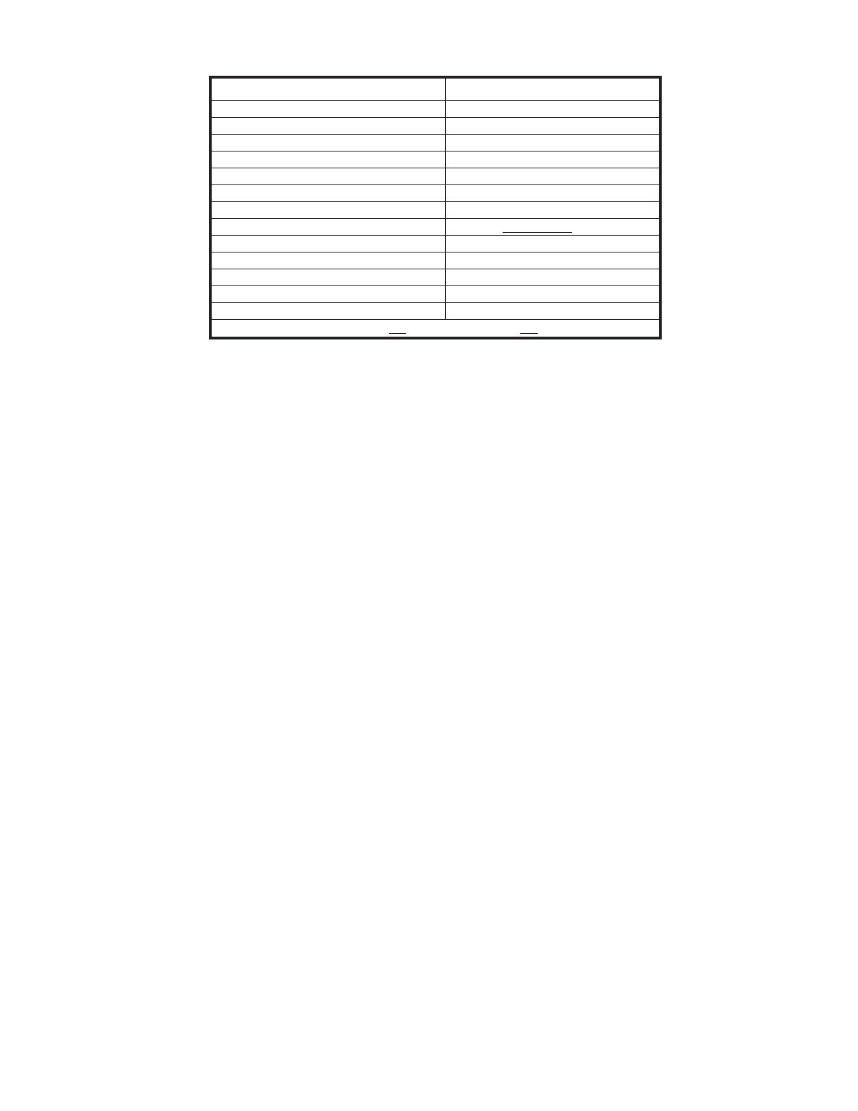
Specifications
Battery Sealed, Lead Acid (with fuse)
Maximum Camera Depth 65 Feet (Length of Cable)
Overall Weight 11.85 Lbs.
Camera Dimensions 1-5/8” W x 7” L x 3-7/8” H
Camera Light Source Built-in Infrared LED Bulbs
Input Voltage 12 Volts DC
Camera Operating Temperature -20° to 120° F
Camera Angle-of-View 83° (horizontal), 60° (vertical)
Camera Depth-of-View 15” (approximate; in clear water)
Monitor Image Black and White
Monitor Picture Resolution 450 (TV Lines)
Monitor Input Voltage 11 to 15 Volts DC
Monitor Operating Temperature -20° to 120° F
Monitor Dimensions 6-1/16” W x 7-5/8” L x 6” H
*Note: Battery and Monitor not water-resistant and not for underwater use.
REV 03/05
Page 3SKU 91309 For technical questions, please call 1-800-444-3353.
9. Maintain products with care. Keep products clean for better and safer performance.
Follow instructions for changing accessories. Inspect cords periodically, and if
damaged, have them repaired by an authorized technician.
10. Disconnect power. Unplug the system when not in use.
11. Stay alert. Watch what you are doing, use common sense. Do not operate any
product when you are tired.
12. Check for damaged parts. Before using any product, any part that appears
damaged should be carefully checked to determine that it will operate properly and
perform its intended function. Check for any broken parts or mounting fixtures, a
leaking battery, loose connections, damaged seals on the Camera, and any other
condition that may affect proper operation. Any part that is damaged should be
properly repaired or replaced by a qualified technician. Do not use the product if any
switch does not turn On and Off properly.
13. Replacement parts and accessories. When servicing, use only identical
replacement parts. Use of any other parts will void the warranty. Only use accessories
intended for use with this product. Approved accessories are available from Harbor
Freight Tools.
14. Do not operate product if under the influence of alcohol or drugs. Read warning
labels if taking prescription medicine to determine if your judgment or reflexes are
impaired while taking drugs. If there is any doubt, do not operate the product.
15. Maintenance. For your safety, service and maintenance should be performed
regularly by a qualified technician.
16. Pacemaker Warning. People with pacemakers should consult their physician(s)
before using this product. Electromagnetic fields in close proximity to a heart
pacemaker could cause interference to or failure of the pacemaker.
Note: Performance of this product may vary depending on battery power.
Warning: The warnings, cautions, and instructions discussed in this instruction manual
cannot cover all possible conditions and situations that may occur. It must be under-
stood by the operator that common sense and caution are factors which cannot be
built into this product, but must be supplied by the operator.
Unpacking
When unpacking, check to make sure the parts listed on page 7 are included. If any parts
are missing or broken, please call Harbor Freight Tools at the number on the cover of this
manual as soon as possible.
Page 4SKU 91309 For technical questions, please call 1-800-444-3353.
Monitor and Underwater Camera Specific Safety Warnings
1. Keep the Monitor (2) out of the direct sunlight. Do not let it overheat, freeze, or be
exposed to wet conditions.
2. Do not locate the Monitor (2) near radiators, ovens, or any other heat source.
3. Always handle the Monitor (2) and the Camera (1) with care. Do not allow either to
experience shaking or strong vibration. Never use the Camera in surf, near a pier, rocks,
or any other obstacle.
4. To allow air circulation, locate the Monitor (2) at least two inches from walls, cabinets, or
other enclosures.
5. When connecting the Camera (1) to the Monitor (2), the power must be off or both
units will be damaged.
6. Do not tip or drop the Battery (4). Tipping or dropping will cause acid to leak. If
acid leaks on you, immediately wash off the acid with cold water. Seek medical
attention immediately.
7. Always keep the RED (+) terminal on the Battery (4) disconnected unless the system is
being used. When connected, it will constantly drain the Battery (4).
Operation
Connecting the system
Note: This is a 12 Volt DC system and will not work on 24 Volt DC systems; hooking
the monitor up to a 24V system can damage or ruin this product.
Rear Inputs shown in FIGURE 1:
DC 12 Volt In - Plug in 12 VDC power system here.
VCR Camera - When the switch is set on “VCR”, you can record footage to a VCR. When
the switch is on “Camera”, It will show the footage being captured by the Camera.
Video Out - to be used to record to a VCR.
Video In - Can be used as a video-only monitor (no sound).
C1 - Camera connection.
C2 - Second camera connection.
DC 12 Volt In
VCR Camera
Video In
C1
Video Out
C2
FIGURE 1
FIGURE 2
Battery
Cord (5)
Battery (4)
Camera (1)
Monitor (2)
65 Foot Cable (3)
Page 5SKU 91309 For technical questions, please call 1-800-444-3353.
Connecting the system (continued)
Operation (continued)
1. Set the Monitor (2) in a dry, stable position, out of the direct sunlight and in accordance with
the operational warnings above. Set the Sunshade (8) on top of the Monitor (2). Just a few
feet from the Camera (1), run the 65 Foot Cable (3) around a railing or post to keep the
weight of the Camera (1) from dislodging the Monitor (2) from its stable position. Plug the
65 Foot Cable (3) into the Camera port (C1) on the back of the Monitor (2). Refer to
FIGURE 2 on page 4,
2. Set the Battery (4) in a dry position, on a plate or other flat, stable surface out of the sun,
close enough for the Battery Cord (5) to reach the rear of the Monitor (2). Attach the Black
(-) alligator clip on the Battery Cord (5) to the Black (-) terminal on the Battery (4). Attach
the Red (+) alligator clip on the Battery Cord (5) to the Red (+) terminal on the Battery (4).
Plug the other end of the Battery Cord (5) into the DC 12 Volt In input on the back of the
Monitor (2).
3. Set the VCR/Camera switch (on the back of the Monitor (2)) to Camera.
4. Turn on the POWER button on the front of the Monitor (2). See FIGURE 3 below.
FIGURE 3
5. Push the Camera button (above) in, if using the C1 Camera input, and leave it out if using
the C2 input. You should see an image on the Monitor (2).
If not, recheck your connections.
Note: The Ballast (see FIGURE 4) can be
set so that the Camera (1) can be set to
have no angle, or angled slightly down
or up. Slightly open the bracket on
the Camera (1) to tilt the Ballast.
6. Gently lower the Camera into the wa-
ter and reel out the 65 Foot Cable (3)
until it is at the appropriate depth.
7. Adjust the Brightness (BRI.) and Contrast
(CONT.) on the front of the Monitor (2). See
FIGURE 3. If additional light is needed, push on the (LED) switch on the front of the
Monitor (2). You can dim the LED lights with the DIMMER switch.
8. When you are finished, remove the Camera (1) from the water, turn off the POWER switch
on the Monitor (2), disconnect the alligator clips on the Battery Cord (5) from the Battery
(4), and unplug the Battery Cord (5) from the Monitor (2).
Warning!! Always keep the Camera (1) and Battery (4) dry and protected from the
elements. Never try to disassemble the Camera’s (1) waterproof housing.
FIGURE 4
Camera (1)
Bracket
Ballast
Page 6SKU 91309 For technical questions, please call 1-800-444-3353.
Maintenance
(-) Negative
(+) Positive
FIGURE 5
1. Always turn off the power and disconnect the unit when not in use.
2. Wipe all of the components to remove any moisture after each use.
3. Make sure the terminal contacts on the Battery (4) are clean and free of corrosion.
4. After six hours of use, charge the Battery (4) following the directions below.
5. Keep the Camera (1) lens clear of dirt or debris.
Battery Charging
Connect the two clips of the Charger (7) to the corresponding positive and negative terminals
on the Battery (4). Plug the Charger (7) plug into the power outlet. The indicator on the
Charger (7) will stay red until the charge is complete. Once the charge is complete, the
indicator will turn green. Promptly unplug the unit from the power outlet and remove the clips
from the terminals. Do not overcharge the battery; overcharging can result in damage to
or acid leaking from the battery.
Never reverse the polarity when connecting the Battery (4) for charging it or running
the system. The Red (+) terminal must be attached to the Red (+) clip on the Battery Cord
(5), and the Black (-) terminal must be attached to the Black (-) clip. See FIGURE 5.
Troubleshooting
If the system is not operating properly, by displaying a rolling, shrunk, or unstable picture,
check all of the connections. Next, make sure the Battery (4) is fully charged. Also, check to
make sure the fuse on the Battery (4) is good. If the system still does not work properly, take
the system to an authorized service technician.
Battery (4)
Adapter (7)
Page 7SKU 91309 For technical questions, please call 1-800-444-3353.
NOTE: Some parts are listed and shown for illustration purposes only and are not available
individually as replacement parts.
PLEASE READ THE FOLLOWING CAREFULLY
THE MANUFACTURER AND/OR DISTRIBUTOR HAS PROVIDED THE PARTS DIAGRAM
IN THIS MANUAL AS A REFERENCE TOOL ONLY. NEITHER THE MANUFACTURER NOR
DISTRIBUTOR MAKES ANY REPRESENTATION OR WARRANTY OF ANY KIND TO THE BUYER
THAT HE OR SHE IS QUALIFIED TO MAKE ANY REPAIRS TO THE PRODUCT OR THAT HE OR
SHE IS QUALIFIED TO REPLACE ANY PARTS OF THE PRODUCT. IN FACT, THE MANUFAC-
TURER AND/OR DISTRIBUTOR EXPRESSLY STATES THAT ALL REPAIRS AND PARTS RE-
PLACEMENTS SHOULD BE UNDERTAKEN BY CERTIFIED AND LICENSED TECHNICIANS
AND NOT BY THE BUYER. THE BUYER ASSUMES ALL RISK AND LIABILITY ARISING OUT OF
HIS OR HER REPAIRS TO THE ORIGINAL PRODUCT OR REPLACEMENT PARTS THERETO,
OR ARISING OUT OF HIS OR HER INSTALLATION OF REPLACEMENT PARTS THERETO.
1
2
3
4
5
6
Assembly Drawing and Parts List
Note: Adapter (7) and Sunshade (8) not shown.
Part No. Description
1 Camera
2 Monitor
3 65 Foot Cable (attached to Camera (1))
4 Battery
5 Battery Cord
6 Case
7 Adapter
8 Sunshade
  • Page 1 1
  • Page 2 2
  • Page 3 3
  • Page 4 4
  • Page 5 5
  • Page 6 6
  • Page 7 7

Bunker Hill Security 91309 User manual

Category
Camera kits
Type
User manual

Ask a question and I''ll find the answer in the document

Finding information in a document is now easier with AI