Samsung WS28V55VS8XXEC User manual
- Category
- CRT TVs
- Type
- User manual
This manual is also suitable for

COLOR TELEVISION RECEIVER
Chassis : KS3A(P)_50Hz(REV. 4)
Model : WS28V53NS8XXEC
WS28V55VS8XXEC
WS32V56VS8XXEC
COLOR TELEVISION RECEIVER CONTENTS
Precautions
Reference Information
Specifications
Alignment and Adjustments
Troubleshooting
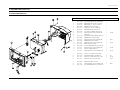
Exploded Views and Parts List
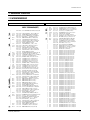
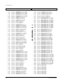
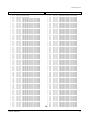
Electrical Parts List
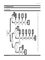
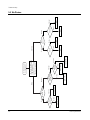
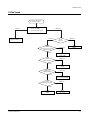
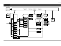
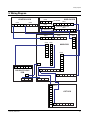
Block Diagrams
Wiring Diagram
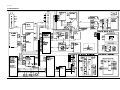
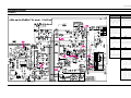
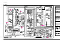
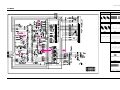
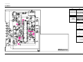
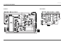
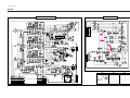
Schematic Diagrams
1.
2.
3.
4.
5.
6.
7.
8.
9.
10.

1. Precautions
1-1 Safety Precautions
1. Be sure that all of the built-in protective
devices are replaced. Restore any missing
protective shields.
2. When reinstalling the chassis and its
assemblies, be sure to restore all protective
devices, including: nonmetallic control knobs
and compartment covers.
3. Make sure that there are no cabinet openings
through which people—particularly
children—might insert fingers and contact
dangerous voltages. Such openings include
the spacing between the picture tube and the
cabinet mask, excessively wide cabinet
ventilation slots, and improperly fitted back
covers.
If the measured resistance is less than 1.0
megohm or greater than 5.2 megohms, an
abnormality exists that must be corrected
before the unit is returned to the customer.
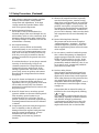
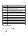
4. Leakage Current Hot Check (Figure 1-1):
Warning: Do not use an isolation
transformer during this test. Use a leakage-
current tester or a metering system that
complies with American National Standards
Institute (ANIS C101.1, Leakage Current for
Appliances), and Underwriters Laboratories
(UL Publication UL1410, 59.7).
5. With the unit completely reassembled, plug
the AC line cord directly into the power
outlet. With the unit’s AC switch first in the
ON position and then OFF, measure the
current between a known earth ground (metal
water pipe, conduit, etc.) and all exposed
metal parts, including: antennas, handle
brackets, metal cabinets, screwheads and
control shafts. The current measured should
not exceed 0.5 milliamp. Reverse the power-
plug prongs in the AC outlet and repeat the
test.
Fig. 1-1 AC Leakage Test
6. Antenna Cold Check:
With the unit’s AC plug disconnected from the
AC source, connect an electrical jumper across
the two AC prongs. Connect one lead of the
ohmmeter to an AC prong. Connect the other
lead to the coaxial connector.
7. X-ray Limits:
The picture tube is especially designed to
prohibit X-ray emissions. To ensure continued
X-ray protection, replace the picture tube only
with one that is the same type as the original.
Carefully reinstall the picture tube shields and
mounting hardware; these also provide X-ray
protection.
8. High Voltage Limits:
High voltage must be measured each time
servicing is done on the B+, horizontal
deflection or high voltage circuits.
Correct operation of the X-ray protection
circuits must be reconfirmed whenever they
are serviced.
(X-ray protection circuits also may be called
“horizontal disable” or “hold-down”.)
Heed the high voltage limits. These include
the X–ray Protection Specifications Label, and
the Product Safety and X-ray Warning Note on
the service data schematic.
Precautions
Samsung Electronics 1-1
LEAKAGE
CURRENT
TESTER
DEVICE
UNDER
TEST
TEST ALL
EXPOSED METAL
SURFACES
2-WIRE CORD
ALSO TEST WITH
PLUG REVERSED
(USING AC ADAPTER
PLUG AS REQUIRED)
EARTH
GROUND
(READING SHOULD
NOT BE ABOVE
0.5mA)
Follow these safety, servicing and ESD precautions to prevent damage and protect against potential
hazards such as electrical shock and X-rays.

1-1 Safety Precautions (Continued)
9. High voltage is maintained within specified
limits by close-tolerance, safety-related
components and adjustments. If the high
voltage exceeds the specified limits, check
each of the special components.
10. Design Alteration Warning:
Never alter or add to the mechanical or
electrical design of this unit. Example: Do not
add auxiliary audio or video connectors. Such
alterations might create a safety hazard. Also,
any design changes or additions will void the
manufacturer’s warranty.
11. Hot Chassis Warning:
Some TV receiver chassis are electrically
connected directly to one conductor of the AC
power cord. If an isolation transformer is not
used, these units may be safely serviced only
if the AC power plug is inserted so that the
chassis is connected to the ground side of the
AC source.
To confirm that the AC power plug is inserted
correctly, do the following: Using an AC
voltmeter, measure the voltage between the
chassis and a known earth ground. If the
reading is greater than 1.0V, remove the AC
power plug, reverse its polarity and reinsert.
Re-measure the voltage between the chassis
and ground.
12. Some TV chassis are designed to operate with
85 volts AC between chassis and ground,
regardless of the AC plug polarity. These units
can be safely serviced only if an isolation
transformer inserted between the receiver and
the power source.
13. Some TV chassis have a secondary ground
system in addition to the main chassis ground.
This secondary ground system is not
isolated from the AC power line. The two
ground systems are electrically separated by
insulating material that must not be defeated
or altered.
14. Components, parts and wiring that appear to
have overheated or that are otherwise
damaged should be replaced with parts that
meet the original specifications. Always
determine the cause of damage or
overheating, and correct any potential
hazards.
15. Observe the original lead dress, especially
near the following areas: Antenna wiring,
sharp edges, and especially the AC and high
voltage power supplies. Always inspect for
pinched, out-of-place, or frayed wiring. Do
not change the spacing between components
and the printed circuit board. Check the AC
power cord for damage. Make sure that leads
and components do not touch thermally hot
parts.
16. Picture Tube Implosion Warning:
The picture tube in this receiver employs
“integral implosion” protection. To ensure
continued implosion protection, make sure
that the replacement picture tube is the same
as the original.
17. Do not remove, install or handle the picture
tube without first putting on shatterproof
goggles equipped with side shields. Never
handle the picture tube by its neck. Some
“in-line” picture tubes are equipped with a
permanently attached deflection yoke; do not
try to remove such “permanently attached”
yokes from the picture tube.
18. Product Safety Notice:
Some electrical and mechanical parts have
special safety-related characteristics which
might not be obvious from visual inspection.
These safety features and the protection they
give might be lost if the replacement
component differs from the original—even if
the replacement is rated for higher voltage,
wattage, etc.
Components that are critical for safety are
indicated in the circuit diagram by shading,
( ) or ( ).
Use replacement components that have the
same ratings, especially for flame resistance
and dielectric strength specifications.
A replacement part that does not have the
same safety characteristics as the original
might create shock, fire or other hazards.
Precautions
1-2 Samsung Electronics
!

1-2 Servicing Precautions
1. Servicing precautions are printed on the
cabinet. Follow them.
2. Always unplug the unit’s AC power cord from
the AC power source before attempting to:
(a) Remove or reinstall any component or
assembly, (b) Disconnect an electrical plug or
connector, (c) Connect a test component in
parallel with an electrolytic capacitor.
3. Some components are raised above the printed
circuit board for safety. An insulation tube or
tape is sometimes used. The internal wiring is
sometimes clamped to prevent contact with
thermally hot components. Reinstall all such
elements to their original position.
4. After servicing, always check that the screws,
components and wiring have been correctly
reinstalled. Make sure that the portion around
the serviced part has not been damaged.
5. Check the insulation between the blades of the
AC plug and accessible conductive parts
(examples: metal panels, input terminals and
earphone jacks).
6. Insulation Checking Procedure: Disconnect the
power cord from the AC source and turn the
power switch ON. Connect an insulation
resistance meter (500V) to the blades of the AC
plug.
The insulation resistance between each blade
of the AC plug and accessible conductive parts
(see above) should be greater than 1 megohm.
7. Never defeat any of the B+ voltage interlocks.
Do not apply AC power to the unit (or any of
its assemblies) unless all solid-state heat sinks
are correctly installed.
8. Always connect a test instrument’s ground
lead to the instrument chassis ground before
connecting the positive lead; always remove
the instrument’s ground lead last.
Precautions
Samsung Electronics 1-3
Warning1: First read the “Safety Precautions” section of this manual. If some unforeseen circumstance creates a conflict between
the servicing and safety precautions, always follow the safety precautions.
Warning2: An electrolytic capacitor installed with the wrong polarity might explode.

1. Some semiconductor (“solid state”) devices
are easily damaged by static electricity. Such
components are called Electrostatically
Sensitive Devices (ESDs); examples include
integrated circuits and some field-effect
transistors. The following techniques will
reduce the occurrence of component damage
caused by static electricity.
2. Immediately before handling any semicon
ductor components or assemblies, drain the
electrostatic charge from your body by
touching a known earth ground. Alternatively,
wear a discharging wrist-strap device. (Be
sure to remove it prior to applying power—
this is an electric shock precaution.)
3. After removing an ESD-equipped assembly,
place it on a conductive surface such as
aluminum foil to prevent accumulation of
electrostatic charge.
4. Do not use freon-propelled chemicals. These
can generate electrical charges that damage
ESDs.
5. Use only a grounded-tip soldering iron when
soldering or unsoldering ESDs.
6. Use only an anti-static solder removal device.
Many solder removal devices are not rated as
“anti-static”; these can accumulate sufficient
electrical charge to damage ESDs.
7. Do not remove a replacement ESD from its
protective package until you are ready to
install it. Most replacement ESDs are
packaged with leads that are electrically
shorted together by conductive foam,
aluminum foil or other conductive materials.
8. Immediately before removing the protective
material from the leads of a replacement ESD,
touch the protective material to the chassis or
circuit assembly into which the device will be
installed.
9. Minimize body motions when handling
unpackaged replacement ESDs. Motions such
as brushing clothes together, or lifting a foot
from a carpeted floor can generate enough
static electricity to damage an ESD.
Precautions
1-4 Samsung Electronics
1-3 Precautions for Electrostatically Sensitive Devices (ESDs)

Reference Information
Samsung Electronics 2-1
2. Reference Information
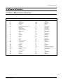
2-1 Tables of Abbreviations and Acronyms
A
Ah
Å
dB
dBm
°C
°F
°K
F
G
GHz
g
H
Hz
h
ips
kWh
kg
kHz
kΩ
km
km/h
kV
kVA
kW
I
MHz
Ampere
Ampere-hour
Angstrom
Decibel
Decibel Referenced to One
Milliwatt
Degree Celsius
Degree Fahrenheit
degree Kelvin
Farad
Gauss
Gigahertz
Gram
Henry
Hertz
Hour
Inches Per Second
Kilowatt-hour
Kilogram
Kilohertz
Kilohm
Kilometer
Kilometer Per Hour
Kilovolt
Kilovolt-ampere
Kilowatt
Liter
Megahertz
MV
MW
MΩ
m
µA
µF
µH
µm
µs
µW
mA
mg
mH
mI
mm
ms
mV
nF
Ω
pF
Ib
rpm
rps
s
V
VA
W
Wh
Megavolt
Megawatt
Megohm
Meter
Microampere
Microfarad
Microhenry
Micrometer
Microsecond
Microwatt
Milliampere
Milligram
Millihenry
Milliliter
Millimeter
Millisecond
Millivolt
Nanofarad
Ohm
Picofarad
Pound
Revolutions Per Minute
Revolutions Per Second
Second (Time)
Volt
Volt-ampere
Watt
Watt-hour
Table 2-1 Abbreviations

Reference Information
2-2 Samsung Electronics
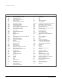
Table 2-2 Table of Acronyms
ABL
AC
ACC
AF
AFC
AFT
AGC
AM
ANSI
APC
APC
A/V
AVC
BAL
BPF
B-Y
CATV
CB
CCD
CCTV
Ch
CRT
CW
DC
DVM
EIA
ESD
ESD
FBP
FBT
FF
FM
FS
GND
G-Y
H
HF
HI-FI
IC
IC
IF
Automatic Brightness Limiter
Alternating Current
Automatic Chroma Control
Audio Frequency
Automatic Frequency Control
Automatic Fine Tuning
Automatic Gain Control
Amplitude Modulation
American National Standards Institute
Automatic Phase Control
Automatic Picture Control
Audio-Video
Automatic Volume Control
Balance
Bandpass Filter
Blue-Y
Community Antenna Television (Cable TV)
Citizens Band
Charge Coupled Device
Closed Circuit Television
Channel
Cathode Ray Tube
Continuous Wave
Direct Current
Digital Volt Meter
Electronics Industries Association
Electrostatic Discharge
Electrostatically Sensitive Device
Feedback Pulse
Flyback Transformer
Flip-Flop
Frequency Modulation
Fail Safe
Ground
Green-Y
High
High-Frequency
High Fidelity
Inductance-Capacitance
Integrated Circuit
Intermediate Frequency
I/O
L
L
LED
LF
MOSFET
MTS
NAB
NEC
NTSC
OSD
PCB
PLL
PWM
QIF
R
RC
RF
R-Y
SAP
SAW
SIF
SMPS
S/N
SW
TP
TTL
TV
UHF
UL
UV
VCD
VCO
VCXO
VHF
VIF
VR
VTR
VTVM
TR
Input/output
Left
Low
Light Emitting Diode
Low Frequency
Metal-Oxide-Semiconductor-Field-Effect-Tr
Multi-channel Television Sound
National Association of Broadcasters
National Electric Code
National Television Systems Committee
On Screen Display
Printed Circuit Board
Phase-Locked Loop
Pulse Width Modulation
Quadrature Intermediate Frequency
Right
Resistor & Capacitor
Radio Frequency
Red-Y
Second Audio Program
Surface Acoustic Wave(Filter)
Sound Intermediate Frequency
Switching Mode Power Supply
Signal/Noise
Switch
Test Point
Transistor Transistor Logic
Television
Ultra High Frequency
Underwriters Laboratories
Ultraviolet
Variable-Capacitance Diode
Voltage Controlled Oscillator
Voltage Controlled Crystal Oscillator
Very High Frequency
Video Intermediate Frequency
Variable Resistor
Video Tape Recorder
Vacuum Tube Voltmeter
Transistor

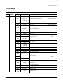
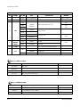
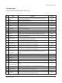
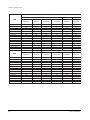
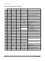
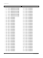
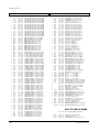
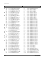
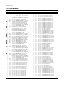
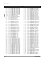
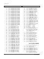
Table 2 - 3 IC Line - Up
NO
1
DESCRIPTION
Video Processor
Multistandard Sound Processor
MICOM, TTX(MTP)
EEPROM
Audio AMP
RGB Drive AMP Hybrid IC
Vertical IC
Horizontal Drive IC
E/W Drive IC
SPS Controllor
Bridge Diode
Photo Coupler
5V Controlled Regulator
Rectifier Diode
3.3V Regulator
6V Regulator
8V Controlled Regulator
3.3V Regulator
MICOM Reset IC
IIC Level Shifter
Reference Information
Samsung Electronics 2-3
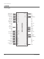
2-2 IC Line Up
LOC. NO
IC201S
IC601
IC901
IC902
IC602
HIC201
HIC202
HIC203
HIC204
IC301
Q402
Q401
D414
IC401
Q404
IC801S
D801S
PC801S
IC802
D805
D806
D807
D802
IC201
IC804
IC803
IC903
IC904
Q909
Q910
BOARD
MAIN
SPEC
VDP3130Y
MSP3411G
SDA555X
KS24L161
TDA7297
DRGB001
LA7845
KSC2073-H2
KSD5703
FMP-3FU
KA393
IRF620
3S1265RB
3S1265RD
RBV606
PC123Y
KA78R05
FML-G12S
FMG-G2CS
KA78RM33
KA7806
KA78R08
KA78RM33
KIA7025AP
2N700
REMARK
Refer to Table 2-3-1
Refer to Table 2-3-2
Refer to Table 2-3-3
VM Option
HC401
HC801

2-4 Samsung Electronics
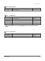
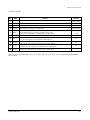
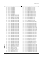
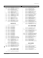
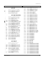
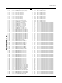
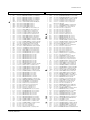
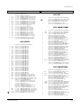
Table 2 - 3 IC Line - Up
NO
2
3
4
5
DESCRIPTION
Video Output AMP R.G.B Drive
Push-Pull (VM)
TR-Power (TILT)
OP-AMP (TILT)
OP-AMP
TR-Power
Video Switching IC with Adder Output
High-end Picture-In Picture IC
1-TUNER PIP
3.3V Regulator
LOC. NO
TU01S
TU02S
IC501
IC502
IC503
QF04
QF05
QG02
QG03
ICG01
ICH01
QH01
ICS01
ICP01
ICP02
SPEC
TCL3101PD09A9(S)
TCL3101PD09A9(S)
TDA5109
TDA6101Q
2SC2344
2SA1011
KSA940
KSD2073-H2
KA4558
KA4558
2SC4636RB
TEA6425
SDA9489X
SDA9489
EZ1086CM
REMARK
Refer to Table 2-3-4
Refer to Table 2-3-5
FLAT
FLAT
FLAT
Option
Option
Option
Option
Option
Option
BOARD
CRT
DOUBLE
FOCUS
V-S/W
PIP
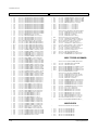
Reference Information
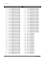
SPEC
VDP3108B
VDP3112B
VDP3120B
VDP3130Y
FUNCTION
50Hz Basic
50Hz, 2H Comb Filter
50Hz, 2H Comb Filter, Horizontal Scaler
50Hz, 2H Comb Filter, DVD Input
REMARK
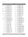
Table 2-3-1 VIDEO IC (IC201S)
SPEC
MSP3400D
MSP3410D
MSP3411G
FUNCTION
Multistandard, A2 Stereo
Multistandard, A2 Stereo, Nicam
Multistandard, A2 Stereo, Nicam, Vitual Dolby
REMARK
Table 2-3-2 SOUND IC (IC601)

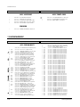
Reference Information
Samsung Electronics 2-5
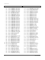
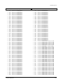
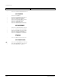
SPEC
TDA7297
FUNCTION
15W x 2CH, 10W x 2CH
REMARK
SPEC
TCLS3101PD09A(S)
TCPS3000P
TCPS3001PD09E(S)
TCPW3001PD09A(S)
TCL3101PD16A
FUNCTION
CS with LNA Function
CS
CS
CZ, CW
CS
REMARK
Main(Old)
India
Main(New)
SPEC
TCPS3000PC09B(S)
TCPS3000PC16B
FUNCTION
CS
CS
REMARK
Sub(Old()
Sub(New)
TCPS3001PD09A(S) is out-of-date, TCPS3001PD09D(S) which is up-to-date has the same function.
Table 2-3-3 SOUND AMP (IC602)
Table 2-3-4 1’st TUNER (TU01S)
Table 2-3-5 2’nd TUNER (TU02S)
Note

2-6 Samsung Electronics
MEMO

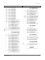
Specifications
Samsung Electronics 3-1
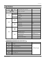
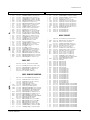
3. Specifications
Specifications are subject to change.
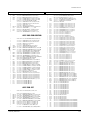
Television
System
Antena Input
CS
Power
Consumption
Requirements
Frequency
Sound
Output
Effect
Jacks
Front
(AV2)
Back
PAL/SECAM-B/G,D/K,L,I, NTSC-M
130W (Applied When 29” Flat)
220V Only
Free Voltage
50/60Hz
15W x 2CH
10W x 2CH
5W x 2CH
Virtual Dolby
Turbo Sound
Pseudo Stereo
RCA Input
S-VHS
Head-Phone
RCA99(AV2 Input/Out)
2Scart Input/Output
DVD Input(YPbPr)
AV2 Monitor Audio Output
S-VHS
75ohms, Coaxial Cable
Not Present R815
Option
Option
AV1 : Scart I/O, RGB Input,
RF Out
AV2 : Scart I/O, Monitor Out
Option
Option
Option
N
P
PF
PT
PW
MT
NT
WT
GW
Function
NICAM
2 TUNER PIP
2 TUNER PIP, NICAM, TTX
2 TUNER PIP, A2 STEREO, TTX
2 TUNER PIP, A2 STEREO
2 TUNER MULTI PIP, A2 STEREO,
NICAM, TTX
A2 STEREO, TTX
1 TUNER PIP, A2 STEREO, TTX
NOTE
“NICAM” means that
A2 STEREO + NICAM
Specifications for Model Name (Ex. CS29A6??8X/HAC)
29 Inch
21 Inch

3-2 Samsung Electronics
MEMO

Alignment and Adjustments
Samsung Electronics 4-1
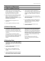
4. Alignment and Adjustments
4-1 General Alignment Instructions
1. Usually, a color TV-VCR needs only slight
touch-up adjustment upon installation. Check
the basic characteristics such as height,
horizontal and vertical sync and focus.
2. Observe the picture for good black and white
details. There should be objectionable color
shading; if color shading is present,
demagnetize, perform purity and convergence
adjustments described below.
3. Use the specified test equipment or its
equivalent.
4. Correct impedance matching is essential.
5. Avoid overload. Excessive signal from a
sweep generator might overload the front-end
of the TV. When inserting signal markers, do
not allow the marker generator to distort test
results.
6. Connect the TV only to an AC power source
with voltage and frequency as specified on the
backcover nameplate.
7. Do not attempt to connect or disconnect any
wires while the TV is turned on. Make sure
that the power cord is disconnected before
replacing any parts.
8. To protect against shock hazard, use an
isolation transformer.
4-2 Automatic Degaussing
A degaussing coil is mounted around the
picture tube, so that external degaussing after
moving the TV should be unnecessary. But
the receiver must be properly degaussed upon
installation.
The degaussing coil operates for about 1
second after the power is switched ON. If the
set is moved or turned in a different direction,
the power should be OFF for at least 10
minutes.
If the chassis or parts of the cabinet become
magnetized, poor color purity will result. If
this happens, use an external degaussing coil.
Slowly move the degaussing coil around the
faceplate of the picture tube and the sides and
front of the receiver. Slowly withdraw the coil
to a distance of about 6 feet before turning
power OFF.
If color shading persists, perform the
following Color purity and Convergence
adjustments.
4-3 High voltage Check
CAUTION : There is no high voltage adjustment
on this chassis. The B+ power supply should be
+135 volts (with full color- bar input and normal
picture level).
1. Connect a digital voltmeter to the second
anode of the picture tube.
2. Turn on the TV. Set the Brightness and
Contrast controls to minimum (zero beam
current).
3. Adjust the Brightness and contrast controls to
both extremes. Ensure that the high voltage
does not exceed 32 KV under any conditions.

Alignment and Adjustments
4-2 Samsung Electronics
4-5 SCREEN Adjustment
1. Input Toshiba Pattern
2. Enter “Service Mode”.(Refer to “Service Mode”)
3. Select “G2-Adjust”.
4. Set the values as example(Refer to page4-24).
4-4 Dynamic Focus Adjustment
1. A dynamic focus adjustment should be done
after replacing the CRT PCB, FBT or CRT.
2. Input a crosshatch pattern.
3. Enter “ STANDARD “ in video mode.
4. Turn the Dynamic focus VR fully clockwise
(maximum).( )
5. Turn the Static focus VR fully
counterclockwise (maximum).( )
6. Slowly turn the static focus VR
counterclockwise. Adjust until the
vertical line in the middle of the screen
has maximum clarity.( )
7. Slowly turn the dynamic focus VR (clockwise)
and adjust the 3rd horizontal line for
maximum clarity.( )
8. Repeat 4-7, if necessary.
STATIC FOCUS VR
DYNAMIC FOCUS VR
H
V
SCREEN
<FBT FOCUS PACK>
❷
❶
❷
❶
❷
❶
❷
❶
ex) IBRM = 220
WDRV = 35
CDL = 220
COLR G B = 150 150 150

Alignment and Adjustments
Samsung Electronics 4-3
When you do not have Toshiba Pattern, follow this method.
1. Set the TV on the condition that AV mode no signal(black)
2. Enter the “Menu” and set the mode to blue screen off.
3. Enter the “Service Mode”.
4. Select “ G2-Adjust”.
5. Set the values as example(Refer to page4-24).
ex) IBRM = 220
WDRV = 35
CDL = 220
COLR G B = 150 150 150
6. Turn the SCREEN VR until the value of “ MRCR G B” is about 120. Do not mind that
the “OSD” Color is red.
■ After completing G2-Adjust, follow this procedure.
① Enter the “Video Adjust 1”.
➁ Choose any item in menu. (ex. Select “Red Cutoff”)
➂ Change the value of item you select, and recover the value.
For example, when the value of “Red Cutoff” is 127, change the value to 128 and restore
the value to 127.
If you do not follow this procedure, the picture may be abnormal.
For example, when the TV set is on, the picture becames brighter gradually.
Note 1.
5. Turn the SCREEN VR until “MRCR G B” and “MRWDG” are green and those value are about 100.
(The incorrect SCREEN Voltage may result that “MRCR G B” and “MRWDG” should be red)

Alignment and Adjustments
4-4 Samsung Electronics
4-6 E
2
PROM (IC902) Replacement
1. When IC902 is replaced, all adjustment data revert to the initial values.
So, all adjustment values when servicing should be readjusted.
2. After IC902 is replaced, connect the AC power supply cord.
3. Turn the power switch ON.
4. In stand-by, warm up the TV for at least 10 seconds.
5. Power on the TV.
4-7 White Balance Adjustment
■ Equipment : Color-Analyzer (CA-100)
■ Input Signal : Pattern signal (Toshiba pattern)
1. Select STANDARD from the menu.
2. Input an 100% White pattern.
3. Enter the “Service Mode”. (Refer to “4-8 Service Mode”)
4. Warm up the TV set at least for 30 minutes.
5. Input a Toshiba pattern signal.
6. Enter the “Video Adjust1”.
- Adjust “Sub Contrast” so that Y (luminance) becomes 40 ft ± 3.
- Use “Red Drive” and “ Blue Drive” to adjust High-Light (x : 290, y : 300)
- Adjust “Sub Bright” so that Y (luminance) becomes 1.3ft ± 0.3.
- Use “Red Cutoff” and “Blue Cutoff” to adjust Low-Light (x : 290, y : 300).
7. Adjust CA-100 so that the final adjustment value can be fixed.
8. Use the Channel Up/Down (▲/▼) buttons to move the cursor on the adjustment modes.
9. Use the Volume +/- buttons to change the adjustment value.
■ SMPS Controller differentiol List
LOC.
DZ808
C811
C828
1265RD
1265RB
SPEC
MTZ8.28
47NF
221.50V
SPEC
MTZ8.28
47NF
221.50V
LOC.
DZ808
C811
C828

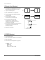
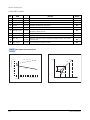
■ Background : It is occurred to service confusion
■ Cause : CRT Socket PCB change as CRT changing from Double Focus to Single Focus
■ How to service
Code : It is different to CRT Socket Code per focus type
Case :
1. Using CRT Socket PCB for Single Focus at CRT for Double Focus
(1) Change the CRT Socket in PCB(Single → Double).
(2) Cut the red-colored focus wire of FBT in set.
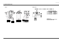
(3) Connect the wires at Focus terminal like picture #1 for short circuit using red-colored focos
wire of FTB.
2. Using CRT Socket PCB for Double Focus at CRT for Single Focus
(1) Change the CRT Socket in PCB(Double → Single).
(2) Cut the red-colored focus wire of FBT in set like picture #2.
❈ You mus tape the isolation parts for safety.
Alignment and Adjustments
Samsung Electronics 4-5
KS3A 29” Flat 50Hz, CRT Change(Double Focus
→→
Single Focu)
Note 2.
CRT Socket
For Double Focus
For Single Focus
Code No
3704-001032
3704-000114

Alignment and Adjustments
4-6 Samsung Electronics
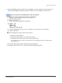
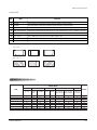
4-8 Factory Adjustment
1. To enter the “Service Mode”, Press the remote-control keys in this sequence :
- If you do not have Factory remote-control
- If you have Factory remote-control
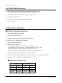
2. After the Service Mode is entered, the initial screen is as shown in the figure below.
*
Service
Deflection
Video Adjust 1
Video Adjust 2
Video Adjust 3
Option(81h 0Ch)
Reset
G2-Adjust
Others
3. Use the Channel Up/Down buttons to move the cursor in the adjustment parameters.
- When CRT, CRT PCB, FBT, E
2
PROM (sometimes MICOM) is replaced, the adjustment values
should be controlled.
- After the Service adjustment is completed, Do not select “Reset” in the service mode menu.
(After above procedure is done, power is on initially and the “Plug and Play” will be operated.)
PICTURE OFF PICTURE ON
DISPLAY
()
MENU
MUTE
PICTURE ON
DISPLAY
()
FACTORY
4-8-1 Service Mode
*
These hexa digits are check sum value which
depends on the MICOM.
If check sum value is changed, the value of
E
2
PROM Data newly initialed.
Note 3.

Alignment and Adjustments
Samsung Electronics 4-7
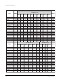
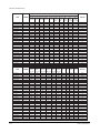
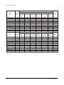
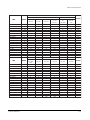
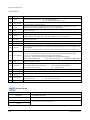
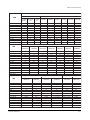
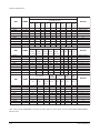
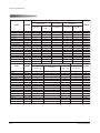
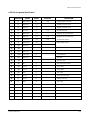
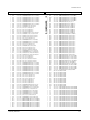
4-8-2 Memory Data
4-8-2(A) DEFLECTION (GEOMETRIC ADJUSTMENT VALUE)
No.
1
2
3
4
5
6
7
8
9
10
11
12
13
14
15
16
17
18
19
20
21
22
23
24
25
26
27
OSD
V Amp
V Shift
V Slope
V SC
H EW
H Trapizium
H Parabola
H Symmetry
H Corner
H Shift
Zoom 4:3 Para
4:3~16:9 Para
Wide-4:3 Para
Wide-Zoom Para
Wide-Zoom2 Para
Zoom1 Amp
Zoom2 Amp
TTX Position
D-TTX Posi
RGB Shift
PIP Contrast
PIP Tint
PIP V.Move(VSPDEL)
PIP PAL V.Pos
PIP NTSC V.Pos
PIP H.Pos
PIP BLKLG
Function
Adjusts Vertical picture size. Adjust 4:4 upper and below picture size in
lion head pattern at factory.
Adjusts Vertical picture position
Adjusts Vertical Slope Correction
Adjusts Vertical s-correction
Horizontal east west width. Adjust 5:5 left and right picture size in lion
head pattern at factory.
Adjusts horizontal Trapezium.
Adjusts Horizontal Parabola.
Adjusts Picture upper and below horizontal Symmetry.
Adjusts Picture upper and below Horizontal Corner.After adjust the
Parabola, adjust H corner vertical Line upper and below has nonlinear.
Adjusts Horizontal Position.
Corrects the vertical linearity in Zoom mode of P-SIZE.
The data depends on CRT (see data above)
Corrects the vertical linearity in 16:9 mode of P-SIZE.
The data differs according to CRT (see data above).
Corrects the vertical linearity in wide mode of P-SIZE.
The data differs according to CRT (see data above).
Corrects the vertical linearity in wide mode of P-SIZE.
The data differs according to CRT (see data above).
Corrects the vertical linearity in wide mode of P-SIZE.
The data differs according to CRT (see data above).
Adjusts vertical amplitude in zoom1
Adjusts vertical amplitude in zoom2. Zoom2 mode is a manual zoom
mode
Sets TTX Position.
Double -TTX position.
Adjusts RGB input signal Horizontal position
Adjusts PIP contrast.
Adjusts PIP Tint. It is a function to control color phase of NTSC signal in
PIP
PIP vertical sync pulse delay. When changing data, PIP jitters at two
points.
In this case, the PIP VSPDEL is set to the center between two points.
Adjusts Vertical position of PIP in PAL system.
Adjusts Vertical position of PIP in NTSC system.
Adjusts Horizontal Position of the PIP.
PIP blanking level green(PIP low light white balance).
It is used to control low light white balance in PIP
Remark
Adjust
Adjust
Adjust
Fix
Adjust
Adjust
Adjust
Fix
Adjust
Adjust
Fix
Adjust
Adjust
Adjust
Fix
Fix
Fix
Fix
Fix
Fix
Fix
Fix
Fix
Fix
Fix
Fix
Fix
Page is loading ...
Page is loading ...
Page is loading ...
Page is loading ...
Page is loading ...
Page is loading ...
Page is loading ...
Page is loading ...
Page is loading ...
Page is loading ...
Page is loading ...
Page is loading ...
Page is loading ...
Page is loading ...
Page is loading ...
Page is loading ...
Page is loading ...
Page is loading ...
Page is loading ...
Page is loading ...
Page is loading ...
Page is loading ...
Page is loading ...
Page is loading ...
Page is loading ...
Page is loading ...
Page is loading ...
Page is loading ...
Page is loading ...
Page is loading ...
Page is loading ...
Page is loading ...
Page is loading ...
Page is loading ...
Page is loading ...
Page is loading ...
Page is loading ...
Page is loading ...
Page is loading ...
Page is loading ...
Page is loading ...
Page is loading ...
Page is loading ...
Page is loading ...
Page is loading ...
Page is loading ...
Page is loading ...
Page is loading ...
Page is loading ...
Page is loading ...
Page is loading ...
Page is loading ...
Page is loading ...
Page is loading ...
Page is loading ...
Page is loading ...
Page is loading ...
Page is loading ...
Page is loading ...
Page is loading ...
Page is loading ...
Page is loading ...
Page is loading ...
Page is loading ...
Page is loading ...
Page is loading ...
Page is loading ...
Page is loading ...
Page is loading ...
Page is loading ...
-
 1
1
-
 2
2
-
 3
3
-
 4
4
-
 5
5
-
 6
6
-
 7
7
-
 8
8
-
 9
9
-
 10
10
-
 11
11
-
 12
12
-
 13
13
-
 14
14
-
 15
15
-
 16
16
-
 17
17
-
 18
18
-
 19
19
-
 20
20
-
 21
21
-
 22
22
-
 23
23
-
 24
24
-
 25
25
-
 26
26
-
 27
27
-
 28
28
-
 29
29
-
 30
30
-
 31
31
-
 32
32
-
 33
33
-
 34
34
-
 35
35
-
 36
36
-
 37
37
-
 38
38
-
 39
39
-
 40
40
-
 41
41
-
 42
42
-
 43
43
-
 44
44
-
 45
45
-
 46
46
-
 47
47
-
 48
48
-
 49
49
-
 50
50
-
 51
51
-
 52
52
-
 53
53
-
 54
54
-
 55
55
-
 56
56
-
 57
57
-
 58
58
-
 59
59
-
 60
60
-
 61
61
-
 62
62
-
 63
63
-
 64
64
-
 65
65
-
 66
66
-
 67
67
-
 68
68
-
 69
69
-
 70
70
-
 71
71
-
 72
72
-
 73
73
-
 74
74
-
 75
75
-
 76
76
-
 77
77
-
 78
78
-
 79
79
-
 80
80
-
 81
81
-
 82
82
-
 83
83
-
 84
84
-
 85
85
-
 86
86
-
 87
87
-
 88
88
-
 89
89
-
 90
90


Samsung WS28V55VS8XXEC User manual
- Category
- CRT TVs
- Type
- User manual
- This manual is also suitable for
Ask a question and I''ll find the answer in the document
Finding information in a document is now easier with AI
Related papers
-
Samsung CS21A530FLKXSV User manual
-
Samsung TXJ1996 User manual
-
TEAC CTW2850 User manual
-
-
-
-
-
-
-
Other documents
-
akira CT-21TF9CPSKD User manual
-
Daewoo DG-R520 User manual
-
 Wells-Gardner D9300 Series User manual
-
 Wells-Gardner D9100 User manual
-
Durabrand CB130DR8 User manual
-
 Pacific Digital PTV3606 User manual
-
Sylvania EWC20D4 User manual
-
-
-


