Page is loading ...

1521
Handheld Thermometer Readout
User’ s Guide
Rev. 571203 ENG
Hart Scientific

Limited Warranty & Limitation of Liability
Each product from Fluke's Hart Scientific Division ("Hart") is warranted to be free from defects in mate
-
rial and workmanship under normal use and service. The warranty period is one year for the Handheld
Thermometer Readout. The warranty period begins on the date of the shipment. Parts, product repairs,
and services are warranted for 90 days. The warranty extends only to the original buyer or end-user cus
-
tomer of a Hart authorized reseller, and does not apply to fuses, disposable batteries or to any other prod
-
uct which, in Hart's opinion, has been misused, altered, neglected, or damaged by accident or abnormal
conditions of operation or handling. Hart warrants that software will operate substantially in accordance
with its functional specifications for 90 days and that it has been properly recorded on non-defective me
-
dia. Hart does not warrant that software will be error free or operate without interruption. Hart does not
warrant calibrations on Handheld Thermometer Readouts.
Hart authorized resellers shall extend this warranty on new and unused products to end-user customers
only but have no authority to extend a greater or different warranty on behalf of Hart. Warranty support is
available if product is purchased through a Hart authorized sales outlet or Buyer has paid the applicable
international price. Hart reserves the right to invoice Buyer for importation costs of repairs/replacement
parts when product purchased in one country is submitted for repair in another country.
Hart's warranty obligation is limited, at Hart's option, to refund of the purchase price, free of charge re
-
pair, or replacement of a defective product which is returned to a Hart authorized service center within
the warranty period.
To obtain warranty service, contact your nearest Hart authorized service center or send the product, with
a description of the difficulty, postage, and insurance prepaid (FOB Destination), to the nearest Hart au-
thorized service center. Hart assumes no risk for damage in transit. Following warranty repair, the prod-
uct will be returned to Buyer, transportation prepaid (FOB Destination). If Hart determines that the
failure was caused by misuse, alteration, accident or abnormal condition or operation or handling, Hart
will provide an estimate or repair costs and obtain authorization before commencing the work. Following
repair, the product will be returned to the Buyer transportation prepaid and the Buyer will be billed for
the repair and return transportation charges (FOB Shipping Point).
THIS WARRANTY IS BUYER'S SOLE AND EXCULSIVE REMEDY AND IS IN LIEU OF ALL
OTHER WARRANTIES, EXPRESS OR IMPLIED, INCLUDING BUT NOT LIMITED TO ANY IM
-
PLIED WARRANTY OF MERCHANTABLILTY OR FITNESS FOR A PARTICULAR PURPOSE.
HART SHALL NOT BE LIABLE FOR ANY SPECIAL, INDIRECT, INCIDENTAL. OR CONSE
-
QUENTIAL DAMAGES OR LOSSES, INCLUDING LOSS OF DATA, WHETHER ARISING FROM
BREACH OF WARRANTY OR BASED ON CONTRACT, TORT, RELIANCE OR ANY OTHER
THEORY.
Since some countries or states do not allow limitation of the term of an implied warranty, or exclusion or
limitation of incidental or consequential damages, the limitations and exclusions of this warranty may not
apply to every buyer. If any provision of this Warranty is held invalid or unenforceable by a court of com
-
petent jurisdiction, such holding will not affect the validity or enforceability of any other provision.
Rev. 571203
Fluke Corporation, Hart Scientific Division
799 E. Utah Valley Drive American Fork, UT 84003-9775 USA
Phone: +1.801.763.1600 Telefax: +1.801.763.1010
E-mail: [email protected]
www.hartscientific.com
Subject to change without notice. Copyright © 2005 Printed in USA

Table of Contents
1 Before You Start . . . . . . . . . . . . . . . . . . . . . . . . . . 1
1.1 Symbols Used . . . . . . . . . . . . . . . . . . . . . . . . . . . . 1
1.2 Safety Information . . . . . . . . . . . . . . . . . . . . . . . . . . 2
1.2.1 Warnings . . . . . . . . . . . . . . . . . . . . . . . . . . . . . . . . . . . . . 2
1.2.2 Cautions . . . . . . . . . . . . . . . . . . . . . . . . . . . . . . . . . . . . . 3
1.3 Authorized Service Centers. . . . . . . . . . . . . . . . . . . . . . 4
2 Introduction . . . . . . . . . . . . . . . . . . . . . . . . . . . . 7
3 Specifications and Environmental Conditions . . . . . . . . . . 9
3.1 Specifications . . . . . . . . . . . . . . . . . . . . . . . . . . . . . 9
3.2 Environmental Conditions. . . . . . . . . . . . . . . . . . . . . . 10
4 Quick Start . . . . . . . . . . . . . . . . . . . . . . . . . . . . 11
4.1 Unpacking . . . . . . . . . . . . . . . . . . . . . . . . . . . . . . 11
4.2 Use Proper Care with the 1521 and Accessories . . . . . . . . . . 11
4.3 Learn About the Features and Components . . . . . . . . . . . . . 11
4.4 Connect the Probe . . . . . . . . . . . . . . . . . . . . . . . . . . 11
4.5 Connect the Power Source . . . . . . . . . . . . . . . . . . . . . 12
4.6 Switch the Power On . . . . . . . . . . . . . . . . . . . . . . . . 12
4.7 Measure Temperature . . . . . . . . . . . . . . . . . . . . . . . . 12
5 Parts and Controls . . . . . . . . . . . . . . . . . . . . . . . . 13
5.1 Front Features . . . . . . . . . . . . . . . . . . . . . . . . . . . . 13
5.2 Top and Side Features . . . . . . . . . . . . . . . . . . . . . . . . 15
5.3 Back Features . . . . . . . . . . . . . . . . . . . . . . . . . . . . 16
5.4 Internal Features. . . . . . . . . . . . . . . . . . . . . . . . . . . 16
5.5 Accessories . . . . . . . . . . . . . . . . . . . . . . . . . . . . . 17
6 General Operation . . . . . . . . . . . . . . . . . . . . . . . . 19
6.1 Battery. . . . . . . . . . . . . . . . . . . . . . . . . . . . . . . . 19
6.2 DC Power Source . . . . . . . . . . . . . . . . . . . . . . . . . . 20
6.3 Power Button . . . . . . . . . . . . . . . . . . . . . . . . . . . . 21
6.4 Display and Backlight . . . . . . . . . . . . . . . . . . . . . . . . 21
6.5 Probe . . . . . . . . . . . . . . . . . . . . . . . . . . . . . . . . 22
i

6.6 INFO-CON Connector . . . . . . . . . . . . . . . . . . . . . . . 23
7 Display Functions. . . . . . . . . . . . . . . . . . . . . . . . . 25
7.1 Blank Mode . . . . . . . . . . . . . . . . . . . . . . . . . . . . . 26
7.2 Min/Max Mode . . . . . . . . . . . . . . . . . . . . . . . . . . . 27
7.3 Hold Mode . . . . . . . . . . . . . . . . . . . . . . . . . . . . . 27
7.4 Delta(x) Mode . . . . . . . . . . . . . . . . . . . . . . . . . . . . 27
7.5 Units . . . . . . . . . . . . . . . . . . . . . . . . . . . . . . . . . 28
7.6 Rate . . . . . . . . . . . . . . . . . . . . . . . . . . . . . . . . . 28
7.7 Resolution . . . . . . . . . . . . . . . . . . . . . . . . . . . . . . 28
7.8 CAL MODE . . . . . . . . . . . . . . . . . . . . . . . . . . . . . 29
7.8.1 Mtr Due . . . . . . . . . . . . . . . . . . . . . . . . . . . . . . . . . . . . . 30
7.8.2 Prb Due . . . . . . . . . . . . . . . . . . . . . . . . . . . . . . . . . . . . . 30
7.8.3 Time . . . . . . . . . . . . . . . . . . . . . . . . . . . . . . . . . . . . . . . 30
7.8.4 Passcode. . . . . . . . . . . . . . . . . . . . . . . . . . . . . . . . . . . . . 30
7.8.5 Date . . . . . . . . . . . . . . . . . . . . . . . . . . . . . . . . . . . . . . . 31
7.8.6 Probe Lock . . . . . . . . . . . . . . . . . . . . . . . . . . . . . . . . . . . 31
7.8.7 Prb #. . . . . . . . . . . . . . . . . . . . . . . . . . . . . . . . . . . . . . . 31
7.8.8 Prb Type . . . . . . . . . . . . . . . . . . . . . . . . . . . . . . . . . . . . . 31
7.8.9 ITS-90 . . . . . . . . . . . . . . . . . . . . . . . . . . . . . . . . . . . . . . 32
7.8.10 IEC751 . . . . . . . . . . . . . . . . . . . . . . . . . . . . . . . . . . . . . 33
7.8.11 CVD . . . . . . . . . . . . . . . . . . . . . . . . . . . . . . . . . . . . . . . 33
7.8.12 YSI-400 . . . . . . . . . . . . . . . . . . . . . . . . . . . . . . . . . . . . . 34
7.8.13 THERM . . . . . . . . . . . . . . . . . . . . . . . . . . . . . . . . . . . . 34
7.8.14 Probe Wires . . . . . . . . . . . . . . . . . . . . . . . . . . . . . . . . . . . 35
7.8.15 PCal . . . . . . . . . . . . . . . . . . . . . . . . . . . . . . . . . . . . . . . 35
7.8.16 PDue . . . . . . . . . . . . . . . . . . . . . . . . . . . . . . . . . . . . . . 35
7.8.17 Filter. . . . . . . . . . . . . . . . . . . . . . . . . . . . . . . . . . . . . . . 36
7.8.18 MCal . . . . . . . . . . . . . . . . . . . . . . . . . . . . . . . . . . . . . . 36
7.8.19 MDue . . . . . . . . . . . . . . . . . . . . . . . . . . . . . . . . . . . . . . 36
7.8.20 CAL1 and CAL2 . . . . . . . . . . . . . . . . . . . . . . . . . . . . . . . . 36
8 Communications Interface. . . . . . . . . . . . . . . . . . . . 37
8.1 RS-232 Connection . . . . . . . . . . . . . . . . . . . . . . . . . 37
8.2 Communication Command List . . . . . . . . . . . . . . . . . . . 38
8.2.1 Primary Commands . . . . . . . . . . . . . . . . . . . . . . . . . . . . . . . 38
8.2.2 Calibration Commands . . . . . . . . . . . . . . . . . . . . . . . . . . . . . 39
9 Calibration . . . . . . . . . . . . . . . . . . . . . . . . . . . . 43
9.1 Required Equipment. . . . . . . . . . . . . . . . . . . . . . . . . 43
9.2 Calibration Procedure . . . . . . . . . . . . . . . . . . . . . . . . 43
10 Maintenance . . . . . . . . . . . . . . . . . . . . . . . . . . . 45
ii

11 Troubleshooting. . . . . . . . . . . . . . . . . . . . . . . . . . 47
11.1 An Error Message Is Displayed . . . . . . . . . . . . . . . . . . . 47
11.2 CE Comments . . . . . . . . . . . . . . . . . . . . . . . . . . . . 48
11.2.1 EMC Directive . . . . . . . . . . . . . . . . . . . . . . . . . . . . . . . . . 48
11.2.1.1 Immunity Testing . . . . . . . . . . . . . . . . . . . . . . . . . . . . . . . . . . . . 49
11.2.1.2 Emission Testing . . . . . . . . . . . . . . . . . . . . . . . . . . . . . . . . . . . . 49
11.2.2 Low Voltage Directive (Safety) . . . . . . . . . . . . . . . . . . . . . . . . . 49
iii

iv
Figures and Tables
Table 1 International Electrical Symbols . . . . . . . . . . . . . . . . . . . . . 1
Figure 1 Front of the 1521 . . . . . . . . . . . . . . . . . . . . . . . . . . . . . 13
Figure 2 Top and Side View . . . . . . . . . . . . . . . . . . . . . . . . . . . . 15
Figure 3 INFO-CON Connector . . . . . . . . . . . . . . . . . . . . . . . . . . 17
Figure 4 Battery Installation . . . . . . . . . . . . . . . . . . . . . . . . . . . . 19
Figure 5 12V DC Power Source Polarity . . . . . . . . . . . . . . . . . . . . . 21
Figure 6 Probe Wiring Diagrams . . . . . . . . . . . . . . . . . . . . . . . . . 24
Figure 7 Operating Modes Flowchart . . . . . . . . . . . . . . . . . . . . . . . 26
Figure 8 RS-232 Wiring . . . . . . . . . . . . . . . . . . . . . . . . . . . . . . 37

1 Before You Start
1.1 Symbols Used
Table 1 lists the International Electrical Symbols. Some or all of these symbols
may be used on the instrument or in this manual.
Symbol Description
AC (Alternating Current)
AC-DC
Battery
CE Complies with European Union Directives
DC
Double Insulated
Electric Shock
Fuse
PE Ground
Hot Surface (Burn Hazard)
Read the User’s Manual (Important Information)
Off
On
1
1 Before You Start
Symbols Used
Table 1 International Electrical Symbols

Symbol Description
Canadian Standards Association
OVERVOLTAGE (Installation) CATEGORY II, Pollution Degree 2 per IEC1010-1 re
-
fers to the level of Impulse Withstand Voltage protection provided. Equipment of
OVERVOLTAGE CATEGORY II is energy-consuming equipment to be supplied from
the fixed installation. Examples include household, office, and laboratory appliances.
C-TIC Australian EMC Mark
The European Waste Electrical and Electronic Equipment (WEEE) Directive
(2002/96/EC) mark.
1.2 Safety Information
Use this instrument only as specified in this manual. Otherwise, the protection
provided by the instrument may be impaired.
The following definitions apply to the terms “Warning” and “Caution”.
• “Warning” identifies conditions and actions that may pose hazards to the
user.
• “Caution” identifies conditions and actions that may damage the instru-
ment being used.
1.2.1
Warnings
To avoid personal injury, follow these guidelines.
•
DO NOT use this unit in environments other than those listed in the
User’s Guide.
•
Follow all safety guidelines listed in the User’s Guide.
•
Calibration equipment should only be used by trained personnel.
•
If this equipment is used in a manner not specified by the manufacturer,
the protection provided by the equipment may be impaired.
•
Before initial use, or after transport, or after storage in humid or semi-hu
-
mid environments, or anytime the instrument has not been energized for
more than 10 days, the instrument needs to be energized for a "dry-out"
period of 2 hours before it can be assumed to meet all of the safety re
-
quirements of the IEC 1010-1. If the product is wet or has been in a wet
environment, take necessary measures to remove moisture prior to apply
-
ing power such as storage in a low humidity temperature chamber
operating at 50°C for 4 hours or more.
•
This instrument can measure extreme temperatures. Precautions must be
taken to prevent personal injury or damage to objects. Probes may be ex
-
tremely hot or cold. Cautiously handle probes to prevent personal injury.
1521 Handheld Thermometer Readout
User’s Guide
2

Carefully place probes on a heat/cold resistant surface or rack until they
reach room temperature.
•
The AC adapter can present safety concerns if misused or damaged. To
avoid the risk of electric shock or fire, do not use the AC adapter outdoors
or in a dusty, dirty, or wet environment. If the cord, case, or plug of the
adapter is damaged in any way, discontinue its use immediately and have
it replaced. Never disassemble the AC adapter. Use only the AC adapter
provided with the instrument or equivalent adapter recommended by the
manufacturer of this instrument.
•
The AC adapter has circuits with high voltage inside that could present
danger of electrical shock or fire if exposed. If the AC adapter is damaged
in any way or becomes hot, discontinue its use immediately, disconnect it
from any AC supply, and have it replaced. Do not attempt to open, repair,
or continue using a damaged or defective AC adapter.
•
The instrument batteries can present danger if not handled properly. To
avoid the risk of exposure to dangerous substances or explosion, immedi
-
ately remove the batteries and discontinue use if they leak or become
damaged. Never allow the batteries to be shorted, heated, punctured, or
dropped. If the instrument is physically damaged, immediately remove
the batteries to insure that they do not become shorted. While removed
from the instrument, store the batteries in a location so that they do not
come into contact with metal or fluids that might short circuit the batteries
and where they are safe from excessive temperatures. Used batteries must
be disposed of properly. Check your local regulations for additional infor-
mation. You may return the used batteries to the manufacturer. Never dis-
pose of batteries in fire which may result in explosion with the possibility
of personal injury or property damage.
• DO NOT use this instrument in combination with any probe (RTD or
thermistor) to measure the temperature or resistance of any device that is
electrically energized. Severe electric shock, personal injury, or death may
occur.
1.2.2
Cautions
To avoid possible damage to the instrument, follow these guidelines.
•
If the instrument is dropped, struck, or handled in a way that causes inter
-
nal or external physical damage, immediately unplug the AC adapter, re
-
move the batteries, discontinue use, and contact the factory for repair. Do
not attempt to disassemble or repair the instrument, batteries, or AC
adapter. Refer repairs or replacement components to the manufacturer.
•
The instrument and thermometer probes are sensitive and can be easily
damaged. Always handle these devices with care. DO NOT allow them to
be dropped, struck, stressed, or overheated.
•
DO NOT leave the AC adapter plugged in for more than 24 consecutive
hours or the battery life could be degraded.
3
1 Before You Start
Safety Information

•
Probes are fragile devices which can be damaged by mechanical shock,
overheating, and absorption of moisture or fluids in the wires or hub.
Damage may not be visibly apparent but nevertheless can cause drift, in
-
stability, and loss of accuracy. Observe the following precautions:
•
DO NOT allow probes to be dropped, struck, bent, or stressed.
•
DO NOT overheat probes beyond their recommended temperature range.
•
DO NOT allow any part of the probe other than the sheath to be im
-
mersed in fluid.
•
DO NOT allow the probe hub or wires to be exposed to excessive temper
-
atures.
•
Keep the probe wires clean and away from fluids.
1.3 Authorized Service Centers
Please contact one of the following authorized Service Centers to coordinate
service on your Hart product:
Fluke Corporaton, Hart Scientific Division
799 E. Utah Valley Drive
American Fork, UT 84003-9775
USA
Phone: +1.801.763.1600
Telefax: +1.801.763.1010
E-mail: [email protected]
Fluke Nederland B.V.
Customer Support Services
Science Park Eindhoven 5108
5692 EC Son
NETHERLANDS
Phone: +31-402-675300
Telefax: +31-402-675321
E-mail: [email protected]
Fluke Int'l Corporation
Service Center - Instrimpex
Room 2301 Sciteck Tower
22 Jianguomenwai Dajie
1521 Handheld Thermometer Readout
User’s Guide
4

Chao Yang District
Beijing 100004, PRC
CHINA
Phone: +86-10-6-512-3436
Telefax: +86-10-6-512-3437
E-mail: [email protected]
Fluke South East Asia Pte Ltd.
Fluke ASEAN Regional Office
Service Center
60 Alexandra Terrace #03-16
The Comtech (Lobby D)
118502
SINGAPORE
Phone: +65 6799-5588
Telefax: +65 6799-5588
E-mail: [email protected]
When contacting these Service Centers for support, please have the following
information available:
• Model Number
•
Serial Number
•
Voltage
•
Complete description of the problem
5
1 Before You Start
Authorized Service Centers

2 Introduction
The 1521 Handheld Thermometer Readout is a low-cost, high-accuracy digital
thermometer readout designed to be used with PRTs and thermistors. The
unique combination of features makes this instrument suitable for a wide vari
-
ety of applications in industry. Features and capabilities of the 1521 include the
following:
•
Measures with platinum resistance thermometers (PRTs) and thermistors
•
Works with Hart’s special INFO-CON probe connector (which is partially
based on U.S. Patent 5,857,777) to automatically recognize the type of
sensor and its characteristics
•
Automatically alerts the operator when the probe calibration or meter cal
-
ibration expires
•
Measures with an accuracy of ±0.025°C at 25°C with PRTs and ±0.005°C
at 25°C with thermistors
• Accepts three- or four-wire sensors to eliminate lead resistance errors
• Is immune to thermoelectric EMF
• Measures with a fast one-second measurement cycle
• Displays maximum, minimum, and delta temperatures
• Stores up to six measurements in memory
• Uses a unique factory-assigned pass-code to protect programmed settings
• Displays measurements and settings on a high-contrast LCD display
• Communicates with other equipment using an RS-232 serial interface
•
Can be powered from its AC adapter or rechargeable battery
7
2 Introduction

3 Specifications and Environmental
Conditions
3.1 Specifications
Resistance Range
0
Ω
to 500 k
Ω
Resistance Accuracy, PRT, one
year
†
0
Ω
to 25
Ω
: 0.002
Ω
25
Ω
to 400
Ω
: 0.008% (80 ppm) of reading
Resistance Accuracy, thermistor,
one year
†
0
Ω
to2k
Ω
:0.4
Ω
2k
Ω
to 200 k
Ω
: 0.02% (200 ppm) of reading
200 k
Ω
to 500 k
Ω
: 0.03% (300 ppm) of reading
Temperature Range PRT: –200°C to 962°C (–328°F to 1764°F)
Thermistor: –50°C to 150°C (–58°F to 302°F)
Temperature Accuracy, PRT
†
–200°C to 100°C: ±0.025°C (0.045°F)
100°C to 400°C: ±0.05°C (0.09°F)
400°C to 800°C: ±0.1°C (0.18°F)
800°C to 962°C: ±0.15°C (0.27°F)
Temperature Accuracy,
2.25 k
Ω
thermistor
†
–50 to 25°C: ±0.005°C (0.009°F)
25°C to 50°C: ±0.01°C (0.018°F)
50°C to 75°C: ±0.03°C (0.054°F)
75°C to 100°C: ±0.08°C (0.144°F)
Temperature Accuracy,
10 k
Ω
thermistor
†
0 to 50°C: ±0.005°C (0.009°F)
50°C to 75°C: ±0.01°C (0.018°F)
75°C to 100°C: ±0.02°C (0.036°F)
100°C to 125°C: ±0.05°C (0.09°F)
125°C to 150°C: ±0.1°C (0.18°F)
Temperature Accuracy,
100 k
Ω
thermistor
†
0 to 50°C: 0.006°C (0.011°F)
50°C to 150°C: 0.009°C (0.016°F)
Resistance Resolution
0.001
Ω
Temperature Resolution 0.001°C, F, K, R
Probe IEC-751 or DIN-43760 PRT
Callendar-Van Dusen calibrated PRT; nominal 100
Ω
ITS-90 calibrated 25
Ω
or 100
Ω
PRT
YSI-400 series or equivalent 2252
Ω
thermistor
Steinhart-Hart thermistor polynomial; nominal R(25°C) 2k
Ω
to
100k
Ω
Probe Connector Hart Scientific INFO-CON connector
Maximum Acceptable Probe Lead
Resistance
10
Ω
Probe Excitation Current PRT: 0.5 mA
Thermistor: 5
μ
A
Measurement Period 1 second
9
3 Specifications and Environmental Conditions
Specifications

Digital Filter Exponential with adjustable time constant (1 to 60 seconds)
Remote Communications RS-232 serial
Display LCD, 6-digit x 7-segment with 16-character alphanumeric
Operating Temperature Range 0 to 40°C (32 to 104°F) absolute
15 to 35°C (59 to 95°F) full accuracy
Power 12 VDC (AC adapter included)
Rechargeable NiMH batteries (included)
Safety OVERVOLTAGE (Installation) CATEGORY II, Pollution Degree 2 per
IEC1010-1 refers to the level of Impulse Withstand Voltage protec
-
tion provided. Equipment of OVERVOLTAGE CATEGORY II is en
-
ergy-consuming equipment to be supplied from the fixed installation.
Examples include household, office, and laboratory appliances.
Size 7.75"H x4.2"Wx1.5"D (20 cm H x 11 cm W x 4 cm D)
Weight 0.4 kg (1.0 lb.)
†
Accuracy specifications apply from 15 to 35°C. Accuracy specifications over the entire absolute operating
range are 1.5 times the stated values. Temperature accuracy does not include probe uncertainty or probe
characterization errors. The practical measurement range may be limited by the sensor.
3.2 Environmental Conditions
Although the instrument has been designed for optimum durability and trou-
ble-free operation, it must be handled with care. The instrument should not be
operated in an excessively dusty, dirty, or wet environment. Maintenance and
cleaning recommendations can be found in the Maintenance section of this
manual.
For full accuracy, operate the instrument in ambient temperatures between
15-35°C (59-95°F). Do not operate the instrument in an environment colder
than 5°C (41°F) or warmer than 50°C (122°F).
The instrument operates safely under the following conditions:
•
Operating temperature range: absolute 5–50°C (41–122°F);
full accuracy15-35°C (59-95°F)
•
ambient relative humidity: maximum 80% for temperature <31°C, de
-
creasing linearly to 50% at 40°C
•
Pressure: 75kPa-106kPa
•
Vibration should be minimized
•
Altitude less than 2,000 meters
•
Indoor use only
1521 Handheld Thermometer Readout
User’s Guide
10

4 Quick Start
This section briefly explains the basics of setting up and operating your 1521
Thermometer.
4.1 Unpacking
Carefully unpack the 1521 and accessories and inspect them to make sure all
components are present and in satisfactory condition. Verify that the following
items are present:
•
1521 Thermometer
•
AC Adapter (clamp-on ferrite installed)
•
Serial Cable
•
User’s Guide
• Report of Calibration
• Calibration Label
• Pass-code Notice
• INFO-CON Connector
• Clamp-on ferrite with instructions for probe
• Probe (optional—must be purchased separately)
If all items are not present, call an Authorized Service Center (see Section 1.3).
4.2 Use Proper Care with the 1521 and Accessories
First and most important is to understand the safety issues related to the 1521
and its accessories. Be aware that potential hazards exist due to high tempera
-
tures, high voltages, and battery chemicals. Carefully read Section .
CAUTION: The 1521 and any thermometer probes are sensitive instru
-
ments that can be easily damaged. Always handle these devices with care.
DO NOT allow them to be dropped, struck, stressed, or overheated.
4.3 Learn About the Features and Components
Familiarize yourself with the features and accessories of the 1521 by reading
Section 5.
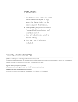
4.4 Connect the Probe
The PRT or thermistor probe connects to the top of the 1521 using Hart’s
unique INFO-CON probe connector. The probe connector is inserted into the
11
4 Quick Start
Unpacking

top of the instrument with the ridged side down. It will fit snugly and lock into
place when it is fully inserted.
The INFO-CON probe connector includes a memory device that stores the
unique characteristics of the probe, allowing the 1521 to measure tempera
-
ture accurately. If your probe was purchased from Hart for use with the 1521 it
should already have the connector attached and properly programmed. You can
use your own probe with the 1521, but you must attach it with an INFO-CON
connector. See Section 6.6 for more information on the INFO-CON connector.
4.5 Connect the Power Source
The 1521 draws power from either a DC power supply (the included AC
adapter) connected to the DC input or the internal rechargeable battery pack. To
use the AC adapter, plug it into a wall outlet of the appropriate voltage and in
-
sert the DC plug into the DC power input of the 1521 (see Figure 2.) To use the
battery pack it must first be fully charged using the AC adapter (see Section
6.1).
4.6 Switch the Power On
Power is switched on and off with the power button located below and to the
left of the display. To switch the power on, hold the power button down for at
least two seconds. (To switch power off, momentarily press the power button
again.) The instrument takes a few seconds to power up, initialize itself, and be-
gin normal operation. During initialization the lower line of the display shows
the manufacturer, model number, firmware version, and the state of battery
charge or the message “External power” if the AC adapter is attached. The
1521 reads important information about the attached probe from the
INFO-CON connector that it subsequently uses to calculate temperature.
The 1521 then performs a memory check of critical parameters, such as the cal
-
ibration parameters CAL1 and CAL2. During this check the lower line of the
display reads “Checking Memory”. If a “Memory Error” or “Memory Recover”
message is displayed, see Section 12.1, Troubleshooting, for additional infor
-
mation and instructions.
4.7 Measure Temperature
After initialization the upper line of the display will begin to show temperature
measurements sensed at the tip of the probe. Place the tip of the probe into the
object that you want to measure the temperature. DO NOT force the probe or
otherwise allow it to be bent, stressed, or overheated. It can be easily damaged
if misused. For further suggestions on handling the probe and using the 1521
and probe to measure temperature accurately, see Section 6.5. For information
on the various modes of operation of the 1521see Section 7.
1521 Handheld Thermometer Readout
User’s Guide
12

5 Parts and Controls
The functions of the various features of the 1521 are described below.
5.1 Front Features
The front of the 1521 features the LCD display and control buttons.
13
5 Parts and Controls
Front Features

Display-The display shows the current temperature (or resistance) measure
-
ment on the large numeric upper portion of the display. It can also show a vari
-
ety of information on the smaller alphanumeric lower portion such as
minimum, maximum, hold temperatures, delta(x), and other instrument
settings.
Power and Backlight button-This button turns the instrument on or off. If the
power is on, pressing the button for three seconds toggles the backlight on or
off (see Section 6.3). Note: using the backlight drains the battery more
quickly.
ENT (enter) button-This button is pressed to accept changes to a setting and,
in some modes, to store the most recent measurement.
CLR (clear) button-This button cancels changes to a setting and in the
MIN/MAX mode resets the minimum and maximum to the last measurement.
UpandDownbuttons-These buttons are used to change values and settings.
MODE button-This button advances through operating modes and program
-
ming functions (see Section 7).
1521 Handheld Thermometer Readout
User’s Guide
14

5.2 Top and Side Features
The top and side of the 1521 feature the probe connector, DC power input, se
-
rial port, and infrared window.
Probe Connector - At the top of the thermometer is the opening where the
probe connector is inserted. The probe must be connected using an INFO-CON
probe connector to measure temperature (see Section 6.6).
DC Power Input-The AC adapter plugs into the DC power input to recharge
the battery and to power the instrument while the battery is being charged (see
Section 6.2).
Serial Port-The RS-232 serial port provides a means of connecting the 1521 to
a computer or a printer using the included serial cable (see Section 8). The
baud rate is fixed at 2400 baud, the linefeed is fixed to ON (all carriage returns
are followed by a linefeed (ASCII decimal 10), and the duplex is fixed to Half
disabling the echo.
Infrared Window-The infrared window has no functionality.
15
5 Parts and Controls
Top and Side Features
DC Power Input
Stand
Probe Connector
Top View
Side View
Serial Port
Infrared Window
(not used)
Figure 2 Top and Side View

5.3 Back Features
See Figure 4 on page 19.
Stand-The stand at the back of the 1521 can be flipped down to prop up the in
-
strument for better viewing.
Battery Compartment- Behind the stand is the compartment that contains the
battery pack. The battery pack can be accessed if necessary by opening the bat
-
tery cover with a small Philips screwdriver (see Section 6.1).
Serial Number Label-Also behind the stand is the serial number label that
uniquely identifies the instrument.
5.4 Internal Features
The significant components inside the 1521 are described here.
Battery-The 1521 has an internal rechargeable battery pack that can be re
-
charged by the AC adapter without removing the battery. It can be used and re-
charged many times. If necessary, it can be easily removed and replaced (see
Section 6.1).
Micro-controller-The 1521 uses a micro-controller to control all its functions.
The micro-controller manages the measurement process, retrieves measurement
data from the analog-to-digital converter (ADC), places measurements and
other information on the display, senses button actions, reads battery status in-
formation from the power control circuit, and handles communications through
the serial port.
Power Control Circuit-The power control circuit manages the electrical power
that drives all the circuits. It handles switching between the two sources of
power (DC input and battery pack), regulates voltages, monitors the state of
battery charge, and manages battery charging.
Analog-to-Digital Converter and Measurement Circuit-The ADC takes an
analog signal produced by the probe and converts it to a digital value that can
be read by the micro-controller. The ADC used in the 1521 was selected for its
excellent resolution, linearity, and stability. The measurement circuit built
around the ADC was carefully designed for accuracy and stability to match the
ADC. The measurement circuit allows complete rejection of probe wire resis
-
tance effects that would otherwise seriously limit accuracy. Offsets from
sources such as thermoelectric EMF are also completely rejected. This is done
using a current reversal technique with the probe current alternating at a rate of
one cycle per second. Self-heating is minimized by using low sensing currents.
For PRTs the current is only 0.5 mA. For thermistors the current is only 0.005
mA.
1521 Handheld Thermometer Readout
User’s Guide
16
/