
1 69-0564—3
D.F. • Rev. 11-94 • • ©Honeywell Inc. 1994 • Form Number 69-0564—3
T8195B/Q682B,C, Y8224A
Heating or Cooling and Heating/Cooling
New Construction Thermostat,
Wallplate and Subbase
Installation Instructions for the Trained Service Technician.
Preparation
Check thermostat and subbase (if used) suitability for the
heating, cooling, or heating/cooling system. Refer to Table 1.
Assemble tools required: flat bladed screwdriver, hand or
power drill with 3/16-in. drill bit, wire cutter/stripper or
sharp knife, bubble level or plumb bob and line.
Assure power is off to the heating, cooling, or heating/
cooling system at the main fuse panel. Most buildings have
a separate switch box or circuit breaker for disconnecting
power to the heating and cooling (if applicable) equipment.
This thermostat is compatible with most heating, cooling,
or heating/cooling systems. Refer to Table 1 for thermostat
and system compatibility information.
a
If thermostat is not compatible with the system being controlled, the system will not operate. No hazard exists. The thermo-
stat will not be damaged unless it is used to directly control a line voltage system. For proper system operation, a Honeywell
R841 or R8239D1015 Isolating Relay must be added to the thermostat control circuit.
b
Consult manufacturer for installation requirements.
M3375
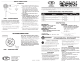
Recycling Notice
This control contains mercury in a sealed tube. Do not
place control in the trash at the end of its useful life.
If this control is replacing a control that contains mercury
in a sealed tube, do not place your old control in the trash.
Contact your local waste management authority for in-
structions regarding recycling and the proper disposal of this
control, or of an old control containing mercury in a sealed
tube.
If you have questions, call Honeywell Inc. at 1-800-
468-1502.
TABLE 1—THERMOSTAT AND SYSTEM COMPATIBILITY.
Type of Heating System
to be Controlled Conditions/Compatibility
Electric (Line Voltage)—typical
baseboard and radiant
• The R8239D1015 Isolating Relay or R841 Silent Switching Center must be
installed in the thermostat control circuit.
a
Fan Coil Unit • Compatible. Assure correct subbase identity is selected for fan control.
Gas—Direct Spark Ignition
(DSI), Intermittent Pilot (IP), and
Standing Pilot (SP)
• Compatible. Assure that 24V control transformer common is accessible for
connection to thermostat cable conductor and power to the transformer is not
regularly interrupted by high temperature or limit operation.
Heat Pump • Compatible. Assure correct subbase identity is selected for fan control and
changeover control (O terminal for cool and B terminal for heat). Jumper Y
to W for heat pump compressor control.
Hot Water Zone • Honeywell 2-wire valves are compatible.
• Some non-Honeywell 2-wire valves require an R8239D1015 Isolating Relay
in the thermostat control circuit.
a
• Some 3-wire valves require an R8239A1052 Isolating Relay in the
thermostat control circuit.
a, b
Oil • Assure that the 24V control transformer common is accessible for connection
to thermostat cable conductor and power to the transformer is not regularly
interrupted by high temperature, purge cycle, or limit operation.
Vent Damper • Honeywell damper motors are compatible.
• Some non-Honeywell damper motors require an R8239D1015 Isolating
Relay in the thermostat control circuit.
a
Check control amperage
requirement.
Warm Air Zone • Most are compatible.
M3375

69-0564—3 2
Installation
WHEN INSTALLING THIS PRODUCT…
1. Read these instructions carefully. Failure to follow
them could cause a hazardous condition.
2. Installer must be a trained experienced service technician.
3. After installation is complete, check out product op-
eration as provided in these instructions.
IMPORTANT: An incorrectly leveled subbase will cause
the temperature control to deviate from setpoint. It is
not a calibration problem.
CAUTION
1. Disconnect power supply to prevent electrical
shock or equipment damage.
2. To prevent interference with the thermostat link-
age, keep wire length to a minimum and run
wires as close as possible to the subbase.
3. Do not overtighten thermostat captive mount-
ing screws because damage to subbase threads
can result.
4. Do not short across coil terminals on relay. This
can burn out the thermostat heat anticipator.
LOCATION
Locate thermostat about 5 ft [1.5m] above the floor in an
area with good air circulation at average temperature.
Do not mount the thermostat where it may be affected by:
— drafts, or dead spots behind doors and in corners.
— hot or cold air from ducts.
— radiant heat from the sun or appliances.
— concealed pipes and chimneys.
— unheated (uncooled) areas such as an outside wall
behind the thermostat.
Run wires from the heating, cooling, or heating/cooling
equipment to the new thermostat location.
IMPORTANT: This control requires an additional con-
ductor to the control transformer common (e.g., a
typical 2-wire heating system requires three wires be
pulled, a 4-wire heating/cooling requires five wires).
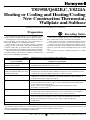
UNPACK THERMOSTAT
Handle your new thermostat carefully; rough handling
may interfere with its accuracy. Before unpacking, refer to
Fig. 1.
Remove and discard the shipping wrap.
IMPORTANT: Save package of screws and instructions
for the homeowner.
Remove the thermostat cover by lifting from the bottom.
Set aside cover until needed later.
Carefully remove the material protecting the mercury
switch bulb.
Loosen two captive mounting screws, and separate wall-
plate (if provided) from back of thermostat base.
MOUNT WALLPLATE OR SUBBASE
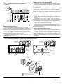
Wall Mounting (Fig. 2)
Hold the wallplate or subbase in position on wall (Fig. 2).
Mark holes on the wall for anchors. Use spirit level to
make sure the wallplate or subbase is level.
Fig. 1—Unpack thermostat.
CAPTIVE MOUNTING
SCREWS
THERMOSTAT BASE
12
1
1
10
9
8
7
6
5
4
3
2
1
12
11
1
0
9
8
7
6
M8605
REMOVE
PACKING
MATERIAL
LIFT
COVER
THERMOSTAT
COVER
Drill 3/16-in. holes, and gently tap anchors into holes
until flush with the wall.
Pull wires through the large wiring hole in the wallplate or
subbase.
Loosely fasten the wallplate or subbase to the wall with
the three screws. Do not completely tighten the screws.
Carefully level the wallplate or subbase (Fig. 3), and
firmly tighten the screws.
Fig. 2—Mounting wallplate or subbase to wall.
3 SCREW HOLES
WITH PLASTIC
ANCHORS
HEATING-ONLY
WALLPLATE
M857
M1552A
AUTO OFF
COOL
HEATON
FAN
R
G
O
W
Y
B
3 SCREW HOLES
WITH PLASTIC
ANCHORS
HEATING/COOLING SUBBASE

3 69-0564—3
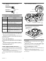
Fig. 3—Leveling methods for wallplate or
subbase.
AUTO OFF
COOL
HEATON
FAN
B
O
W
Y
R
G
M1555
SPIRIT LEVEL
PLUMB
LINE
PLUMB
BOB OR
WEIGHT
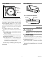
Outlet Box Mounting (Fig. 4)
Use a horizontally mounted outlet box if possible. If a
vertical outlet box is used, mount the wallplate or subbase on
a 202689A Cover Plate Assembly (ordered separately). Fol-
low the instructions provided with the cover plate assembly.
Align the wallplate or subbase mounting holes on the
outlet box and loosely fasten with two screws.
Carefully level the wallplate or subbase (Fig. 3), and
firmly tighten the screws.
WIRE WALLPLATE OR SUBBASE
Follow the instructions provided by the heating, cooling
or heating/cooling equipment manufacturer. If not available,
refer to the Typical Wiring Diagrams section at the end of
this publication.
Disconnect the power supply before making wiring con-
nections to prevent electrical shock or equipment damage.
NOTE: All wiring must comply with local electrical codes
and ordinances.
Wallplate (Heating or Cooling Systems)
Refer to Fig. 5 and strip the thermostat wire insulation as
necessary.
For heating-only systems, connect wires to R, W, and C
terminals. For cooling-only systems, connect wires R, Y,
and C terminals. Firmly tighten the screws. The system low-
voltage transformer powers the timer (Fig. 11).
Push excess wire back into the wall.
Plug the hole in the wall with nonhardening caulk, putty,
or nonflammable insulation to prevent drafts from affecting
thermostat operation.
Subbase (Heating/Cooling Systems)
Refer to Fig. 5, and strip the thermostat wire insulation as
necessary.
Connect the wires to the corresponding terminals on the
subbase. If labels do not agree with your new subbase, refer
to Table 2 and the installation instructions furnished with
the subbase.
Fig. 4—Mounting wallplate or subbase on horizontal outlet box.
M1553A
EXISTING
HORIZONTAL
OUTLET BOX
HEATING/
COOLING
SUBBASE
AUTO OFF
COOL
HEATON
FAN
R
G
O
W
Y
B
EXISTING
HORIZONTAL
OUTLET BOX
WALLPLATE
R
W
M856
M1554A
B
O
W
Y
R
G
VERTICAL
OUTLET
BOX
ADAPTER
RING
1
2
NOT INCLUDED WITH UNIT.
ACCESSORY PARTS AVAILABLE.
SUBBASE OR
WALLPLATE
1
2
2
COVER
PLATE
MOUNTING
SCREWS (2)

69-0564—3 4
Fig. 5—Methods of connecting terminals.
BARRIER
FOR WRAPAROUND
CONNECTION—
STRIP 7/16 in. [11 mm]
FOR STRAIGHT
CONNECTION—
STRIP 5/16 in. [8 mm]
M1556B
TABLE 2—TERMINAL DESIGNATIONS.
Subbase
Terminal
Control
Function
R Control transformer power.
W Heating control circuit.
Y Cooling control circuit; jumper to W
for heat pump compressor control if
no P terminal on subbase.
G Fan control circuit.
C Clock control (transformer common).
O Cooling damper or changeover/
reversing valve, makes continuously
in cool.
B Heating damper or changeover/
reversing valve, makes continuously
in heat.
The timer is powered by the system low-voltage trans-
former. 24 Vac must be maintained across terminals R and C.
Push excess wire back into the wall.
Plug the hole in wall with nonhardening caulk, putty, or
nonflammable insulation to prevent drafts from affecting
thermostat operation.
MOUNT THE THERMOSTAT
Note the tabs on the top inside edge of the thermostat base.
These tabs fit the slots molded into the top of the wallplate or
subbase.
Hang the thermostat base on the wallplate or subbase.
Insert the two captive mounting screws located in the
bottom corners of the base (Fig. 6).
Firmly tighten the screws.
INSERT TIMER BATTERIES (OPTIONAL)
Power is supplied to the clock by the 24-Vac transformer.
Two AAA alkaline backup batteries (not included) may be
installed to supply power to the timer if power is interrupted
due to power failure.
Install the batteries in the thermostat (Fig. 7).
Once a year or when batteries are dead, replace with two
new AAA alkaline batteries. We recommend Energizer
®
batteries.
Fig. 6—Thermostat mounting.
TAB (2)
MOUNTING SLOT (2)
CAPTIVE
MOUNTING SCREWS
THERMOSTAT
BASE
WALLPLATE
OR SUBBASE
12
11
10
9
8
7
6
5
4
3
2
1
12
1
1
10
9
8
7
6
M8603
Fig. 7—Insert timer backup batteries.
BATTERY LOCATION FOR
(2) AAA BATTERIES;
INSTALL WITH POSITIVE
ENDS UP
M8585
SET TIMER
Adjust the clock by moving the knob clockwise . Do
not reverse the knob.
When time is correctly set, the time indicator arrow
(triangle shape) points to the corresponding daytime (light)
or nighttime (dark) portion of the program dial.
ATTACH THERMOSTAT COVER
Make sure the packing inserts in the thermostat base are
removed.
Place the two tabs on the upper edge of the cover into the
mounting slots in the thermostat base (Fig. 9).
Swing the cover downward until it catches at the bot-
tom of the base.

5 69-0564—3
Fig. 8—Set timer.
TIMER
SETTING
KNOB
TIME
INDICATOR
ARROW
M5161
PROGRAM
PINS (4)
SEE OWNER'S
MANUAL FOR
DETAILS
SET TEMPERATURE CONTROL LEVERS
The two levers on the top of the thermostat control the
low and high temperatures for energy savings and comfort
control (Fig. 10). The lever on the left (blue mark) controls
the lower temperature. The lever on the right (red mark)
controls the higher temperature.
We recommend pushing the levers together at an appro-
priate temperature for either heat or cool until the occupant
programs the thermostat and makes the final temperature
selections.
SET SUBBASE SWITCHES (IF APPLICABLE)
The subbase system switch controls system operation as
follows:
HEAT: Heating system is controlled by the thermostat.
Cooling system is off.
COOL: Cooling system is controlled by the thermostat.
Heating system is off.
OFF: Both the heating and cooling systems are off. If the
fan switch is in the AUTO position, the fan is also off.
The subbase fan switch controls fan operation as follows:
ON: Fan operates continuously.
AUTO: Fan operates with the cooling equipment as con-
trolled by the thermostat or with the heating equipment
as controlled by the plenum switch. In electric heat,
heat pump, and fan coil systems, the fan is controlled
by the thermostat in heating and cooling.
To switch positions, use thumb or index finger to slide
lever to the desired position. For proper circuit operation,
switch lever must stop in detent over the desired function
indicator mark.
Fig. 9—Attach cover.
50
60
70
80
M8604
Fig. 10—Temperature control levers.
50
60
70
80
HIGH TEMPERATURE
(RED MARK)
SET LEVER
LOW TEMPERATURE
(BLUE MARK)
SET LEVER
M859
Checkout
CAUTION
Do not check operation by shorting across termi-
nals of system controls. This will damage the heat
anticipator.
HEATING-ONLY SYSTEM
Turn on power to the furnace.
Push both temperature setting levers together at least 5° F
[3° C] above the room temperature. The main burner should
come on. The fan will start when the furnace heats up.
Move both levers 5° F [3° C] below the room tempera-
ture. The burner should shut off.
Operate the entire heating system at least one complete
cycle.
If thermostat fails any test, refer to the Troubleshooting
Guide in the Owner’s Manual.
Reset both the temperature setting levers to the desired
temperatures.

69-0564—3 6
COOLING-ONLY SYSTEM
Turn on power to the cooling equipment.
Push both temperature setting levers together at least 5° F
[3° C] below the room temperature. The cooling equipment
will operate, and the fan will start. Allow for any time delay
that may be built into the compressor control circuit.
NOTE: To avoid compressor damage, do not operate the
system when outdoor temperature is below 50° F [10° C].
Refer to manufacturer recommendations.
Move both levers 5° F [3° C] above room temperature.
The cooling equipment and the fan should shut off.
Operate the entire cooling system at least one complete
cycle.
If thermostat fails any test, refer to the Troubleshooting
Guide in the Owner’s Manual.
Reset both the temperature setting levers to the desired
temperatures.
HEATING/COOLING SYSTEM
Turn on power to the furnace and cooling system.
Place the system switch lever to HEAT and fan switch
lever to AUTO.
Push both temperature setting levers together at least 5° F
[3° C] above room temperature. The main burner should
come on. The fan will start when the furnace heats up. (If
central electric heat, fan coil or heat pump system, fan starts
immediately.)
Move both levers 5° F [3° C] below room temperature.
The burner should shut off.
Place the system switch lever to COOL and the fan switch
lever to AUTO. The cooling equipment will operate, and the
fan will start. Allow for any time delay that may be built into
the compressor control circuit.
NOTE: To avoid compressor damage, do not operate the
system when outdoor temperature is below 50° F [10° C].
Refer to manufacturer recommendations.
Move both temperature setting levers together at least
5° F [3° C] above the room temperature. The cooling equip-
ment should shut off.
Place the fan switch to ON. The fan should run continu-
ously with the system switch in any position.
Place the system switch to OFF. Move both temperature
setting levers to various positions. The heating and cooling
systems should not operate.
Operate the entire system for at least one complete cycle
with the system switch at COOL and one complete cycle
with the switch at HEAT.
If thermostat fails any test, refer to the Troubleshooting
Guide in the Owner’s Manual.
Reset both the temperature setting levers to the desired
temperatures.
Leave Owner’s Manual and Assistance Information in a
convenient place for the building occupant or provide with
other appliance manuals.
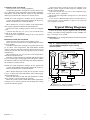
Typical Wiring Diagrams
Follow the hookup diagram supplied with your heating,
cooling, or heating/cooling equipment. If not available, use
Figs. 11 through 13 as a guide.
REMEMBER: Your wiring must follow local electrical codes
and ordinances.
Fig. 11—Typical hookup for T8195B Thermo-
stat and Q682C Wallplate in gas heating
control system.
H
C
THERMOSTAT
WALLPLATE
M503A
POWER SUPPLY. PROVIDE DISCONNECT MEANS AND
OVERLOAD PROTECTION AS REQUIRED.
1
HEAT
ANTICIPATOR
HEAT
ANTICIPATOR
COOL
ANTICIPATOR
W
Y
R
GAS
CONTROL
1
L2
L1
(HOT)
TIMER
C
FALL
FALL
H
C

7 69-0564—3
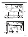
Fig. 12—Typical hookup for T8195B Thermostat and Q682B Subbase in conventional heating/
cooling system.
HEAT
OFF
COOL
ON
AUTO
H
C
FAN
SWITCH
THERMOSTAT
SUBBASE
M8606
POWER SUPPLY. PROVIDE DISCONNECT MEANS AND OVERLOAD PROTECTION AS REQUIRED.
REMOTE INDICATION FOR FILTER OPTIONAL.
1
SYSTEM
SWITCH
HEAT
OFF
COOL
G
Y
B
W
FAN
RELAY
COOLING
RELAY
HEATING
DAMPER
HEAT
RELAY
COOLING
DAMPER
1
L2
L1
(HOT)
TIMER
C
2
2
FALL
H
C
HEAT/COOL
ANTICIPATOR
FALL
O
X
FILTER
LED
SWITCH
R
HEAT
OFF
COOL
ON
AUTO
H
C
FAN
SWITCH
THERMOSTAT
SUBBASE
M573B
POWER SUPPLY. PROVIDE DISCONNECT MEANS AND OVERLOAD PROTECTION AS REQUIRED.1
COOL
ANTICIPATORS
HEAT
ANTICIPATORS
SYSTEM
SWITCH
HEAT
OFF
COOL
G
Y
W
R
FAN
RELAY
HEAT
RELAY
COMPRESSOR
CONTACTOR
1
L2
L1
(HOT)
TIMER
C
FALL
FALL
H
C

Automation and Control Solutions
Honeywell International Inc. Honeywell Limited—Honeywell Limitée
1985 Douglas Drive North 35 Dynamic Drive
Golden Valley, MN 55422 Scarborough, Ontario M1V 4Z9
-
 1
1
-
 2
2
-
 3
3
-
 4
4
-
 5
5
-
 6
6
-
 7
7
-
 8
8


Honeywell T8195B User manual
- Category
- Household fans
- Type
- User manual
Ask a question and I''ll find the answer in the document
Finding information in a document is now easier with AI
Related papers
-
Honeywell T8190A User manual
-
Honeywell Q682A User manual
-
Honeywell T8095A User manual
-
-
-
-
-
-
-
Other documents
-
Pelican RT1 Installation guide
-
Robertshaw RS8110 User manual
-
Lux Products T10-1141 Owner's manual
-
-
-
-
 Hunter Fan 43320 Owner's manual
-
 Hunter Fan 43302 Owner's manual
-
White Rodgers Type 1E56 User manual
-

