
Document: GF07Z301 Rev. 1
INSTRUCTION MANUAL
INSTALLATION - OPERATION - MAINTENANCE
HV6AS Vacuum Circuit Breakers – Fixed Type
4.8 & 7.2kV Voltage Classes
APPLICABLE MODEL NUMBERS:
(Manual Operation Types)
HV6AS-U
HV6AS-L
(Motor Operation Types)
HV6AS-MU
HV6AS-ML
Issued: 2/2000
Supercedes First Issue Dated 2/99.


INSTRUCTION MANUAL
For the Installation, Operation and Maintenance of
HV6AS Vacuum Circuit Breakers – Fixed Type
4.8 & 7.2kV Voltage Classes
Never attempt to install, operate, maintain or dispose of this equipment until
you have first read and understood all of the relevent product warnings and
user directions that are contained in this Instruction Manual.
To contact Toshiba, address all correspondence to:
Field Service Department
Toshiba International Corporation
13131 West Little York Road
Houston, Texas 77041 USA
or call:
(713) 466-0277
(800) 231-1412
(800) 527-1204 (Canada)
Fax: (713) 466-8773
Please complete the following information for your records and retain with this manual:
Model: ___________________________________
Serial Number:_____________________________
Date of Installation: _________________________
Inspected by: ______________________________
Reference Number: _________________________
© TOSHIBA INTERNATIONAL CORPORATION, 2000
WARNING


SAFETY Page 1
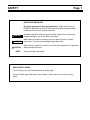
IMPORTANT MESSAGES
Read this manual and follow its instructions. Signal words such as
DANGER, WARNING and CAUTION will be followed by important safety
information that must be carefully reviewed.
Indicates a situation which will result in death, serious injury, and severe
property damage if you do not follow instructions.
Means that you might be seriously injured or killed if you do not follow
instructions. Severe property damage might also occur.
Means that you might be injured if you do not follow instructions. Equipment
damage might also occur.
NOTE Gives you helpful information
READ SAFETY SIGNS
To avoid injury, you must read and follow all safety signs.
Keep the safety signs visible and in good shape. Never remove or cover any safety
signs.
DANGER
WARNING
CAUTION

Page 2 SAFETY
QUALIFIED OPERATORS ONLY
Only qualified persons are to install, operate, or service this equipment according to all
applicable codes and established safety practices.
A qualified person must:
1) Carefully read the entire instruction manual.
2) Be skilled in the installation, construction or operation of the equipment and
aware of the hazards involved.
3) Be trained and authorized to safely energize, deenergize, clear, ground,
lockout and tag circuits in accordance with established safety practices.
4) Be trained and authorized to perform the service, maintenance or repair of
this equipment.
5) Be trained in the proper care and use of protective equipment such as rubber
gloves, hard hat, safety glasses, face shield, flash clothing, etc. in
accordance with established practices.
6) Be trained in rendering first aid.
SAFETY CODES
Toshiba HV6AS vacuum circuit breakers are designed and built in accordance with JIS
C 4603-1990 and JEC-2300-1985. Installations must comply with all applicable state
and local codes, adhere to all applicable National Electric Code (NFPA 70) standards
and instructions provided in this manual.

SAFETY Page 3
HAZARDOUS VOLTAGE will cause severe injury, death, fire, explosion and
property damage.
• Turn off and lock out Primary and Control Circuit Power before servicing.
• Keep all panels and covers securely in place.
• Never Defeat, Modify, or Bypass any Safety Interlocks
• Qualified Operators only
SAFETY....................................................................................................................................................1
DANGER

Page 4 TABLE OF CONTENTS
INTRODUCTION ......................................................................................................................................6
GENERAL DESCRIPTION.......................................................................................................................7
Components..................................................................................................................................7
Indicators and Controls .................................................................................................................8
RECEIVING, INSPECTION AND HANDLING..........................................................................................9
Receiving and Unpacking .............................................................................................................9
Acceptance Inspection..................................................................................................................9
Handling and Moving ..................................................................................................................10
INSTALLATION......................................................................................................................................11
Rating Verification.......................................................................................................................11
Mounting the Circuit Breaker to a Panel .....................................................................................12
Mounting Directly to a Shelf ........................................................................................................14
Main Circuit Cable Connections..................................................................................................15
Ground Connections ...................................................................................................................16
Control Circuit Connections ........................................................................................................17
Additional Auxiliary Switch ..........................................................................................................17
PRE-ENERGIZATION CHECK ..............................................................................................................18
General .......................................................................................................................................18
Electrical Checks ........................................................................................................................18
OPERATION...........................................................................................................................................19
Manual Operation........................................................................................................................19
Electrical Operation.....................................................................................................................19
Undervoltage Trip........................................................................................................................24
MAINTENANCE .....................................................................................................................................25
Maintenance Program.................................................................................................................25
Maintenance Record...................................................................................................................25
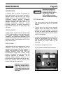
Servicing Equipment ...................................................................................................................25
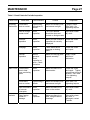
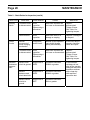
Inspection and Maintenance Types ............................................................................................26
Table 1. Tightening Torques ......................................................................................................26
Table 2. Check Points for Periodic Inspection ...........................................................................27
Vacuum Check............................................................................................................................29
DISPOSAL..............................................................................................................................................31
STORAGE ..............................................................................................................................................32
Storage........................................................................................................................................32

TABLE OF CONTENTS Page 5
Inspection During Storage...........................................................................................................32
SPECIFICATIONS..................................................................................................................................33
Table 3. Ratings – Manual Operation HV6AS-U and HV6AS-L Types ......................................33
Table 4. Ratings – Motor Operation HV6AS-MU and HV6AS-MU Types ..................................33
WARRANTY AND LIMITATION OF LIABILITY.....................................................................................34

Page 6 INTRODUCTION
It is the intent of this manual to provide a guide for safely installing, operating and maintaining Toshiba
vacuum circuit breakers. This manual consists of a section of general safety instructions and is marked
throughout with warning symbols. Read this manual thoroughly before installation, operation and
maintenance of this equipment.
This manual and all accompanying drawings should be considered a permanent part of the equipment.
They should be readily available for review and reference at all times. This manual is not intended to
cover all details, combinations, or variations of the equipment. Always refer to drawings accompanying
the equipment for additional details.
All safety warnings must be followed to ensure personal safety. General safety instructions are
found on pages 1 through 3. Read and save these instructions for future reference.
Follow all precautions to attain proper equipment performance and longevity.
Dimensions shown in the manual are in metric and/or their English equivalent.
This manual is divided into major sections of interest, as follows:
GENERAL DESCRIPTION – Provides a description of the equipment, information on major
components and how they function, plus rating information.
RECEIVING, INSPECTION AND HANDLING – Describes procedures for receiving, unpacking,
inspecting, handling, lifting and moving the circuit breaker.
INSTALLATION – Provides information on installing the circuit breaker in the switchgear cell along with
breaker racking procedures.
PRE-ENERGIZATION CHECK – Provides a checklist for preparing the equipment for energization.
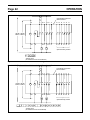
OPERATION – Provides information on manual and electrical operation of the circuit breaker, circuit
diagrams, operating sequence description and operation of circuit breaker optional accessories.
MAINTENANCE – Lists the basic maintenance procedures for this equipment necessary for safe and
reliable operation.
DISPOSAL – Lists procedures for the safe disposal of the equipment when the service life has expired.
STORAGE – Provides guidelines for storing new equipment for an extended period of time.
SPECIFICATIONS – Covers ratings and other specifications of the circuit breaker.
WARRANTY AND LIMITATION OF LIABILITY – Details Toshiba International Corporation’s standard
warranty terms.

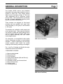
GENERAL DESCRIPTION Page 7
The Toshiba HV6AS vacuum circuit breakers
described in this manual are suitable for use on
systems of 4.8kV and 7.2kV voltage classes
which require interrupting ratings of 16kA and
14kA respectively and a continuous current
rating of 630A. The circuit breakers are intended
for use in limited applications requiring small
physical size and low maintenance.
These breakers are designed for fixed panel
mounting and are available with upper main
circuit terminals (U, MU types) or rear terminals
(L, ML types).
The breakers are available as both manual and
motor-operated types. Motor-operated breakers
use a motor to charge the closing springs and to
close the breaker upon command. Both types
can be tripped electrically and also include
undervoltage release.
Arc interruption is accomplished inside sealed
vacuum interrupters mounted on track-resistant
insulators. Vacuum interrupters use low-surge
contact materials which exhibit low current
chopping levels reducing switching overvoltages.
Fig. 1 and Fig. 2 illustrate and identify the major
components of the circuit breakers.
COMPONENTS LEGEND:
1) Manual closing handle
2) Manual trip lever
3) On-Off indicator
4) Spring charge indicator (MU and ML only)
5) Operations counter
6) Secondary control circuit terminal block
7) Main circuit terminals
8) Auxiliary switch
9) Grounding terminal
Fig. 1 U and MU Type Circuit Breaker (Upper
Main Circuit Terminals)
Fig. 2 L and ML Type Circuit Breaker (Rear
Main Circuit Terminals)

Page 8 GENERAL DESCRIPTION
SAFETY DEVICES
Safety interlocks and guards are provided as an
integral part of the equipment design. These
devices are provided for safety to the operator.
Never defeat, modify or
bypass any safety devices,
interlocks or operating
mechanism. This would
make the equipment
unsafe. Fire, explosion,
severe injury, death and
property damage could
occur.
Do not operate this
equipment unless all
covers and panels are in
place.
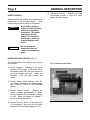
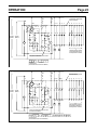
INDICATORS AND CONTROLS (Fig. 3)
The following front panel indicators and controls
are provided:
1) On-Off Indicator - Indicates if the circuit
breaker is OFF (Green) or ON (Red). When
the indicator reads OFF, the main contacts of
the circuit breaker are open. When the
indication is ON, the main contacts are
closed.
2) Closing Spring Status Indicator (MU, ML
types only) - Indicates if the closing springs
are CHARGED (Yellow) or DISCHARGED
(White).
3) Manual Closing Handle – Rotating the
handle clockwise approximately 75° closes
the circuit breaker (On-Off indicator changes
to ON). When the handle is released, it
returns to its normal position.
4) Manual Trip Lever (Red) – Pushing the lever
in the direction of the arrow trips the circuit
breaker (On-Off indicator changes to OFF).
5) Operations Counter - Indicates the total
accumulated number of times the circuit
breaker has been closed.
Fig. 3 Indicators and Controls
DANGER
WARNING

RECEIVING, INSPECTION AND HANDLING Page 9
RECEIVING AND UNPACKING
The circuit breaker units are subjected to factory
production testing prior to being packed and
shipped.
ACCEPTANCE INSPECTION
Confirm that the circuit breaker unit is complete,
correct as specified and undamaged from
shipment and handling.
Upon receipt of the equipment, do the following:
1) Make an immediate inspection for damage
which might have occurred during shipment.
If damage is discovered, it should be noted
with the carrier prior to accepting the
shipment, if possible.
2) Carefully unpack the equipment sufficiently to
check for missing parts or concealed
damage.
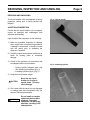
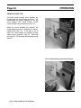
3) Check for the presence of accessories that
are shipped with the circuit breaker:
- Closing Handle (shipped loose with
MU and ML type breakers) (Fig. 4)
- Insulating cylinders (qty-6) (Fig. 5)
3) Keep the circuit breaker upright.
Never lay the circuit
breaker on its side or
upside down. This may
cause damage.
4) File a claim with the carrier for any damaged
or missing items and immediately notify the
nearest Toshiba representative.
Do not install or energize
equipment that has been
damaged. Damaged
equipment can fail during
operation, resulting in fire
and explosion.
Fig. 4 Closing Handle
Fig. 5 Insulating Cylinder
CAUTION
WARNING

Page 10 RECEIVING, INSPECTION AND HANDLING
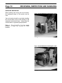
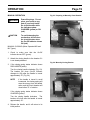
HANDLING AND MOVING
When handling and moving the circuit breaker,
the techniques shown in this section may be
used.
Care and caution should be used when handling
the circuit breaker units to avoid damage to the
equipment and personal injury. Always keep the
circuit breaker in a generally upright position.
Refer to Fig. 6 and Fig. 7 for the correct
methods of lifting and moving the circuit
breakers.
.
Fig. 6 Correct Method for Handling the U and
MU Type Circuit Breakers
Fig. 7 Correct Method for Handling the L and
ML Type Circuit Breakers

INSTALLATION Page 11
Do not install this
equipment in areas where
unusual service conditions
exist. Using this equipment
in other than usual service
conditions can result in
equipment failure.
Toshiba HV6AS circuit breakers are intended for
use in usual service conditions as defined in
IEEE C37.20.2. The temperature of the cooling
air (ambient air temperature) surrounding the
breaker should be between the limits of -5°C
(23°F) and +40°C (104°F). The altitude of the
equipment installation should not exceed 3300 ft
(1000 m).
In particular, avoid the following installation
conditions:
- Excessive dust
- Corrosive gases
- Extreme variations in temperature
- Very high or low humidity
- Vibrations
- Inclined locations
If there is a chance that condensation can occur
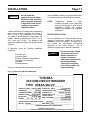
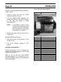
Fig. 8 Typical Circuit Breaker Nameplate
at the installation location, a space heater should
be installed inside the circuit breaker enclosure.
NOTE: Temperature, altitude or other
conditions outside of the usual limits
may require derating or other special
equipment. Contact your nearest
Toshiba representative for additional
information.
RATING VERIFICATION
Prior to Installation, the maximum fault current
capacity of the power system at the point of
installation should be verified. This value must
not exceed the symmetrical interrupting
capability of the circuit breaker. Fig. 8
illustrates a typical circuit breaker nameplate.
Do not exceed the ratings
specified on the circuit
breaker nameplate or
system accessories.
Underrated equipment can
fail during operation
causing fire, explosion,
severe injury, death, and
property damage.
WARNING
DANGER
HOUSTON, TEXAS U.S.A.
RATED VOLTAGE
FREQUENCY
IMPULSE LEVEL
DIELECTRIC
SER. No.
PARTS & WIRING, SEE INSTRUCTIONS
CONTINUOUS AMPS
WEIGHT
SHORT CKT. AMPS
INTERRUPTING TIME
VACUUM CIRCUIT BREAKER
UV TRIP VOLTS
MFG. STANDARD
SHUNT TRIP VOLTS
TOSHIBA INTERNATIONAL CORPORATION
CLOSE VOLTS
50/60 Hz
22 kV AC RMS
60 kV, CREST
630A, RMS
kg
MFG. DATE
lbs
HV6AS-
7.2/4.8 kV, RMS
TYPE
JIS C 4603-1990
JEC-2300-1985
120 VAC
VDC
VDC
14/16 kA, RMS
3 CYCLES
24 53
120 VAC / 125
125
GF07Z301
MU-VV
98700221 7/98
TOSHIBA

Page 12 INSTALLATION
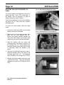
MOUNTING THE CIRCUIT BREAKER TO A
PANEL
The circuit breakers are designed to mount to a
panel made from 11 ga. (.12 in.) thick steel. If
the breaker must be mounted to a panel of
different thickness, contact Toshiba.
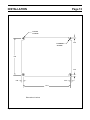
Panel cutout dimensions for the circuit breakers
are given in Fig. 12. One cutout size is used for
all breaker types.
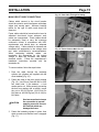
To mount the circuit breaker, follow the steps
below:
1. Loosen the small screw (M5) on the closing
handle and remove the handle.
2. Remove the four front plate mounting bolts
(M8) from the circuit breaker (Fig. 9).
Remove the spacer washers between the
front plate and breaker and discard them
(make sure none are left inside the breaker),
3. Align the breaker with the cutout and
mounting holes on the panel to which it is to
be mounted (Fig. 10). Some breakers are
furnished with two hooks which may be used
to temporarily attach the breaker to the
panel.
4. Using the four M8 bolts removed in step 2,
fasten the breaker and its front plate to the
mounting panel (Fig. 11). The tightening
torque should be 120-150 kgf-cm (9-11 ft-lb).
5. Replace the closing handle removed in step
1 and the M5 screw. The screw should be
tightened to a torque of 40-50 kgf-cm (35-43
in-lb).
Fig. 9 Remove Front Plate and Spacer
Washers
Fig. 10 Align Breaker With Panel Cutout
Fig. 11 Fasten Breaker and Front Plate to
Panel

INSTALLATION Page 13
Fig. 12 Panel Cutout Dimensions
10.71
0.38 RADIUS
4 PLACES
0.343 DIA
4 PLACES
0.25
0.25
0.25
0.25
8.03
Dimensions in Inches

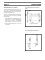
Page 14 INSTALLATION
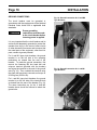
MOUNTING DIRECTLY TO A SHELF
The shelf should be flat and level within ± 0.5
mm (± 0.02 in.). If there are any noticeable gaps
between the breaker and the shelf, fill them in
using flat washers as spacers.
Check to make sure the breaker On-Off indicator
shows OFF (green), then mount it by following
the steps below:
1. Fasten the breaker onto steel angles or to a
flat plate (Fig. 13). Use M8 hex head bolts
(either 50 mm or 35 mm). The tightening
torque should be 120-150 kgf-cm (9-11 ft-lb).
2. Either mounting method shown in (Fig. 14)
may be used.
Fig. 13 Mounting Breaker to Flat Plate or
Angles
Fig. 14 Optional Hardware Orientation
ANGLE
PANEL
M8 x 35MM OR M8 x 50MM BOLT

INSTALLATION Page 15
MAIN CIRCUIT CABLE CONNECTIONS
Cables which connect to the circuit breaker
should be routed to avoid interference with sharp
edges and moving parts. Minimum bending
radius for the type of cable used should be
observed.
Power cables should be braced and/or laced to
withstand short-circuit forces wherever such
cables are unsupported. Power cables should
be adequately sized to carry the maximum
continuous current in accordance with NEC
requirements and should have an adequate
voltage rating. Cables should be dressed and
terminated as appropriate to the voltage class
and cable manufacturer’s recommendations.
When terminating shielded cables, use
termination kits appropriate for the system
voltage to taper the insulation and reduce
electrical stress. Follow the manufacturer’s
installation instructions provided with the
termination kit.
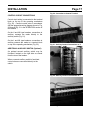
To connect cables, follow the steps below:
1. Pass the cable through the insulating
cylinder (six cylinders are supplied with the
circuit breaker) (Fig. 15).
2. Fasten the cable to the main circuit terminal
(Fig. 16). Use 35 mm Class 8.8 M10 or M12
hex head bolts, 2 flat washers, a lock
washer and a nut. While securely preventing
the bolt from rotating with a wrench, torque
the nut to 250-315 kgf-cm (18-23 ft-lb) for
M10 bolts or 450-565 kgf-cm (32-41 ft-lb) for
M12 bolts.
Use two wrenches to torque
the connection to prevent
applying excessive force to
the terminal which can
damage the frame.
3. Fasten the insulating cylinder in place, then
check to make sure that the hook is engaged
(Fig. 17).
Fig. 15 Pass Cable Through Insulating
Cylinder
Fig. 16 Fasten Cable to Main Circuit
Terminal
Fig. 17 Fasten Insulating Cylinder
CAUTION

Page 16 INSTALLATION
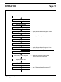
GROUND CONNECTIONS
The circuit breaker must be grounded in
accordance with the requirements of the National
Electrical Code, Article 250 or applicable local
standards.
Proper grounding
connections must be made
to the circuit breaker before
incoming power is applied.
It is very important that the circuit breaker and its
enclosure be adequately grounded to protect the
operator from injury in the event of short circuits
or other abnormal occurences and to ensure that
the metal parts of the equipment, other than live
parts, remain at ground potential.
For U and MU type circuit breakers, the ground
terminal is on the left side of the operating
mechanism as viewed from the rear of the
breaker. To make the ground connection, first
remove the fastening M6 hex head bolt and
crimp-on terminal (provided with the breaker)
and crimp the terminal to the end of the ground
wire (Fig. 18). Then, reattach the terminal using
the same bolt previously removed and torque to
50-65 kgf-cm (43-56 in-lb).
For L and ML type circuit breakers, the ground
terminal is on the left side of the terminal block
as viewed from the rear of the breaker (Fig. 19).
The same instructions as for the U and MU
breaker above should be followed to attach the
ground wire.
Fig. 18 Ground Connection for U and MU
Type Breakers
Fig. 19 Ground Connection for L and ML
Type Breakers
WARNING
Page is loading ...
Page is loading ...
Page is loading ...
Page is loading ...
Page is loading ...
Page is loading ...
Page is loading ...
Page is loading ...
Page is loading ...
Page is loading ...
Page is loading ...
Page is loading ...
Page is loading ...
Page is loading ...
Page is loading ...
Page is loading ...
Page is loading ...
Page is loading ...
Page is loading ...
-
 1
1
-
 2
2
-
 3
3
-
 4
4
-
 5
5
-
 6
6
-
 7
7
-
 8
8
-
 9
9
-
 10
10
-
 11
11
-
 12
12
-
 13
13
-
 14
14
-
 15
15
-
 16
16
-
 17
17
-
 18
18
-
 19
19
-
 20
20
-
 21
21
-
 22
22
-
 23
23
-
 24
24
-
 25
25
-
 26
26
-
 27
27
-
 28
28
-
 29
29
-
 30
30
-
 31
31
-
 32
32
-
 33
33
-
 34
34
-
 35
35
-
 36
36
-
 37
37
-
 38
38
-
 39
39


Ask a question and I''ll find the answer in the document
Finding information in a document is now easier with AI
Related papers
Other documents
-
Eaton DS-840 series Instructions Manual
-
ABB VM1 Installation And Service Instructions Manual
-
-
-
-
JLG Skytrak 6036 User manual
-
Carrier 19XL User manual
-
-
ABB ACS1012-A2 User manual
-
Mitsubishi Electric MCCB ELCB Handling and Owner's manual