Page is loading ...

Outdoor Vacuum Circuit Breaker Type VBF
Instruction for Installation, Service and Maintenance

INDEX
Sr. No. Title Page No.
Product description
PART A Receipt, Storage & Safety
Packing information, Goods marking and transport
Receipt & Storage prior to Installation
Safety provisions and assembly instructions
PART B Instructions for Installation, Operation & Maintenance
General
Breaker details
Function
Installation
Commissioning
Periodical checks
PART C Operating Mechanism working principle and Maintenance
Spring charged mechanism
Maintenance of operating mechanism
Failure Report
List Of Drawings
Drawings
Dismantling of operating coil setup
3
5
6
8
9
11
12
13
13
13
27
30
33
34
39
42
46
47
55
Check that the personnel operating the apparatus have this
instruction manual with them.
!!
!!
We recommend that installation and commissioning should
be carried out by qualified and authorised personnel.
2

3
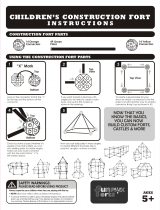
Product description
Pole assembly consists of three poles and a
common duct.
Each pole comprises of a vacuum bottle, current
transfer contacts and an insulating pull rod placed in
the porcelain housing.
Robust housing for protection against fire and
hazardous conditions.
Primary terminal connectors can be provided,
such as NEMA 4.
All three poles are mounted on a common duct.
Poles are interconnected with each other as well
as to the operating mechanism with a linkage
arrangement.
Simple design - minimises spare parts.
1. Top terminal
2. Arc chamber insulator
3. Vacuum interrupter
4. Bottom terminal
5. Insulating rod
6. Support insulator
7. Bottom crank housing
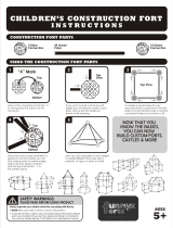
Description
Medium Voltage circuit-breaker type VBF, with operating mechanism type ESH.
1.1 Design of the circuit-breaker 1. Pole assembly
The circuit-breaker is made up of three separate poles.
These consist of three main parts.
1. Pole assembly
2. Cabinet with operating mechanism
3. Steel structure
Sectional view of pole part
Rear view with back cover open

4
Product description
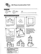
2. Cabinet with operating mechanism
2.1 Base Cabinet
The base cabinet is made of painted mild steel. The
cabinet houses a spring operated mechanism which
is mechanically linked to all three poles. The cabinet
also includes the followings:
Anti-condensation heater
Circuit breaker status indicator
Mechanical operation counter
Breaker control switches
Anti-pumping relay
AC / DC fuses
Auxiliary wiring
Terminal blocks
2.2 Operating mechanism
For high operational reliability and minimal maintenance,
a simple and robust spring operated mechanism is used.
Features
O-C-O operation without recharging
Closing spring is charged by motor in less than
15 secs.
Mechanical / electrical anti-pumping
Provision for manual charging
Suitable for high speed auto-reclosing
Manual closing and tripping arrangement
Mechanical ON - OFF and SPRING CHARGED
indication
Auxiliary switch: 13 NO + 13 NC
Additional tripping solenoid(optional)
Operating mechanism with electrical accessories
3. Structure
The breaker is supplied with galvanised steel strucutre, if ordered, which supports the breaker on the foundation
4. Standards
The circuit breakers comply with the requirements according to IEC and are restrike-free when breaking a
capacitive load.

5
1.0 Packing Information, Goods marking & Transport
1.1 Goods marking
1.2 Documents
1.3 Transport
1.4 Lifting
2.0 Receipt & storage prior to installation
2.1 General
2.2 Receipt & storage of breaker
3.0 Safety provisions and assembly instructions
3.1 Warning texts
3.2 Safety Precaution
PART A Receipt, Storage & Safety

6
1.0 Packing Information, goods marking &
transport
1.1 Goods marking
The circuit-breaker is transported in seaworthy packing
in ‘OPEN’ position in two parts (in most of the cases).
The poles with duct is packed in one case and the
control cabinet is packed in the other.
The breaker structures (if part of the order) are packed
separately.
The CT structures (optional item) are packed
separately.
Each case is marked with case markings on two sides
with indelible black ink. The case markings include
information of case number, gross weight, etc.
In addition to the above, the cases are marked with
the following symbols. These should be observed
when choosing lifting equipment.
1.2 Documents
Following documents are packed with breaker:
Instruction manual
Test certificates
Drawings
Packing list
This way up Fragile, handle
with care
Keep dry Keep away
from heat
Legend on packing case
PART A Receipt, Storage & Safety
Use no hook
No hand truck
here
Stacking
limitation
Do not roll
kg max

7
1.3 Transport
The circuit- breakers shall be transported in packed
condition only. Following precautions are to be
taken while transporting:
Ensure that packing cases are not placed on
wet surfaces / waterlogged areas.
Breakers should not be stacked one over the
other.
Lifted by a lifting device equipped with forks or
slings. If a crane is used, slings shall be used. The
units must not be rolled or dropped.
1.4 Lifting
Before lifting the case, observe the information on it
(such as symbol, weight, etc.). The cases shall be
Lifting the case
PART A Receipt, Storage & Safety
Duct with pole
Cabinet Structure
Loose structure(optional)
1500
2110
260
1730
620
900
1340
Case marking

8
2.0 Receipt & Storage prior to installation
2.1 General
The breaker with complete packing should always
be stored indoor to protect from direct sunlight
& rain/snow.
Breakers can be stored upto 3 months from date
of shipment from the factory. For longer storage,
the packing needs to be removed and the breaker
be kept under controlled environmental conditions.
We define storage in controlled conditions as a
place with :
Leak proof roof
Solid, flat ground
Relative humidity less than 50%
Temperature 20°C (± 10° C)
2.2 Receipt & Storage of Breaker
Each delivery, on receipt, should be checked
for:
Shortages and discrepancies. (Check
against order and delivery documents).
Any transit damage and material losses.
Abnormality, if any, must be notified
immediately to: ABB, forwarding agents
and the insurance company.
The operating cabinet should be unpacked on arrival.
If it is not going to be stored in an approved storage
the heating elements must be connected
permanently to the electric supply to protect the
control equipment from corrosion or freezing damage.
The breaker with duct & poles should be stored in their
original transport units, where they are well protected
from damage. The breakers if stored outdoors, should
be well covered with tarpaulin. The tarpaulin should
not be placed directly on breaker. An air gap should
be left to prevent condensation.
The minimum allowed ambient temperature for the
Outdoor Vacuum Circuit Breaker is (-)30°C.
Structures may be stored outdoors.Spare parts should
be stored indoors in a recommended storage area
in their original packings.
PART A Receipt, Storage & Safety

9
3.0 Safety provisions for circuit-breaker
The entire assembly instruction should be read carefully before starting the assembly work.
3.1 Warning texts
Warning texts are stated in 5 different degrees of urgency, which should be carefully observed.
These are described below:
DANGER indicates an immediate risk situation that can lead to death
or serious personal injury if not avoided.
Warning indicates a risk situation that can lead to death or serious
personal injury if not avoided.
Caution indicates a risk situation that can lead to small or moderate
damage
Note is used when there is danger that can lead to equipment
damage only
Important indicates an operation or a suggestion for handling
DANGER
!
!
!
Note
Warning
Caution
Important
PART A Receipt, Storage & Safety

10
2) Work on ladders and platforms The work shall follow the directions
of the authority for occupational
safety and health. Avoid work in
severe weather conditions, which
entails a great deal of climbing for
short periods.
3) Work with low- voltage.
Both D.C. and A.C. Voltage
may be drawn to the operating
device.
4) Risk in operating mechanism
and link system
The spring operated device has
energy stored in the operating
spring, when it is in charged
condition. The device can be
activated by heavy vibrations or
unintentional, slight touch on
mechanical latch parts.
5) Work on pressurized porcelain
Insulators.
Normally, the work pressure is
up to 1.5 bar absolute. Damages
in the porcelain can cause risk of
the porcelain breaking.
Do not connect control supply and
heater voltage until all connection
work is completed.
Warning plate is placed on the
supporting frame.
No work must be carried out unless
the closing and opening springs are
discharged, the circuit-breaker is in
position OFF “0” and the supply to
the motor is disconnected.
The operating mechanism must not
be operated unless it is connected to
the circuit
Work close to the insulators of the
circuit breaker that entails risk of
porcelain damage must not be
carried out until the gas pressure has
been lowered to 1.0 bar absolute
pressure.
3.2 Safety Precaution
When working on high-voltage circuit breaker the below-mentioned risk must be taken
into consideration and corresponding safety measures taken.
RISK SAFETY MESAURES
1) Work next to high voltage Warning plate is placed inside the
door of the operating device.
Disconnect all electrical supply. Connect
earthing devices near the workplace.
If work must be carried out near
energized parts of the plant, it has to
follow local safety regulation of the
organization responsible for the circuit
breaker.
PART A Receipt, Storage & Safety

11
General
1.0 Technical details
1.1 Type designation
1.2 Specifications
1.3 Rating plate
2.0 Breaker details
3.0 Function
3.1 Switching operations
3.2 Closing operation
3.3 Opening operation
4.0 Installation
General
4.1Preparations
4.2 Installation procedure
4.2.1 Installation of breaker with
cabinet attached to the pole duct
4.2.1.1 Unpacking of structure
4.2.1.2 Various parts of structure
assembly
4.2.1.3 Assembly sequence for
structure
4.2.1.4 Dismantling of cases
4.2.1.4.1 Unpacking of
cabinet
4.2.1.4.2 Unpacking of
duct & Pole
assembly
4.2.1.5 Assembly of duct with poles
on cabinet
4.2.1.6 Assembly of entire circuit
breaker on structure
4.2.2 Installation of breaker with cabinet
at lower height
4.2.2.1 Various parts of structure
assembly
4.2.2.2 Unpacking of structure
4.2.2.3 Assembly sequence for structure
4.2.2.4 Unpacking of duct & pole
assembly
4.2.2.5 Dismantling of cases
4.2.2.5.1 Unpacking of cabinet
4.2.3 High voltage connections
4.2.4 Low voltage connections
4.2.5 Earthing
5.0 Commissioning
5.1 General procedure
5.2 Space heaters
5.3 Starting conditions
5.4 Function test
5.5 Trial switching operations
5.6 Anti-pumping device
5.7 Check of heaters
5.8 Concluding work
6.0 Periodical checks
6.1 General
6.2 Checking programme
6.3 General Inspection of the circuit
breaker
PART B Installation, Operation & Maintenance

12
General
1.0 Technical details
This operating instruction is applicable for Outdoor circuit Breaker type VBF.
1.1 Type designation VBF 36 16 25
Outdoor Vacuum Circuit Breaker
Type VBF
Rated voltage –
Rated normal current -
Rated breaking capacity – 26.3kA
24 for 24kV
36 for 36kV
12 for 1250 Amp
16 for 1600 Amp
1.2 Specifications
1.3 Rating plate
Type VBF 36
Standard IEC – 62271-100
Rated voltage 36kV
Frequency 50 Hz
Insulation level 70/170kVp.
Normal current 1250 / 1600 Amps.
Short circuit breaking current 26.3 kA
Operating sequence 0-0.3S-CO-3 Min.-CO
Weight 800 kg.
PART B Installation, Operation & Maintenance

13
2.0 Breaker details
The circuit breaker type VBF is a three pole
vacuum circuit breaker and designed in a
column type construction with “spring stored
energy operating mechanism” as shown in
Standard General Arrangement drawing
(refer Fig.1a, b & c)
3.0 Function
The standard schematic circuit diagram of the
breaker shown in Fig.3 (please refer order bound
drawings for details)
3.1 Switching operations
As supplied from ABB the circuit breaker will be
in open position and closing spring in
discharged condition. When the control supply
3.3 Opening operation
To open the circuit breaker, the "OPEN" control
element is actuated either electrically
through the opening coil or mechanically through
push button arrangement. This enables the spring
stored energy mechanism to release the spring
energy through the linkage system, which rotate the
common shaft in opposite direction. This rotation
forces the moving contact of all the poles to move
downward, opening the circuit breaker.
is given to the breaker, closing spring will get
charged automatically by means of spring
charging motor.
3.2 Closing operation
To close the circuit breaker the “CLOSE" control
element is actuated either electrically through
the closing coil or mechanically through
Breaker Pole
The breaker pole consists of (ref. Fig.2)
10001 - Insulator body
10200 - Vacuum interrupter
10017 - Lamellar contact
10502 - Current collecting hub
10008 & 10500 - Upper and lower terminal
10300 - Insulating Rod
10401 - Crank Housing
The poles are filled with SF6 or Nitrogen gas
individually at a pressure of 1.5 bar (abs).
(Nitrogen can be provided on request)
push button arrangement. This enables the,
spring stored energy mechanism to release the
spring energy, through the linkage system,
which rotate the common shaft. The rotation of
the common shaft moves the moving contact of
all the poles upward through the operating stud,
closing the circuit breaker. This movement also
exerts the required contact pressure on the
moving contact.
General
As supplied from ABB the circuit breaker are
complete in all respect with all the necessary
settings for smooth and trouble free operations
of the circuit breaker All the moving parts of
the circuit breaker are positioned correctly and
coupled together and they are well secured
with the fasteners.
4.0 Installation
It is recommended to use standard tools and
standard practices for lifting and transport of the
circuit breaker at time of installation so as to avoid
mechanical damage of the pole parts. In general the
unpacking and lifting of the circuit breaker shall
be done as explained and given in clause 4.2.
PART B Installation, Operation & Maintenance

14
4.1 Preparations
The following are to be made available --
An erection crane with a load carrying capacity of
about 1500 kg, and a crane hook with height of at
least 4 m (= 13 feet) above the floor.
Lifting ropes.
Dimension drawings, installation drawings,
wiring and circuit diagram.
Torque wrench for a range of 6-100 NM
Circlip pliers.
Commercially available set of open and ring
spanners size from 7 mm to 43 mm.
Cleaning and working material like cloth etc.
Conducting grease.
Spirit level.
4.2 Installation procedure
4.2.1 Installation of Breaker with cabinet
attached to the pole duct
Circuit Breaker can be transported in three
parts as explained below.
1 Cabinet with Spring-Mechanism Drive &
Electrical wiring & apparatus.
2 Duct-with-Poles and the inter-pole-links.
3 Structure Assembly
4.2.1.1 Unpacking of structure
Place the case horizontally on a flat surface before
opening the cover.
Check that all parts are included in the delivery.
Check the packing list.
Check that no parts have been damaged during
transport; especially the porcelain insulators.
Report any faults immediately to the ABB
representative.
Before delivery, both Tripping and Closing Springs are
discharged and Circuit Breaker kept in OPEN position.
Before starting installation ensure that foundation with
Foundation Bolts as per drawing is ready [Refer Fig.1a,
1b & 1c].
In some cases CB is transported in two cases
1. Complete CB
2. Structure assembly.
4.2.1.2 Various parts of Structure assembly:
List of the parts of structure
1. Upper Leg Assly- 2 Nos.
2. Lower Legs Assly – 2Nos
3. Support Angles(front and rear) 2 Nos
4. Stiffeners – 2Nos
5. Cross-Angles. – 4 Nos
6. Foundation Bolts- 4 Nos [2 Nos
Additional for CT structure ]
List of the additional parts for CT structure
7. Upper Leg Assly – 2Nos
8. Lower Leg Assly – 2 Nos
9. Support Angles – 2 Nos
10. C-Channel for C.T/P.T.- 1 No
11. Cross Angles – 2 Nos.
One Spanner each [open & ring] of size 18x19
& 24x27 needed to assemble the structure
Parts of structure assembly
PART B Installation, Operation & Maintenance
10
7
8
11
9
9
1
3
5
2
6
5
4

15
4.2.1.3.
Assembly sequences for Structure :
Arrangement without CT structure
Fix the Lower Leg Assembly as shown
Fix M20 Plain Washer, Spring Washer & Hex nut or Expansion Bolts in case the
foundation is with expansion Bolts.
Keep Nuts slightly loose for flexibility during entire assembly of structure,
Fix Lower Legs of CT Structure Assembly [optional]
Arrangement with CT Structure [Optional]
Circuit Breaker Structure Assembly
Now fix Cross-Support Angles (5) as shown using M12 bolts,
spring washers, plain washers & Hex Nus .
Slide Upper Leg Assembly (1) into Lower Leg Assembly to
Fix Support Angles(3) as per the order bound GA drawing
For the sake of flexibility, do not fully tighten the fasteners.
1
3
5
and M12 bolts, spring washers, plain washers & Hex Nuts.
PART B Installation, Operation & Maintenance
Fix the Lower Leg Assembly as shown.
Fix M20 Plain Washer, Spring Washer & Hex nut
or Expansion Bolts in case the foundation is with
Keep Nuts slightly loose for flexibility during entire
Expansion bolts.
Assembly of structure.
achieve height

16
Slide Upper Leg (7) in Lower Leg assembly & assemble using
M12 bolts, spring, washers, plain washers & Hex Nuts.
Fix Support-Angles(9) on Upper Leg Assembly(1) & (7) as
Fix Cross-Angles (11)
Fix CT Frame(10) on the Support Angles(9)
For the sake of flexibility, do not fully tighten the fasteners.
1
9
1
9
10
7
1
1
1
1
Shown
Circuit-breaker Structure Assembly with CT structure
4.2.1.4 Dismantling of Cases
4.2.1.4.1 Unpacking of Cabinet
Cabinet Assembly on palate
Remove top & all side covers of casing containing Cabinet
Do not remove the bottom pallet.
Assembly.
Remove Vacuum sealing
PART B Installation, Operation & Maintenance

17
4.2.1.4.2 Unpacking of Duct & Pole Assembly
Unpacking of Poles-with-Duct Assembly
Remove hardware only
after holding the assembly
by crane
Remove top & all side covers of casing containing
Hold Poles-with-Duct Assembly by lifting crane as
Remove the M8 Bolts from the rear covers of the
Remove bolts fixed to the bottom packing pallet.
Lift entire assembly, match 4 holes with cabinet
Poles-with-Duct assembly.
Remove Vacuum sealing.
as shown.
Duct & open the rear cover.
and place it slowly on the cabinet.
Assemble Duct with
Cabinet using M12
bolts
Remove Bolts from bottom
after assembly of Duct &
Cabinet is over
4.2.1.5 Assembly of Duct-with-Poles on Cabinet :
Assembly of Poles-with-Duct & Cabinet
Assemble Poles-with-Duct & Cabinet together
Remove the bolts from the pallet as shown
the Cabinet]
Lift the entire assembly to the ready structure.
using M12 bolts, spring washers. M12 nut are
welded to the cabinet
[Bolts can be removed without opening
PART B Installation, Operation & Maintenance

18
PART B Installation, Operation & Maintenance
4.2.1.6 Assembly of entire Circuit-Breaker on structure
Refer figure below before going for assembly.
Slowly lower the Circuit-Breaker in such a way that the Cabinet enters inside the Upper
Leg Assemblies & rests on the support angles & the Duct rests on the Upper Leg
Assemblies of structure.
Ensure that stiffener plates are placed inside the duct and assemble with structure.
Engage Cabinet with the support angles. Fix M12 bolts, spring washers, plain washers
from bottom of the support angles. [M12 Nuts are welded inside the cabinet]
This completes the assembly.
Now fasten all hardware; do not remove slings until all hardware are fastened fully.
Fixing the Breaker on the structure
Fix Cabinet with Duct
Assembly on support-
angles & fix M12 bolts,
washer & Spring
Washer from bottom
Ensure that stiffener
plates are placed
inside the duct.

19
PART B Installation, Operation & Maintenance
Connection of Driving-Link with composite-lever:
These figures are of Y-pole
Remove the pin and U-Clip from the
lever arm
Rotate the Composite-Lever such that the
hole of the lever-arm matches with the hole in
Driving Link & insert the pin
Insert the Pin from back and put U-Clip
This completes the assembly.
Now fasten all the hardware.
Remove the lifting-ropes & wooden blocks.
Carry out pre-commissioning tests as
Described in Commissioning section.
Sequence - 1
Sequence - 2
Sequence - 3

20
PART B Installation, Operation & Maintenance
4.2.2 Installation of Breaker with cabinet
at lower height
Circuit Breakers are be transported in three
parts as explained below.
1 Cabinet with Spring-Mechanism Drive &
Electrical wiring & apparatus.
2 Duct-with-Poles and the inter-pole-links.
3 Structure Assembly and connecting drive
link & pipe assemblies.
Before delivery, both Tripping and Closing Springs are
discharged and Circuit Breaker kept in OPEN position.
Following additional items are supplied
and to be used for installation of control cabinet
at lower height:
Extended Drive-link
Special pin for setting
Cover for driver-link
Top support angle
Before starting installation ensure that foundation with
Foundation Bolts as per drawing is ready (Refer Fig.1a,
1b & 1c on page 47, 48 & 49).
4.2.2.1 Various parts of Structure assembly:
List of the parts of structure
1. Upper Leg Assly- 2 Nos.
2. Lower Legs Assly – 2Nos
3. Top Support Angles(front and rear) 2 Nos
5. Stiffeners – 2Nos
6. Cross-Angles. – 4 Nos
7. Foundation Bolts- 4 Nos [2 Nos
Additional for CT structure ]
List of the additional parts for CT structure
8. Upper Leg Assly – 2Nos
9. Lower Leg Assly – 2 Nos
10. Support Angles – 2 Nos
11. C-Channel for C.T/P.T.- 1 No
12. Cross Angles – 2 Nos.
One Spanner each [open & ring] of size 18x19
& 24x27 needed to assemble the structure
Parts of structure assembly
4. Bottom Support Angles(front and rear) 2 Nos
11
8
9
5
12
9
10
1
3
2
7
4
6
6
/