Gemini PS-646 PRO2 User manual
- Category
- Audio mixers
- Type
- User manual
Page is loading ...
Page is loading ...

Page 3
Introduction
Congratulations on purchasing the Gemini PS-646 PRO2 mixer. This state
of the art mixer is backed by a three year warranty, excluding crossfader
and channel slides. Prior to use, we suggest that you carefully read all the
instructions.
Features
• 4 Stereo Channels
• State of the Art Cue Section
• 1 Phono/Line Convertible, 2 Phono, 5 Line, and 2 Mic Inputs
• Cut Feature for Bass, Mid and High for each channel
• Gain, High, Mid and Bass tone controls for each channel
• Beat Indicators
• Talkover
• Balanced and Unbalanced Master Outputs
• Booth Output
• Dual mode display
Cautions
1. Always test equipment before rack mounting. Retain a copy of your
sales receipt for warranty purposes.
2. All operating instructions should be read before using this equipment.
3. To reduce the risk of electrical shock, do not open the unit. There are
NO USER REPLACEABLE PARTS INSIDE. Please refer servicing to a
qualified service technician.
In the U.S.A., if you have any problems with this unit,
call 1-732-969-9000 for customer service. Do not return
equipment to your dealer.
4. Do not expose this unit to direct sunlight or to a heat source such as a
radiator or stove.
5. This unit should be cleaned only with a damp cloth. Avoid solvents or
other cleaning detergents.
6. When moving this equipment, it should be placed in its original carton
and packaging. This will reduce the risk of damage during transit.
7. DO NOT EXPOSE THIS UNIT TO RAIN OR MOISTURE.
8. DO NOT USE ANY SPRAY CLEANER OR LUBRICANT ON ANY
CONTROLS OR SWITCHES.
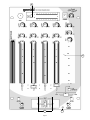
Connections
1. Before plugging in the power cord, make sure that the VOLTAGE
SELECTOR (38) switch is set to the correct voltage.
NOTE: This product is double insulated and not intended to
be grounded.
2. Make sure that the POWER (1) switch is in the off position.
3. The PS-646 PRO2 is supplied with 2 sets of amp output jacks. The
MASTER BALANCED OUTPUT (39) jacks are used to connect to your
main amplifier using standard XLR cables. We recommend using the
balanced amp outputs if the cables to your amp are 25 feet or more.
Balanced outputs have three separate conductors, two of which are
signal (positive and negative) and one shield (ground). Pin 1 is ground
(shield). Pin 2 is signal hot (positive). Pin 3 is signal cold (negative).
The OUTPUT AMP (40) jacks are unbalanced and used to connect to
your main amplifier. The OUTPUT BOOTH (41) jacks allow you to hook
up an additional amplifier.
4. The MIC 1 (3) input (found on the front panel) accepts an XLR
connector.
The MIC 2 (50) input (found on the rear panel) accepts 1/4"
connectors. Each accept balanced and unbalanced microphones.
5. On the rear panel are 1 stereo PHONO/LINE (49) input, 2 stereo
PHONO (45, 47) inputs, and 5 stereo LINE (42, 43, 44, 46, 48) inputs.
The PHONO/LINE SWITCH (51) enables you to set the (49) input to
Phono or Line. The phono inputs will accept only turntables with a
magnetic cartridge. A GROUND SCREW (52) for you to ground your
turntables is located on the rear panel. The stereo line inputs will
accept any line level input such as a CD player, a cassette player, etc.
6. Headphones can be plugged into the front panel mounted
HEADPHONE (2) jack OR headphones can plugged into the
HEADPHONE (23) jack located on the side of the mixer.
Using the Ground Lift Switch
Depending on your system configuration, sometimes applying the ground
will create a quieter signal path. Sometimes lifting the ground can
eliminate ground loops and hum to create a quieter signal path.
1. With the mixer on, listen to the system in idle mode (no signal present)
with the ground applied (the GROUND LIFT SWITCH (53) in the left
position).
2. Then turn the power off before moving the GROUND LIFT SWITCH
(53). Lift the ground by moving the GROUND LIFT SWITCH to the
right, turn the power back on and listen to determine which position will
provide a signal devoid of background noise and hum. Keep the
GROUND LIFT SWITCH in the ground position if the noise level
remains the same in either position.
CAUTION: DO NOT TERMINATE THE AC GROUND ON THE POWER
MIXER IN ANY WAY. TERMINATION OF THE AC GROUND CAN BE
HAZARDOUS.
Operation
1. POWER ON: Once you have made all the equipment connections to
your mixer, press the POWER SWITCH (1).
2. CHANNEL 1: The GAIN (4), HIGH (5), MID (6), and LOW (7) controls
allow you to fully adjust the selected source. Switch # (9) allows you to
select the PHONO 1/LINE 1 (49) or the LINE 2 (48) input. The
CHANNEL SLIDE (10) controls the input level of this channel.
3. CHANNEL 2: The GAIN (4), HIGH (5), MID (6), and LOW (7) controls
allow you to fully adjust the selected source. Switch # (11) allows you
to select the PHONO 2 (47) or the LINE 3 (46) input. The CHANNEL
SLIDE (12) controls the input level of this channel.
4. CHANNEL 3: The GAIN (4), HIGH (5), MID (6), and LOW (7) controls
allow you to fully adjust the selected source. Switch # (13) allows you
to select the PHONO 3 (45) or the LINE 4 (44) input. The CHANNEL
SLIDE (14) controls the input level of this channel.
5. CHANNEL 4: The GAIN (4), HIGH (5), MID (6), and LOW (7) controls
allow you to fully adjust the selected source. Switch # (15) allows you
to select the LINE 5 (43) or the LINE 6 (42) input. The CHANNEL
SLIDE (16) controls the input level of this channel.
NOTE: There is Low, Mid and High equalization for each
channel with an extremely wide range of adjustment.
SUGGESTION: You can use the Cut Features on each channel to
remove Low, Mid and/or High to create special effects.
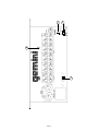
6. CROSSFADER SECTION: The CROSSFADER (22) allows the mixing of
one source into another. The PS-646 PRO2 features an assignable
crossfader. The ASSIGN (19, 20) switches allow you to select which
channel will play through each side of the crossfader. The ASSIGN (19)
switch has 4 settings (1, 2, 3 or 4) and allows you to select channel 1, 2,
3 or 4 to play through the left side of the crossfader. The ASSIGN (20)
switch has 4 settings (1, 2, 3 or 4) and allows you to select channel 1, 2,
3 or 4 to play through the right side of the crossfader. There are two OFF
(17, 18) buttons for the crossfader. When the OFF (17) button is
pressed, the left side of the crossfader will be inactive. When the OFF
(18) button is pressed, the right side of the crossfader will be inactive.
Using the OFF button, be sure to deactivate the crossfader before

Page 4
changing the ASSIGN setting. This will avoid any click or popping sound
in your signal while you are changing the assign setting. The
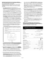
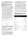
CROSSFADER (22) in your unit is removable and if the need arises can
be easily replaced. Crossfader units are available in three varieties. Part
# RF-45 (which is identical to the crossfader supplied with the mixer) has
a 45 mm travel from side to side. Part # RF-30 is available with a 30 mm
travel distance. Also available is the PSF-45 with a special curve
designed for scratch mixing. Just purchase one of these crossfader units
from your Gemini dealer and follow these instructions:
1. Unscrew the outside FADER PLATE SCREWS (B). Do not
touch the INSIDE SCREWS (C).
2. Carefully lift the fader and unplug the CABLE (D).
3. Plug the new fader into the cable and place it back in the
mixer.
4. Screw the fader to the mixer.
7. BEAT INDICATORS: Each side of the CROSSFADER (22) has it’s own
BEAT INDICATOR (21). They flash at the low frequency peak level
allowing you to match the beats visually.
8. OUTPUT CONTROL SECTION: The level of the AMP OUT (39, 40) is
controlled by the MASTER (32) and the BALANCE (31) controls. The
BOOTH (30) control adjusts the level of the BOOTH OUTPUT (41).
HINT: The booth OUTPUT is used by some DJs to run monitor
speakers in their DJ booth. You can also use it as a second ZONE or
AMP output.
9. TALKOVER SECTION: The purpose of the talkover section is to allow
the program playing to be muted so that the mic can be heard above
the music. The MIC/TALKOVER SWITCH (28) controls MIC 1 and MIC
2 and has three settings. When the MIC/TALKOVER SWITCH (28) is
in the left position, MIC 1 and MIC 2 and talkover are off. When the
MIC/TALKOVER SWITCH (28) is in the center position MIC 1 and MIC
2 are on, the MIC INDICATOR (29) will glow, but talkover is off. When
the MIC/TALKOVER SWITCH (28) is in the right position, MIC 1 and
MIC 2 and talkover will be on and the volume of all sources except the
Mic inputs are lowered by 16 dB. The TREBLE (24) and BASS (25)
controls allow you to fully adjust the tone of MIC 1 and MIC 2. MIC 1
LEVEL (26) controls the level of MIC 1. The MIC 2 LEVEL (27)
controls the level of MIC 2.
10.CUE SECTION: By connecting a set of headphones to the
HEADPHONE (2 OR 23) jack, you can monitor any or all of the
channels. Press the CUE ASSIGN (8) buttons for channels 1 - 4 to
select the channel or channels to be monitored and their respective
LED indicators will glow. Use the CUE LEVEL (33) control to adjust the
cue volume without effecting the overall mix. By sliding the CUE PAN
(35) control to the left you will be able to monitor the assigned cue
signal. Sliding to the right will monitor the PGM (program) output.
Activating the multifunction CUE X-F SPLIT (34) converts the CUE
PAN (35) control so that it fades between the two channels assigned to
the crossfader and splits the signals so that the left side will be heard
in the left headphone and the right side will be heard in the right
headphone.
11. DISPLAY: The peak hold, dual function DISPLAY (36) indicates either
the MASTER (39, 40) output left and right levels OR the the selected
cue and program (premaster output) levels. You can choose the option
you want by pressing the DISPLAY (37) button.
NOTE: When the DISPLAY (36) is in the cue/program mode,
by adjusting the individual channel level slides, you can
increase or decrease the signal to match the other
channels signal.
Specifications
INPUTS:
Phono.........................................................................3mV 47Kohm
Line.......................................................................150 mV 27Kohm
Aux.......................................................................150 mV 27Kohm
OUTPUTS:
Amp/Booth......................................................0 dB 1V 400ohm
Max..............................20V Peak to Peak
Rec...........................................................................225mV 5Kohm
MIC 1 & MIC 2:
DJ Mic....................................................1.5mV 2Kohm balanced
Bass......................................................................................± 12dB
High.......................................................................................± 12dB
GENERAL:
Low (Chnls 1-4).......................................................+ 12dB/- 32 dB
Mid (Chnls 1-4)..........................................................+ 12dB/- 32 dB
High (Chnls 1-4).....................................................+ 12dB/- 32 dB
Gain (Chnls 1-4)..............................................................0 to -20dB
Frequency Response....................................20Hz - 20KHz +/- 2dB
Distortion................................................................................0.02%
S/N Ratio...............................................................better than 80dB
Talkover Attenuation..............................................................-16dB
Headphone Impedance.........................................................16ohm
Power Source.............................................115/230V 50/60Hz 10W
Dimensions...........................................10”w x 14”d x 4.5”h
254 x 355 x 120 mm
Weight........................................................................8.5 lbs (3.86 kg)
Page is loading ...
Page is loading ...
Page is loading ...
Page is loading ...
Page is loading ...
Page is loading ...
Page is loading ...
Page is loading ...
-
 1
1
-
 2
2
-
 3
3
-
 4
4
-
 5
5
-
 6
6
-
 7
7
-
 8
8
-
 9
9
-
 10
10
-
 11
11
-
 12
12


Gemini PS-646 PRO2 User manual
- Category
- Audio mixers
- Type
- User manual
Ask a question and I''ll find the answer in the document
Finding information in a document is now easier with AI
in other languages
- italiano: Gemini PS-646 PRO2 Manuale utente
- français: Gemini PS-646 PRO2 Manuel utilisateur
- español: Gemini PS-646 PRO2 Manual de usuario
- Deutsch: Gemini PS-646 PRO2 Benutzerhandbuch
Related papers
Other documents
-
Vivanco MX 660 User manual
-
Akiyama MC-Club User manual
-
Omnitronic EM-760 User manual
-
Numark DXM03 User manual
-
JBSYSTEMS LIGHT CONTROL 5.2 Owner's manual
-
IMG Stage Line MPX-622/SW User manual
-
-
-
BEGLEC BPM6usb Owner's manual
-