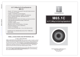
DCM Speakers C520 User manual

Category
Soundbar speakers
Type
User manual

This manual is also suitable for

21A3805
OWNERS MANUAL
FIRST
CLASS
STAMP
HERE
7676 S. 46th Street
PHOENIX AZ 85040-6400
C520 / C625 / C825
CONGRATULATIONS
We appreciate your choice of DCM In-Ceiling Loudspeakers. Properly installed
and operated, DCM In-Ceiling Loudspeakers should provide years of worry-free
listening pleasure. It’s important that you follow each step in this guide carefully
to insure proper installation. If you have any questions regarding DCM In-Ceiling
Loudspeakers, please call us at 1-877-DCM-LOUD.
SPECIFICATIONS C520 C625 C825
Frequency Response 60Hz-20kHz 50Hz-20kHz 40Hz-20kHz
+/- 3dB +/- 3dB +/- 3dB
Impedance 8 Ohms 8 Ohms 8 Ohms
Power Handling 50 Watts RMS 55 Watts RMS 60 Watts RMS
100 Watts Total 110 Watts Total 120 Watts Total
Sensitivity (1W/1m) 85dB 85dB 85dB
Woofer Diameter 5-1/4” 6-1/2” 8”
Tweeter 20mm 25mm 25mm
Soft Dome Soft Dome Soft Dome
Crossover Frequency 4kHz 3kHz 2.5kHz
Mounting Depth 3-1/2” 2-15/16” 3-3/8”
Baffle Diameter 7-27/32” 9” 10-3/4”
PAINTING YOUR DCM IN-CEILING
DCM In-Ceiling speakers are designed to accept all types of interior and exterior
paints. Spray or roller application should provide excellent results. A paint shield
is included with all DCM In-Ceiling speakers to protect the speakers during the
painting process.
TEN YEAR LIMITED WARRANTY
DCM In-Ceiling Loudspeakers are guaranteed against defects in parts and
workmanship for a period of ten (10) years from the date of purchase. Speakers
found defective during that period will be repaired by DCM without charge for
parts.This warranty extends to the original purchaser from an authorized DCM
retailer only.
This warranty does not extend to equipment damage due to negligence, mis-
use, improper installation, shipping damage, abuse or accident.This warranty is
void if it is determined that unauthorized parties have attempted repairs or alter-
ations of any nature.
Defective parts will be repaired, adjusted or replaced with no charge for
materials or labor if the purchaser returns the speaker together with the original
sales receipt or other proof of purchase at the purchaser’s expense to DCM, 282
Carver Street, Winslow, IL. 61089. No implied warranties shall extend beyond ten
years from the original date of purchase. Incidental and consequential damages
are expressly excluded from this warranty and may not be recovered by a pur-
chaser as a result of breach of any warranty.
The attached warranty card must be filled out and mailed within 10 days of
purchase to validate warranty. Retain the top portion for your records.
Specifications subject to change without notice.
MODEL# _______________________________
NAME _____________________________________________________________________________
STREET ___________________________________________________________________________
CITY _____________________________________ STATE _____________ ZIP _________________
DATE PURCHASED _________________________
PLACE PURCHASED ________________________________________________________________
Purchased as a: Packaged System ( ) Replacement System ( )
Speakers Only ( ) Extension Speakers ( )
If replacement, what is the name and model number of the system replaced?
Name ____________________ Model# ____________________
What other Brands did you consider? _______________________ _______________________
_______________________ _______________________ _______________________
Why did you purchase DCM speakers?
Sound ( ) Price ( ) Dealer Recommendation ( ) Other ( )
Comments _____________________________________________________________________
(This registration must be filled out and mailed within 10 days of purchase to validate warranty.)
WARRANTY REGISTRATION
LOUDSPEAKER PLACEMENT
DCM In-Ceiling Loudspeakers are designed to work within any interior decorat-
ing scheme. They can be installed in virtually any location where flush mounting
is possible. To maximize their sound performance however certain guidelines
should be followed. For the best stereo reproduction the two loudspeakers
should be placed an equal distance from your listening position and separated so
that the angle between them, at the listening position, is between 40 and 60
degrees.
TWEETER LEVEL ADJUSTMENT
The output of the tweeter can be adjusted to compensate for speaker place-
ment/listening positions that are less than ideal. The 0dB position is designed to
provide the smoothest frequency response on axis. If the high frequency
response is considered to be too strong or too weak, the tweeter level can be
increased (+3dB position) or decreased (-3dB position) to suit the listeners pref-
erence.
W625
6-1/2” Two-Way InWall Speaker
25mm Soft Dome Swivel Tweeter
Impedance: 8 ohms
Sensitivity:85dB
55 Watts RMS/110 Watts Total
Frequency Response: 48Hz-20kHz
12”H x 8-5/8”W x 3-1/4”D
DCM6
6-1/2” Two-Way Home Loudspeaker
Impedance: 8 ohms nominal
Sensitivity: 89dB
75 Watts RMS/150 Watts Total
Frequency Response: 58Hz-20kHz
12.992”H x 7.992”W x 7.795”D
DCM10
10” Two-Way Home Loudspeaker
Impedance: 8 ohms nominal
Sensitivity:94dB
200 Watts RMS/400 Watts Total
Frequency Response:35Hz-20kHz
31.312”H x 15.825”W x 12.501”D
W825
8” Two-Way InWall Speaker
25mm Soft Dome Swivel Tweeter
Impedance: 8 ohms
Sensitivity: 86dB
60 Watts RMS/120 Watts Total
Frequency Response: 36Hz-20kHz
14”H x 10”W x 3-1/2”D
DCM6C
6-1/2” Center Channel Loudspeaker
Impedance: 8 ohms nominal
Sensitivity:89dB
75 Watts RMS/150 Watts Total
Frequency Response: 58Hz-20kHz
7.992”H x 19.685”W x 7.204”D
DCM12
12” Two-Way Home Loudspeaker
Impedance:8 ohms nominal
Sensitivity:97dB
250 Watts RMS/500 Watts Total
Frequency Response:30Hz-20kHz
33.312”H x 17.638”W x 15.938”D
OTHER PRODUCTS FROM DCM
InWall Loudspeakers
Home Loudspeakers
STEP 1
Using a stud finder (available at low cost at most hardware stores) or other accu-
rate method, locate center point between two joists and mark. Using template pro-
vided, trace hole pattern on surface of ceiling.
STEP 2
Using a sabre saw, keyhole saw or very sharp utility knife, cut hole in wall, fol-
lowing traced pattern.
STEP 3
Run loudspeaker wires to sound source location. There are several methods you
can use to accomplish wiring,depending on the construction characteristics of the
room or house. You can add a professional touch to your installation by using a
speaker terminal plate at the source location. Leave sufficient amount of wire at
speaker location (8 to 10 inches) to complete connection.
STEP 4
Attach loudspeaker wires to speaker terminals, observing correct polarity, and
position speaker frame up into cutout. Be careful not to pinch wires in the process.
STEP 5
Carefully tighten the four mounting screws. This will cause the mounting wings to
rotate out behind the mounting surface and secure the speaker in place.
STEP 6
After the speaker panel is secured tightly, test for sound. When you are satisfied
the speaker is operational, affix grill. As grill is designed for a snug fit, you’ll need
to position one edge into slot first, and press or squeeze around perimeter of grill,
while pushing leading edges into grill slot.
  • Page 1 1
  • Page 2 2
  • Page 3 3
  • Page 4 4

DCM Speakers C520 User manual

Category
Soundbar speakers
Type
User manual
This manual is also suitable for

Ask a question and I''ll find the answer in the document

Finding information in a document is now easier with AI