
Installation
Instructions
Overthe Ra
Microwave Oven
I Questions? Call 800.GE.CARES(800.432.2737)or visit ou_Websiteat: GEAppliances.com I
BEFORE YOU BEGIN
Read these instructions completely and carefully.
• IMPORTANT - Savethese
instrtlctions for local inspector's use.
• IMPORTANT - Obse_eall
governing codes and ordinances.
• Note to Installer - Be sure to leave these
instructions with tile ConsuIner.
• Note to Consumer - Keepthese
instruclions for fllture reference.
• Skill level - Installation oflhis appliance requires
basic mechmfical and electrical skills.
• Proper inslallation is tile responsibilily of the installer.
• Product fsilure due to improper installation is not
covered under the Warranty.
For a Spanish version of this manual, visit our Website at GEAppliances.com.
Para consultar una version en espafiol de este manual de instrucciones, visite nuestro sitio
de internet GEAppliances.com.
READ CAREFULLY.
KEEP THESE INSTRUCTIONS.

Installation Instructions
CONTENTS
General information
Important Safety Ins_uctions .................................. 3
Electrical Requirements .......................................... 3
Hood Exhaust ...................................................... 4, 5
Damage - Shlpment/Installation .............................. 6
Parts Included .......................................................... 6
Tools You Will Need ................................................ 7
Mounting Space ...................................................... 7
Step-by-step installation guide
Placement of Mounting Plate ............................ 8-10
Remo_4ng tile Mourning Plale ...................... 8
Finding the Wall Studs .................................. 8
De/ermining Wall Plate Location .................. 9
Aligning the Wall Plate ................................ 10
lnstaUation Types .............................................. 11-22
_] Outside "I_p ............................
Exhaust 12-14
Attach Mourning Plate to Wall ............ 12
Preparation of'I_)p Cabinet ................ 13
Checking for Proper Damper
Opera/ion ............................................ 13
Mount the Microwave Oven ................ 13
Ad}ust the Exhaust Adaptor ................ 14
Connecting Ductwork .......................... 14
_] Outside Back Exhausl 15-18
Preparing Rear Wall for
Outside Back Exhaust .......................... 15
ReInove Exhaust Adaptor ...................... 15
Attach Mounting Plate to Wall ............ 16
Preparation of'I_)p Cabinet ................ 16
Adapting Microwave Blower
for Outside Back Exhaust ................ 16, 17
Mount the Microwave Oven ................ 18
] Recirculating ........................................ 19-22
Atlach Mounting Plate to Wall ............ 19
Preparation of Top Cabinet ................ 19
Check Microwave ;_sseInbly ................ 20
Adapling Microwave Blower
for Recirculalion .......................... 20, 21
Mount the Microwave Oven .......... 21, 22
Installing the Charcoal Filler .............. 22
Before You Use Your Microwave .......................... 23
2

Installation Instructions
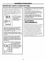
IMPORTANT SAFETY INSTRUCTIONS
This product requires a three-prong grounded outlet.
Tile installer lnust perform a ground cominuily check
oil the power oullet box before beginning the
installation to insure that the outlet box is properly
grounded. If not properly grounded, or if tile oudet
box does not meet eleclrical requiremenls noled
(under ELECTRI(LAL REQUIREMENTS), a qualified
electrician should be eInployed m correct any
deficiencies.
CAUTION: For personal
safety, remove house fuse
or open circuit breaker
before beginning
installation to avoid severe
or fatal shock injury.
CAUTION: For personal safety, the mounting surface
must be capable of supporting the cabinet load, in
addition to the added weight of tlfis 63-85 pound
product, plus additional oven loads of up to 50 pounds
or a total weight of 113-135 pounds.
CAUTION: For personal safety, this product cannot
be installed in cabinet arrangements such as an island or
a peninsula. It must be mounted to BOTH a top cabinet
AND a wall.
NOTE: For easier installation and personal safety, it is
recommended that two people install this product.
IMPORTANT - PLEASE READ CAREFULLY. FOR
PERSONAL SAFETY, THIS APPLIANCE MUST BE
PROPERLY GROUNDED TO AVOID SEVERE OR
FATAL SHOCK.
The power cord of this appliance is equipped with a
three-prong (grounding)
plug which mates with a
standard fluee-prong
(grounding) wall receptacle
to nfinintize the possibility
of electric shock hazard
from this appliance.
Ensure proper
ground exists
before use
You should have the waU receptacle and circuit c_ec&ed
by a qualified electrician to make sure the receptacle is
properly grounded.
Where a standard two-prong wall receptacle is
encountered, it is very important to have it replaced
with a properly grounded three-prong wall receptacle,
installed by a qualified dectridan.
DO NOT, UNDER ANY CIRCUMSTANCES, CUT,
DEFORM OR REMOVE ANY OF THE PRONGS
FROM THE POWER CORD. DO NOT USE WITH
AN EXTENSION CORD.
ELECTRICAL
REQUIREMENTS
Product rating is 120 vohs AC, 60 Hertz, 15 amps and
1.58 kilowatls. This product must be connected m a
supply circuit of 1he proper voltage and frequency.
Wire size must conform to the requirements of the
National Eleclrical Code or the prevailing local
code far this kilowatt rating. The power supply
cord and plug should be brought to a separale
1_ to 20- ampere branch circuit single grounded
omlet. The oudet box should be localed in the
cabinet above the microwave oven. The outlet box
and supply circuit should be installed by a qualified
electrician and contorm m the National Eleclrical
Code or die prevailing local code.
3

Installation Instructions
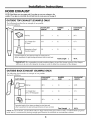
HOOD EXHAUST
NOTE: Read these next two pages only if you plan to vent your exhaust to the
outside. If you plan to recirculate the air back into the room, proceed to page 6.
OUTSIDE TOP EXHAUST (EXAMPLE ONLY)
The followlng chart describes an example of one possible
duclwork installation.
EQUIVALENT NUMBER EQUIVALENT
DUCT PIECES LENGTH x USED = LENGTH
RoofCap 24Ft. x (1) 24Ft.
12Ft.StraightDuct 12Ft. x (1) 12Ft.
(6"Round)
Rectangular-to-Round 5 Ft. x (1) 5 Ft.
TransitionAdaptor*
Equivalentlengthsof ductpiecesarebasedonactualtestsand
reflectrequirementsforgoodventingperformancewith anyventhood.
Total Length = 41 Ft.
* IMPORTANT: If a reclangular-to-round Iransition adaptor is used, Ihe botlom corners of the damper
will have to be cut to fit, using the tin snips, in order to allow flee Inovement of the damper.
OUTSIDE BACK EXHAUST (EXAMPLE ONLY)
The following chart describes an example of one possible
ductwork installation.
EQUIVALENT NUMBER EQUIVALENT
DUCT PIECES LENGTH* x USED = LENGTH
Wall Cap 40 Ft. x (1) 40 Ft.
3 Ft.StraightDuct 3 Ft. x (1) 3 Ft.
3_A"x10"Rectangular)
90° Elbow 10Ft. x (2) 20 Ft.
Equivalentlengthsof ductpiecesarebasedonactualtestsand
reflectrequirementsfor goodventingperformancewithanyvent hood.
Total Length = 63 Ft.
NOTE: For back exhaust, care should be taken to align exhaust wilh space between sluds, or wall should be prepared
at the time it is construoed by leaving enough space between the wall studs m accommodate exhaust.
4

Installation Instructions
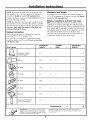
NOTE: lfyou ueed to inslall ducts, uole that the total
duct length of 3¼" x 10" rectaugular or 6" diameter
round duct should not exceed 140 equivalent feet.
Oulside vemilation requires a HOOD EXHAUST DUC'E
Read the followiug carefully.
NOTE: It is imporlant lhat venting be inslalled using
the most direct route and with as few elbows as possible.
This ensures clear veuling of exhaust aud helps prevent
blockages. Also, make sure dampers swing freely and
nothing is blocking the ducts.
Exhaust connection:
The hood exhaust has beeu designed m Illa/e with
a slandard 3_(' x 10" rectangular duct.
If a rouud duct is required, a rectangular-to-round
transition adaptor must be used. Do not use less than
a 6" diameter duct.
Maximum duct length:
For satisfaclory air Inovement, the tolal duct lenglh of
3W' x 10" rectangmlar or 6" diamewr round duct should
not exceed 140 equivalent feet.
Elbows, transitions, wall and roof caps,
etc., present additional resistance to airflow and are
equivalent m a section of straight duct which is longer
than their actual physical size. When calculating Ihe mlal
duct lenglh, add the equivalent lengths of all transitions
and adaptors plus the length of all straight duct sections.
The chart below shows you how m calculate total
equivalent ductwork lenglh using the approximale feet
of equivalent length of some typical ducts.
EQUIVALENT NUMBER EQUIVALENT
DUCT PIECES LENGTH x USED = LENGTH
Rectangular-to-Round 5 Ft. x ( ) Ft.
Transition Adaptor*
'_ Wail Cap 40 Ft. x ( ) Ft.
45° Elbow 5 Ft. x ( ) Ft.
90° Elbow 25 Ft. x ( ) Ft.
45° Elbow 5 Ft. x ( ) Ft.
Roof Cap 24 Ft. x ( ) Ft.
Straight Duct 6" Roundor 1 Ft. x ( ) Ft.
3W'x 10" Rectangular
Total Ductwork = Ft.
* IMPORTANT: Iia rectangqaaPto-round trmlsition t';(luivalc]lt lengths of duct pic{ cs arc based Oll actual tests
ada )tot is used, t|]_" bottoln t'ornels ot the dam )er and refle_ t reqttir_'lll_'nts for good venting pcrformallCC wit]t
will have to be cut to tit, ilsing the tin sni )s, in order any vent hood.
to al]ow ti'cc mov( mcnt of the dmnix'r.
5

Installation Instructions
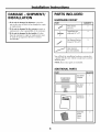
DAMAGE - SHIPMENT/
INSTALLATION
• If the unit is damaged in shipment, return the
unit m file store in which it was bought for repair
or replacement.
• If the unit is damaged by the customer, repair or
replacement is lhe responsibilily of lhe customer.
• If the unit is damaged by the installer (if other
than d_e cuslomer), repair or replacement must
be made by arrangement between cns/omer
and installer.
PARTS INCLUDED
HARDWARE PACKET
PART QUANTITY
Wood Screws 2
(1A:"x 2")
Toggle Bolts {and 4
wing nuts) (_6" x 3")
Self-Aligning Machine 3
Screws (¼"-28 x 3¼")
Nylon Grommet 2
(for metal cabinets)
You will find the inslanatioIl hardware contained in
a packet with the unit. Check Io make sure you have
all these parts.
NOTE: Some extra parts are included.
ADDITIONAL PARTS
PART
Top Cabinet
TOP CABINETTEMPLATE Template
RearWall
Template
REAR
WALL
TEMPLATE
Installation
Instructions
L____
Separately
Packed
Grease
Filters
QUANTITY
1
6

Installation Instructions
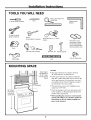
TOOLS YOU WILL NEED
# 1 and #2 Phillips screwdriver
PenciI
Ruleror tapemeasureand
_t edge
Tinsnips(forcutting
damper,if required)
Gloves
Safety goggles
Scissors
(to cut template, if necessary)
Saw (saber,hole or keyhole)
Electric drill with 3AZ',V2"and %"
ddll bits
Filler blocks or scrap
wood pieces, if needed
for top cabinet spacing
(used on recessed bottom
cabinet installations only)
Stud finder e[ Hammer (optional)
I Duct and masking tape
Level
MOUNTING SPACE
66" or More
fremtbe Floor
to the Top of
the Microwave
_J Bottom Edge of
Cabinet Needsto
_be30" or More
from the Cooking
Su_ace
NOTES:
• The space between tile cabinels Inost be
30" wide and free of obs/rucdons.
• If tile space between the cabinets is greater
than 30", a Filler Panel Kit may be used to fill
in the gap between the Inicrowave oven and
the cabinets. Your Owner's Manual contains
the kit mnnber for your model.
• This microwave oven is for installation over
ranges up to 36" wide.
• If you are going to vent your microwave oven
to the outside, see Hood Exhmlst Section for
exhaust duct preparation.
• When installing the microwave oven beneath
smooth, flat cabinets, be careful to follow the
instructions on the top cabinet template for
power cord clearance.
7

Installation Instructions
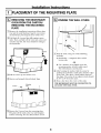
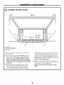
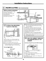
PLACEMENT OF THE MOUNTING PLATE
[-_ REMOVING THE MICROWAVE
OVEN FROM THE CARTON/
REMOVING THE MOUNTING
PLATE
[] Remove the inslMlafion instructions, filters, glass
tray and tile small hardware bag. Do not remove
the S|yrofimm prolecting the front of tile oven.
[]Fold hack all 4 carton flaps fiflly against carton
sides. Then carefhlly roll tile oven and carlon over
onto the lop side. Tile oven should be resting in
the Slyrofbam.
Styrofoam,
_Pull the carton up mid off the oveIl.
[] ReInove mid properly discard plastic bags.
Mounting
Plate
[Remove lhe 2 screws fi'oIll lhe mounting plale.
This plate will be used as dm rear wall template
and for mounting. You may discard these screws.
I-_ FINDING THE WALL STUDS
[] Find the studs, using one of the fbllowing
methods:
A. Stud finder - a Inagnetic dm4ce which
locates nails.
OR
B. Use a hamIner to lap lightly across the
moundng surface lo find a solid sound.
This will indicate a stud location.
[After locating the stud(s), find the cenler by
probing dm wall widl a small nail to find the edges
of dm stud. Then place a mark half,ray bet_veen
the edges. The center of any adjacent studs should
be 16" or 24" fl'om this mark.
[]Draw a line down Ihe center of the studs.
THE MICROWAVE MUST BE CONNECTED TO
AT LEAST ONE WALL STUD.
8

Installation Instructions
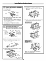
[_ DETERMINING WALL PLATE LOCATION UNDER YOUR CABINET
Plate position - beneath flat bottom
cabinet
/ ' ............................ "../ ' TuuchhNthe CabinetBottom
..o.._ .... jj ".. MountiiNP,ateTabs
At }east30". upto 36"
Plate position - beneath framed recessed
cabinet bottom
MountingHateTabs
Touchingthe Sack
Frame
III
30" to Cuoktop
Plate position - beneath recessed bottom
cabinet with front overhang
MountingHatewith
TabsBetowCabinet
Bottomthe Same
Distanceasthe Front
OverhangDepth
I It
I II
30"to Cooktop
Yotlr cabinels Illay have decorative trim lbat iIllerl_eres
with the microwave installation. Remove the decorative
trim m install tile microwave properly and m make it
level.
THE MICROWAVE MUST BE LEVEL.
Use a level to make sure the cabinet bottom is level.
If tile cabinels have a front overhang only, wilb no
back or side frame, inslall the mourning plate down
the same distance as tile front overhang depth. This
will keep the microwave level.
_ Mea_sure the inside depth of the fi_ont overhang.
[] Draw a horizontal line on die back wall an equal
distance below the cabinet bottoIn as the inside
depth of the fi_Ollt overhang.
[] For lhis type of installation wilh front overhang only,
align lhe mounting labs with lhis horizontal line, not
touching the cabinet bottom a_ described in Step D.
9

Installation Instructions
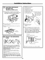
[] ALIGNING THE WALL PLATE
CAUTION: Wear gloves
to avoid cutting fingers on
sharp edges.
oOo oOoOoOoO OoO, iOoOoOoOo OoOoOoOo o I
\\
Area E Hole D
[]Draw a vertical line oil |he wall at tile cenler of tile
30" wide space.
[] Use lhe Inounfing plate as the template for tile rear
wall. Place the mounting plale on tile wall, Inaking
sore that tile tabs are touching the bottom of the
cabinet or the level llne drawn in Step C for cabinets
with front overlmng. Line up the notch and centerline
on the bottom of the mounting plate to the centerline
on the wall.
[] While holding Ihe mounting plale with one hand,
draw circles on lhe wall at holes A, B, C and D
(see illustralion above/actual plate, marked with
arrows). Four holes must be used for mounting.
[]
NOTE: Holes C and D are inside area E. If neilher
(] nor D is in a slud, find a stud somewhere in area E
and draw a fifth circle m line up wilh the stud. It is
iInporlant lo use at least one wood screw lnouIlled
firmly in a stud lo support lhe weight of the microwave.
Set the mounting plate aside.
Drill holes on the circles. If there is a stud, drill a :_"
hole fbr wood screws. For holes that don't line up with
a stud, drill a %" hole for toggle bolls.
NOTE: DO NOT MOUNT THE PLATE AT THIS
TIME.
10

Installation Instructions
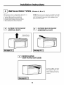
INSTALLATION TYPES (Choose A, B or C)
This Inicrowave oven is designed for adaptation to
the following three types of ventilation:
A. Outside Top Exhaust (Vertical Duct)
B. Outside Back Exhaust (Horizontal Duct)
C. Recirculatlng (Non-Vented Ductless)
NOTE: This microwave is shipped asseInbled for Oulside
"Ibp Exhmlst (except for non-vented models). Select the
type of ventilation required for your installation and
proceed to that seclion.
[-_ OUTSIDE TOP EXHAUST
(VERTICAL DUCT)
_-] OUTSIDE BACK EXHAUST
(HORIZONTAL DUCT)
Adaptorin Racefor
j OutsNeTapExhaust
/
RECIRCULATING
(NON-VENTED DUCTLESS)
A Charcoal Filter Accessory
Kit is required f;.)r the Ilon-
vetoed exhaust. (See your
Owner's Manual for tile kit
number.)
11

Installation Instructions
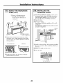
OUTSIDE TOP EXHAUST (Vertical Duct)
INSTALLATION OVERVIEW
A1. Atlach Moundng Plate to Wall
A2. Prepare "Ibp Cabinet
A3. Check Damper Operation
A4. Mount Microwave Oven
AS. Adiost Exhaust Adaptor
A6. Connect Ductwork
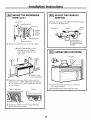
I-_ ATTACH THE MOUNTING
PLATE TO THE WALL
Atlach the plate m the wall using toggle bolts.
At least one wood screw l](ll_lStbe used to attach
tile plate to a wall stud.
[] Remove tile loggle wings ti'Olll tile bohs.
[] Insert the bolts into tile moundng plate
through tile holes designated to go into drywall
and reattach tile loggle wings to :_A"onlo each bolt.
To use toggle bolts:
Spacingfor Toggles
MoreThanWall
_l_Ttlickness
IToggleWings
Mounting IIII I /Toqqle II I'1
PIate,dlLl_ II Ik
111:[2 ,, ,,
Bolt[nd
[] Place the mounting plate against the wall and
insert tile loggle wings into the holes in the wall
to II_lo/lnt tile plate.
NOTE: Before tightening toggle bolts and wood
s(rew, inake sllre tile tabs oil tile inolln[iIlg pla_e
louch tile bottom of the cabinet when pushed
flush a_ainst tile wall and that tile plate is properly
centered under the cabinet.
CAUTION: Be careful to avoid pinching fingers
between the back of die mounting plate and the wall.
_ Tighten all bolts. Pull tile plate away from the wall
to help tighten tile bohs.
12

Installation Instructions
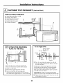
USE TOP CABINET TEMPLATE
FOR PREPARATION OF TOP
CABINET
You need to drill holes ff_r the top support screws, a
hole large enough for ltle power cord to fil lhrough,
and a cutout large enough for the exhaust adaptor.
• Read tim instructions Oil tile TOP CABINET
TEMPLATE.
• "Pape it underneath die lop cabinet.
• Drill the holes, fbllowing the instructions Oil tile
TOP CABINET TEMPLATE.
CAUTION: Wear safety goggles when drilling holes
in tile cabinet bottom.
CHECK FOR PROPER
DAMPER OPERATION
Newer Hate
Exhaust Adaptor
{absentonmodelsshipped
for rec#culationexhaust)
• Place the microwave in ils upright posilion, with tile
top of tile unit facing up.
• This microwave oven may be shipped assembled for
top exhaust (adaptor installed) or for recircolalion
exhaust (adaptor absent).
• Make sure tape securing damper is removed and
damper pivots easily before mounting microwave.
• You will need m make adjnstments lo assure proper
alignInent with your house exhaust duct after the
Inicrowave is installed.
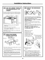
I-_ MOUNT THE MICROWAVE
OVEN
FOR EASIER INSTALLATION AND PERSONAL
SAFE'IN, WE RECOMMEND THAT TWO PEOPLE
INSTALL THIS MICROWAVE OVEN.
IMPORTANT: Do not grip or use handle
during installation.
NOTE: If your cabinet is metal, ose tile nylon
grommet aroond the power cord hole to prevent
cutting of the cord.
NOTE: We recommend nsing filler blocks if the
cabinet front hangs below the cabinet bottom shell
IMPORTANT: If filler blocks are
not used, case damage may occur from
overtightening screws.
NOTE: When mounting
tile microwave ()veil,
thread power cord
through hole in bottom of
mp cabinet. Keep it fight
throughout Stops 1-3. Do
not pinch cord or lift
oven by pulling cord.
_Lifl tilt it
Inicrowave,
forward, and hook
slots at hack bottom
edge onto four lower
labs of inouIlliIlg
/ \
_ Rotate ]_i'Ollt of oven \\\
\
up against cabinet \_5._
bottom.
[] Insert a self:aligning screw through top center
cabinet hole. Temporarily secure tile oven by
turning tile screw at least two full turns afler tile
threads have engaged. (It will be complelely
lightened lalen) Be sure to keep power cord
tight. Be careful not m pinch the cord, especially
when mounting flush to bottom of cabinet.
13

Installation Instructions
MOUNT THE MICROWAVE
OVEN (cont.)
CabinetFront
"_A CabinetBottomShetf
_"_LIL / FillerBlock
[l'i / Ill.Ill[ mill | toDepth
I!'_,,,IlHIIF!Ilil_ o,Cobinet
_\_, "_ __t_Rooess
Microwave OvenTop
[_ Attach the microwave uven to tile top cabinet.
[] Insert 2 self:aligning screws
through outer top cabinet
holes. "I_rn two fhll turns on
each s(-rew.
[] Tighten center
screw completely.
_ Tighten the outer two screws to file lop of file
microwave oven. (While tightening screws, hold
tile microwave oven in place against the wall and
tile 1up cabinet.)
1400and 1600 Series 1800 Series
[] lnslall grease fillers. See the Owner's Mmmal
packed with the microwave.
ADJUST THE EXHAUST
ADAPTOR
Open the top cabinet and adiust tile exhaust adaptor
tu conIleCt tu the huuse duct.
Backof
BiowerRate Damper
Microwave
\ \
Side-to-Side Adjustment,
Slide the Exhaust Adapter
as Needed
I-_ CONNECTING DUCTWORK
House Duct
_ ExleIld tile house duct duwn to connect tu
the exhausl adaptur.
[] Seal exhaust duct joints using duct tape.
14

Installation Instructions
OUTSIDE BACK EXHAUST (Horizontal Duct)
INSTALLATION OVERVIEW
B1. Prepare Rear Wall
B2. Remove Exhaust Adaptor
B3. Atlach Mmmting Pla/e m Wall
B4. Prepare "Ibp Cabinet
B5. Adjust Blower
B6. Mount tile Microwave Oven
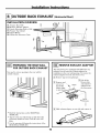
[_ PREPARING THE REAR WALL
FOR OUTSIDE BACK EXHAUST
You need to cut an opening in tile rear wall for
outside exhaust.
• Read the inslructions Oil tile REAR _'kLL
TEMPLATE.
• "lZape it lo tile rear wall, lining up wilh the holes
previously drilled for holes A and B in the wall
plate.
• Cut the opening, fbllowiiag tile instructions of the
REAR WALL TEMPLATE.
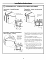
[-_ REMOVE EXHAUST ADAPTOR
] Remove and
save screw
that holds
blower plale
to microwave.
This Inicrowave oven is shipped assembled for top
exhausl. You will need the exhaust adaptor for
installalion in the rear wall opening. "Ib reInove tile
exhausl adaptor from Ihe microwave oven:
] ReInove tape securing damper.
_Liff off the
blower plate
and attached
Damper adaplor fi*OIll
•tile lnicrowave.
/
_ Slide exhaust adaptor to one side and remove it.
15

Installation Instructions
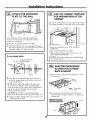
I-_ ATTACH THE MOUNTING
PLATE TO THE WALL
Atlach the plale lo lbe wall using toggle bolls.
At leaet one wood screw IIlUSt be used to attach
tile plate to a wall slud.
[]Remove llle toggle wings fYoIn tile bolts.
[]Insert tile bolts into tile mounting pla/e through
tile holes designaled to go into drywall and reattach
tile toggle wings m '-"/4"onto each bolt.
To use toggle bolts:
Mounting
Plate
Spacingfor TogglesMore
_-_ ThanWallThickness
ToggleWings
BoltEnd
[] Place the Inounting plate against the wall and
insert lhe toggle wings into the holes in the wall
to mount the plate.
NOTE: Before tighlening toggle bolts and wood
screw, make sure tile labs on lbe mounting plale
much tile bottom of the cabinet when pushed flush
against die wall and that lbe plate is properly
cen/ered under tile cabinet.
CAUTION: Be carefial to avoid pinching fingers
between die back of lhe mounting plate and die wall.
[] Tighten all bolts. Pull 1lie plme away from the wall
m help lighten the bolts.
I-_ USE TOP CABINET TEMPLATE
FOR PREPARATION OF TOP
CABINET
You need to drill holes for file top support screws mid
a hole large enough ff_r the power cord to fit through.
• Read the instructions on the TOP CABINET
TEMPLATE.
• "Pape it underneath the top cabinet.
• Drill the boles, tbllowing the instructions on the
TOP CABINET TEMPLATE.
CAUTION: Wear safety goggles when drilling holes
in the cabinet bottom.
[_ ADAPTING MICROWAVE
BLOWER FOR OUTSIDE
BACK EXHAUST
[] ReIIlove arid that holds blower Iilotor
save screw
to Inicrowave.
BlowerMotor
Backof
Microwave
-_ BlowerMotor
- _ Sc[ew
[] Carefiflly pull out the blower unit. Tile wires
will extend fhr enough to allow you to ad}ust tile
blower unit.
_End B
16

Installation Instructions
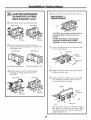
ADAPTING MICROWAVE
BLOWER FOR OUTSIDE
BACK EXHAUST (cont.)
_] Rolate blower unit counterclockwise 180 °.
Before Rotation After Rotation
Microwave Microwave
[]Gently tile wires fi'oIll lhe
reIllove
grooves.
Reroute the wires through grooves on other side
of die blower unit.
Before Rerouting After Rerouting
Wires Routed Through Right Side Wires Routed Through Left Side
_] Roll the blower unit 90 ° lhat fan blade
so
openings are facing out tile back of the
lnicrowave.
Before Rolling After Rolling
Backof
Microwave
Microwave
[] Place tile blower unit back into the opening.
End
CAUTION: Do not pull or stretch the blower
unit wiring. Make sure the wires are not
pinched.
NOTE: The blower unit exhaust
openings should match exhaust
openings on rear of microwave oven.
] Secure Ihe blower unit to the Inicrowave with
the screw from Step 1.
BlowerPIate
I Backof
Microwave
BlowerMotor
Screw
[] Replace the blower plale in the same position
as before with the screw.
_ Altach dm exhaust adaplor to the rear of the
oven by sliding il inlo the guides at the top
center of the hack of the oven.
Adaptor
\
Backof
Microwave
/
Guide
Guide
- LockingTabs
Push in securely undl it is in dm lower locking
tabs. Take care to assure that the damper hinge
is installed so that it is at the lop and that the
damper swings fi'eely.
17

Installation Instructions
MOUNT THE MICROWAVE
OVEN
FOR EASIER INSTALLATION AND PERSONAL
SAFETY, WE RECOMMEND THAI" TWO PEOPLE
INSTALL THIS MICROWAVE OVEN.
IMPORTANT: Do not grip or use handle
during installation.
NOTE: If your cabinet is melM, use the nylon
grommet around the power cord hole m prevent
cutting of the cord.
NOTE: We recommend using filler blocks if the
cabinet fi'ont hangs below the cabinet bottom shel£
IMPORTANT: If filler blocks are
not used, case damage may occm" from
overtightening screws.
NOTE: When moondng
the IUi(Towave oveIl_
thread power cord
through hole in bottom of
top cabinet. Keep it tight
throughout Steps 1-3. Do
not pinch cord or lift
oven by pulling cord. "'_l
[] Lift microwave, dlt it
ff)rward, and hook
slots at back bottom
edge oIlto four lower
labs of nlOllIl/ing
_ Rolale [i'onl of oveIl
tip against cabinet
bottom.
_lnsert a self:aligning screw lhrough mp center
cabinet hole. TeInporarily secure the oven by
ttlrning the screw at least two full turns after the
threads have engaged. (It will be completely
lighlened later.) Be sure to keep power cord
tight. Be careful not to pinch the cord, especially
when mounting flush to bottom of cabinet.
CabinetFront
_//abinet,.. -----_°tt°m SheI
_Qi_! _ Self-Alignin9Screw
MicrowaveOvenTop
_ Attach tile microwave oven to tile top cabinet.
Filler Block
--Equivalent
to Depth
of Cabinet
Recess
[] Insert 2 self:aligning screws
dlrough ouler top cabinet
holes. Turn two full tun_s on
each screw.
I
[] Tighlen center
screw completely.
[] Tighlen dm ouler two screws to the top of tile
Inicrowave oven. (While tightening screws, hold
the Inicrowave oven in place against the wall and
the top cabinet.
1400 and 1600 Series 1800 Series
[] lnslall grease fillers. See dm Owner's Manual
packed with tile microwave.
18

Installation Instructions
RECIRCULATING (Non-Vented Ductless)
INSTALLATION OVERVIEW
C1. Attach Mounting Plale to Wall
C2. Prepare Top Cabinet
C3. Check Microwave Assembly
CA. Adjust Blower
C5. Mount lbe Microwave Oven
C6. Install Charcoal Filter
I-_ ATTACH THE MOUNTING
PLATE TO THE WALL
\
Altach the plale to tile wall using toggle bolts.
A1 least oIle wood screw IlltlSt be used to attach
die plate lo a wall slud.
[]Remove tile toggle wings from tile bolls.
[] lnserl die bolls inlo tile inounlJng plate lhrough
lbe holes designated Io go into drywall and
reattach the loggle wings lo _(' omo each bolt.
To use toggle bolts:
Spacingfor Toggles
MoreThanWall
_._Thickness
lToggleWings
Mounting i / Toggle
P'ete lllll. 'B°'tII
IIV ,_Wall II b I
BoltEnd
_ Place the mounting plate against the wall and
insert lbe loggle wings imo the holes ill the wall
to mount lbe plale.
NOTE: Befbre dghlening Ioggle bolls and wood
screw, make s/lre lille labs on lille IllOllntiIlg plale
louch tile bottoln of the cabinet when pushed flush
against lbe wall and that lbe plate is properly
centered under the cabinet.
CAUTION: Be carefill to avoid pinching fingers
between the back of lbe mounting plale and the wall.
[] Tighten all bolls. Pull tile plate away from the wall
to help tighten tile bohs.
USE TOP CABINET TEMPLATE
FOR PREPARATION OF TOP
CABINET
You need to drill holes for lbe lop supporl screws and
a hole large enough fi_r the power cord to fit dlrough.
L
• Read the instructions oil the TOP CABINET
TEMPLATE.
• Tape it underneath the top cabinet.
• Drill the holes, following the instructions oil the
TOP CABINET TEMPLATE.
CAUTION: Wear safety goggles when drilling holes
in die cabinet bottom.
19

Installation Instructions
CHECK MICROWAVE ASSEMBLY
Exhausl Adaptor (absent
on models shipped fior
recirculation exhaust) \
• Place tile microwave in ils upright position, with the
top of the unit fbcing tip.
• The microwave oven m_y be shipped assembled fbr
top exhaust (adaptor instMled) or for recirculafion
exhaust (adaptor absent).
• lfthe microwave was shipped for recirculation
exhaust, skip lo C5. If shipped for lop exhaust,
proceed with C4.
ADAPTING MICROWAVE
BLOWER FOR RECIRCULATION
[] Remove [] Lift off the
and save blower plate
screw dmt and attached
holds blower adaplor from
plate to the microwave.
lnic rowave.
_Microwave
-. 7"
[] Slide exhaust adaptor m one side and remove it.
NOTE: The exhaust adaptor wilh damper is not
needed for recirculating models. Yon may want m
save them for possible future use.
_ Remove and the that holds the blower
save screw
inotor tO ltle microwave.
BIowerPlate
_, Careflfllypull out the blower unit. The wires,
will extend fbr enough to allow you to ad}ust the
blower uIfit.
[] Roll tile blower unit 90 ° so ltlat fan blade opeIfings
are fhcing toward the front of the Inicrowave.
R0tl
NOTE: Make sure wires reInain routed in the
grooves of the motor fl*ame.
2O
Page is loading ...
Page is loading ...
Page is loading ...
Page is loading ...
-
 1
1
-
 2
2
-
 3
3
-
 4
4
-
 5
5
-
 6
6
-
 7
7
-
 8
8
-
 9
9
-
 10
10
-
 11
11
-
 12
12
-
 13
13
-
 14
14
-
 15
15
-
 16
16
-
 17
17
-
 18
18
-
 19
19
-
 20
20
-
 21
21
-
 22
22
-
 23
23
-
 24
24


Ask a question and I''ll find the answer in the document
Finding information in a document is now easier with AI
Related papers
-
GE JVM1665 User manual
-
GE JVM2052 User manual
-
GE JVM1665SN2SS Owner's manual
-
-
GE JVM3670WF09 Installation guide
-
-
-
-
-
Frigidaire PVM1870DM2WW Installation guide
Other documents
-
 Mr. Goodbar S400 BD 26 Installation guide
-
GE Profile PVM9179DKBB Top Cabinet Template
-
Frigidaire FMT148GPB1 Installation guide
-
Samsung MC17T8000CG Installation guide
-
Philips BTB2462/05 Quick Setup Guide
-
Summit MHOTR243SS Installation guide
-
Haier HMV1652 Installation Instructions Manual
-
Conair 136W Datasheet
-
Kenmore 83529 Installation guide
-
SPT 10108 Installation guide
