Page is loading ...

2/01/2002 (Original Publication)
(Updated 10/14/2020)
OPERATOR’S
MANUAL
Model 750, 751, 754, 774,
791, and 794 Soft Serve Freezer
Original Operating Instructions
028754-M

Complete this page for quick reference when service is required:
Taylor distributor:___________________________________________________________
Address: _________________________________________________________________
Phone: __________________________________________________________________
Service:__________________________________________________________________
Parts: ___________________________________________________________________
Date of installation: _________________________________________________________
Information found on the data label:
Model Number: ____________________________________________________________
Serial Number: ____________________________________________________________
Electrical Specs: Voltage__________________ Cycle__________
Phase__________________________________
Maximum Fuse Size: ______________________________________________________A
Minimum Wire Ampacity: ___________________________________________________A
Note: Continuing research results in steady improvements; therefore, information in this manual is subject
to change without notice.
Only instructions originating from the factory or its authorized translation representative(s) are considered to
be the original set of instructions.
© 2002 Taylor Company
028754-M
Any unauthorized reproduction, disclosure, or distribution of copies by any person of any portion of this work may be
a violation of Copyright Law of the United States of America and other countries, could result in the awarding of Stat-
utory Damages of up to $250,000 (17 USC 504) for infringement, and may result in further civil and criminal penal-
ties.
All rights reserved.
Taylor Company
750 N. Blackhawk Blvd.
Rockton, IL 61072

Table of Contents
028754-M i
Section 1: To the Installer
Installer Safety ...................................................................................................1-1
Site Preparation .................................................................................................1-1
Air-Cooled Machines..........................................................................................1-1
Water Connections.............................................................................................1-2
Electrical Connections........................................................................................1-2
Beater Rotation..................................................................................................1-3
Refrigerant .........................................................................................................1-3
Section 2: To the Operator
Compressor Warranty Disclaimer......................................................................2-2
Section 3: Safety
Section 4: Operator Parts Identification
Model 750 ..........................................................................................................4-1
Model 751 ..........................................................................................................4-2
Model 754 ..........................................................................................................4-3
Model 774 ..........................................................................................................4-4
Model 774 Topping Pump (053794-) .................................................................4-5
Model 791 ..........................................................................................................4-6
Model 794 ..........................................................................................................4-7
Models 750 and 751 Single-Spout Door and Beater Assembly.........................4-8
Models 754, 774 and 794 Three-Spout Door and Beater Assembly..................4-9
Model 791 Three-Spout Door and Beater Assembly .......................................4-10
Accessories......................................................................................................4-11
Section 5: User Interface
750/751..............................................................................................................5-1
754/774/791/794................................................................................................5-1
Symbol Definitions .............................................................................................5-2
Power Switch .....................................................................................................5-2
MIX LOW Indicator Light....................................................................................5-2

ii 028754-M
MIX Refrigeration Button....................................................................................5-2
STANDBY Button...............................................................................................5-2
WASH Button.....................................................................................................5-2
AUTO Button......................................................................................................5-3
RESET Button....................................................................................................5-3
Air Tube..............................................................................................................5-3
Adjustable Draw Handle.....................................................................................5-4
Section 6: Operating Procedures
Prior to Setup (Model 774).................................................................................6-1
Assembly............................................................................................................6-1
Sanitizing............................................................................................................6-6
Priming...............................................................................................................6-8
Closing Procedure..............................................................................................6-9
Draining Product from the Freezing Cylinder.....................................................6-9
Rinsing ...............................................................................................................6-9
Cleaning.............................................................................................................6-9
Disassembly.......................................................................................................6-9
Manual Brush-Cleaning....................................................................................6-10
Section 7: Operator’s Checklist
During Cleaning and Sanitizing..........................................................................7-1
Troubleshooting Bacterial Count........................................................................7-1
Regular Maintenance Checks............................................................................7-1
Winter Storage ...................................................................................................7-2
Section 8: Troubleshooting Guide
Section 9: Parts Replacement Schedule
Maintenance Intervals........................................................................................9-1
Section 10: Limited Warranty on Equipment
Section 11: Limited Warranty on Parts

Section 1
1-1
Models 750, 751, 754, 774, 791, and 794
To the Installer
1
To the Installer
The following information has been included in the
manual as safety and regulatory guidelines. For complete
installation instructions, please see the Operator’s
Checklist.
Installer Safety
IMPORTANT! In all areas of the world,
machines should be installed in accordance with existing
local codes. Please contact your local authorities if you
have any questions.
Care should be taken to ensure that all basic safety
practices are followed during the installation and
servicing activities related to the installation and service
of Taylor
®
machines.
• Only Taylor service personnel should perform
installation, maintenance, and repairs on Taylor
machines.
• Authorized service personnel should consult
OSHA Standard 29CFRI910.147 or the
applicable code of the local area for industry
standards on lockout/tagout procedures before
beginning any installation or repairs.
• Authorized service personnel must ensure that
the proper personal protective equipment (PPE)
is available and worn when required during
installation and service.
• Authorized service personnel must remove all
metal jewelry, rings, and watches before
working on electrical equipment.
DANGER! The main power supply(s) to the
machine must be disconnected prior to performing any
installation, maintenance, or repairs. For Cord-
Connected Machines: Only authorized Taylor service
technicians or licensed electricians may install a plug or
replacement cord on the machine. Failure to follow this
instruction may result in personal injury or death from
electrical shock or hazardous moving parts, as well as
poor performance or damage to the machine.
Note: All repairs must be performed by a Taylor service
technician.
WARNING! This machine has many sharp
edges that can cause severe injuries.
Site Preparation
Review the area the machine is to be installed in before
uncrating the machine, making sure that all possible
hazards regarding the user or equipment have been
addressed.
Air-Cooled Machines
Do not obstruct air intake and discharge openings:
Counter Model: 6 in. (152 mm) minimum airspace on
both sides and 0 in. (0.0 mm) on the rear.
Console Models: 3 in. (76 mm) minimum airspace on all
sides.
This will allow for adequate airflow across the
condenser(s). Failure to allow adequate clearance can
reduce the refrigeration capacity of the freezer and
possibly cause permanent damage to the compressor.
For Indoor Use Only: This machine is designed to
operate indoors, under normal ambient temperatures of
70°F to 75°F (21°C to 24°C). The freezer has
successfully performed in high ambient temperatures of
104°F (40°C) at reduced capacities.
WARNING! This machine must NOT be
installed in an area where a water jet or hose can be
used. NEVER use a water jet or hose to rinse or clean
the machine. Failure to follow this instruction may result
in electrocution.
CAUTION! This machine must be installed on
a level surface to avoid the hazard of tipping. Extreme
care should be taken in moving this machine for any
reason. Two or more persons are required to safely move
this machine. Failure to comply may result in personal

1-2
TO THE INSTALLER
Models 750, 751, 754, 774, 791, and 794
To the Installer
1
injury or damage to the machine.
The authorized installer should inspect the machine and
promptly report any damage to the local authorized
Taylor distributor.
This machine is made using USA sizes of hardware. All
metric conversions are approximate and vary in size.
Water Connections
(Water-Cooled Machines Only)
An adequate cold water supply must be provided with a
hand shutoff valve. On the underside rear of the base
pan, two 3/8 in. IPS (for single-head units) or two 1/2 in.
IPS (for double-head units) water connections for inlet
and outlet have been provided for easy hookup.
Permanently connect the machine using 1/2 in. (12.7
mm) inside diameter water lines. (Flexible lines are
recommended, if local codes permit.) Depending on local
water conditions, it may be advisable to install a water
strainer to prevent foreign substances from clogging the
automatic water valve. There will be only one water-in
and one water-out connection for both single-head and
double-head units. Do not install a hand shutoff valve on
the water-out line! Water should always flow in this
order: first, through the automatic water valve; second,
through the condenser; and third, through the outlet
fitting to an open trap drain.
IMPORTANT! A backflow prevention device is
required on the incoming water connection side. Please
see the applicable national, state, and local codes for
determining the proper configuration. Water pressure to
the unit must not exceed 150 psi (1034 kPa).
Electrical Connections
In the United States, this machine is intended to be
installed in accordance with the National Electrical Code
(NEC) ANSI/NFPA 70-1987. The purpose of the NEC
code is the practical safeguarding of persons and
property from hazards arising from the use of electricity.
This code contains provisions considered necessary for
safety. In all other areas of the world, machines should
be installed in accordance with the existing local codes.
Please contact your local authorities.
Each machine requires one power supply for each data
label on the machine. Check the data label(s) on the
freezer for branch circuit overcurrent protection or fuse,
circuit ampacity, and other electrical specifications. See
the wiring diagram provided inside the electrical box for
proper power connections.
WARNING! This machine must be properly
grounded. Failure to do so can result in severe personal
injury from electrical shock.
WARNING! DO NOT operate this freezer with
fuses larger than specified on the machine data label.
Failure to follow this instruction may result in
electrocution or damage to the machine.
IMPORTANT! An equipotential grounding lug is
provided with this machine. Some countries require the
grounding lug to be properly attached to the rear of the
frame by the authorized installer. The installation location
is marked by the equipotential bonding symbol (5021 of
IEC 60417-1) on both the removable panel and the
machine's frame.
IMPORTANT!
• Stationary machines which are not equipped
with a power cord and a plug or another device
to disconnect the machine from the power
source must have an all-pole disconnecting
FOLLOW YOUR LOCAL ELECTRICAL CODES.

TO THE INSTALLER
1-3
Models 750, 751, 754, 774, 791, and 794
To the Installer
1
device with a contact gap of at least 0.125 in.
(3 mm) in the external installation.
• Machines that are permanently connected to
fixed wiring and for which leakage currents may
exceed 10 mA, particularly when disconnected
or not used for long periods, or during initial
installation, shall have protective devices to
protect against the leakage of current, such as a
GFI, installed by authorized personnel to local
codes.
• Supply cords used with this machine shall be
oil-resistant, sheathed flexible cable not lighter
than ordinary polychloroprene or other
equivalent synthetic elastomer-sheathed cord
(code designation 60245 IEC 57) installed with
the proper cord anchorage to relieve conductors
from strain, including twisting, at the terminals
and protect the insulation of the conductors from
abrasion.
If the supply cord is damaged, it must be replaced by a
Taylor service technician to avoid a hazard. Secure the
supply cord ground lead to the machine in a location
where if the cord is pulled the main power leads will
become taut before the ground lead can break loose.
Beater Rotation
NOTICE! Beater rotation must be clockwise as
viewed looking into the freezing cylinder.
To correct the rotation on a three-phase machine,
interchange any two incoming power supply lines at the
freezer main terminal block only. To correct rotation on a
single-phase machine, exchange leads inside the beater
motor. (Follow the diagram printed on the motor.)
Electrical connections are made directly to the terminal
block provided in the main control box, located behind
the service panel.
It is recommended that beater rotation adjustment be
performed by a Taylor service technician.
Refrigerant
CAUTION! This machine contains fluorinated
greenhouse gases (F-Gas) to provide refrigeration using
a hermetically sealed circuit or within foam insulation.
This machine’s type of gas, quantity, Global Warming
Potential (GWP), and CO
2
tonnes equivalent information
is recorded on the machine’s data label. The refrigerant
used is generally considered nontoxic and
nonflammable. However any gas under pressure is
potentially hazardous and must be handled with caution.
NEVER fill any refrigerant cylinder completely with liquid.
Filling the cylinder approximately 80% will allow for
normal expansion.
CAUTION! Use only approved refrigerant
listed on the machine's data label or authorized through a
manufacturer's technical bulletin. The use of any other
refrigerant may expose users and operators to
unexpected safety hazards.
WARNING! Refrigerant liquid sprayed onto the
skin may cause serious damage to tissue. Keep eyes
and skin protected. If refrigerant burns should occur,
flush the area immediately with cold water. If burns are
severe, apply ice packs and contact a physician
immediately.
NOTICE! Taylor reminds technicians to be
aware of and in compliance with local government laws
regarding refrigerant recovery, recycling, and reclaiming
systems. For information regarding applicable local laws,
please contact your local authorized Taylor distributor.
IMPORTANT! Refrigerants and their
associated lubricants may be extremely moisture
absorbent. When opening a refrigeration system, the
maximum time the system is open must not exceed 15
minutes. Cap all open tubing to prevent humid air or
water from being absorbed by the oil.

1-4
TO THE INSTALLER
Models 750, 751, 754, 774, 791, and 794
To the Installer
1

Section 2
2-1
Models 750, 751, 754, 774, 791, and 794
To the Operator
2
To the Operator
The freezer you have purchased has been carefully
engineered and manufactured to give you dependable
operation. The Taylor soft serve models covered in this
manual are the following: 750, 751, 754, 774, 791, and
794.
These machines, when properly operated and cared for,
will produce a consistent quality product. Like all
mechanical products, they will require cleaning and
maintenance. A minimum amount of care and attention is
necessary if the operating procedures outlined in this
manual are followed closely.
IMPORTANT! This manual should be read
before operating or performing any maintenance on the
machine.
Your Taylor machine will NOT compensate for and/or
correct any errors made during setup or filling operations.
Thus, the initial assembly, setup, and priming procedures
are of extreme importance. It is strongly recommended
that all personnel responsible for the machine's
operation, including assembly and disassembly, go
through these procedures together to be properly trained
and to make sure that all personnel understand their role
in using and maintaining the machine.
If you require technical assistance, please contact your
local authorized Taylor distributor.
Note: Your Taylor warranty is valid only if the parts are
authorized Taylor parts purchased from the local
authorized Taylor distributor, and only if all required
service work is provided by a Taylor service technician.
Taylor reserves the right to deny warranty claims on
machines or parts if unapproved parts or incorrect
refrigerant were installed in the machine, system
modifications were performed beyond factory
recommendations, or it is determined that the failure was
caused by abuse, misuse, neglect, or failure to follow all
operating instructions. For full details of your Taylor
warranty, please see the Limited Warranty section in this
manual.
Note: Constant research results in steady
improvements; therefore, information in this manual is
subject to change without notice.
IMPORTANT! If the crossed-out wheeled bin
symbol is affixed to this machine, it signifies that this
machine is compliant with the EU directives as well as
other similar end-of-life legislation in effect after August
13, 2005. Therefore, it must be collected separately after
its use is completed and cannot be disposed as unsorted
municipal waste.
The user is responsible for delivering the machine to the
appropriate collection facility as specified by your local
code.
For additional information regarding applicable local
disposal laws, please contact the municipal waste facility
and/or local authorized Taylor distributor.
For additional information regarding applicable local
laws, please contact the municipal facility and/or local
distributor.

2-2
TO THE OPERATOR
Models 750, 751, 754, 774, 791, and 794
To the Operator
2
Compressor Warranty Disclaimer
The refrigeration compressor(s) on this machine are
warranted for the term stated in the Limited Warranty
section in this manual. However, due to the Montreal
Protocol and the U.S. Clean Air Act Amendments of
1990, many new refrigerants are being tested and
developed, thus seeking their way into the service
industry. Some of these new refrigerants are being
advertised as drop-in replacements for numerous
applications. It should be noted that in the event of
ordinary service to this machine's refrigeration system,
only the refrigerant specified on the affixed data label
should be used. The unauthorized use of alternate
refrigerants will void your Taylor compressor warranty. It
is the machine owner's responsibility to make this fact
known to any technician he/she employs.
It should also be noted that Taylor does not warrant the
refrigerant used in its equipment. For example, if the
refrigerant is lost during the course of ordinary service to
this machine, Taylor has no obligation to either supply or
provide its replacement either at billable or unbillable
terms. Taylor does have the obligation to recommend a
suitable replacement if the original refrigerant is banned,
obsoleted, or no longer available during the 5-year
warranty of the compressor.
The Taylor Company will continue to monitor the industry
and test new alternates as they are being developed.
Should a new alternate prove, through our testing, that it
would be accepted as a drop-in replacement, the above
disclaimer would become null and void. To find out the
current status of an alternate refrigerant as it relates to
your compressor warranty, call the local Taylor distributor
or the Taylor factory. Be prepared to provide the
model/serial number of the machine in question.

Section 3
3-1
Models 750, 751, 754, 774, 791, and 794
Safety
3
Safety
We at the Taylor Company are concerned about the
safety of the operator when he or she comes into contact
with the freezer and its parts. Taylor has gone to extreme
efforts to design and manufacture built-in safety features
to protect both you and the service technician. As an
example, warning labels have been attached to the
freezer to further point out safety precautions to the
operator.
IMPORTANT! This machine is to be used only
by trained personnel. It is not intended for use, cleaning,
or maintenance by children or people with reduced
physical, sensory, or mental capabilities or lack of
experience and knowledge, unless given supervision or
instruction concerning the use of the machine by a
person responsible for their safety. Children should be
supervised to ensure that they do not play with the
machine.
WARNING! This machine must NOT be
installed in an area where a water jet or hose can be
used. NEVER use a water jet or hose to rinse or clean
the machine. Failure to follow this instruction may result
in electrocution.
IMPORTANT! An equipotential grounding lug is
provided with this machine. Some countries require the
grounding lug to be properly attached to the rear of the
frame by the authorized installer. The installation location
is marked by the equipotential bonding symbol (5021 of
IEC 60417-1) on both the removable panel and the
machine's frame.
WARNING! Avoid injury.
• DO NOT operate the machine unless it is
properly grounded.
• DO NOT operate machine with fuses larger than
specified on the data label.
• All repairs must be performed by a Taylor
service technician.
• The main power supplies to the machine must
be disconnected prior to performing repairs.
• For Cord-Connected Machines: Only Taylor
service technicians or licensed electricians may
install a plug or replacement cord on the
machine.
• Stationary machine that are not equipped with a
power cord and a plug or another device to
disconnect the machine from the power source
must have an all-pole disconnecting device with
a contact gap of at least 0.125 in. (3
mm) in the
external installation.
• Machines that are permanently connected to
fixed wiring and for which leakage currents may
exceed 10 mA, particularly when disconnected
or not used for long periods, or during initial
installation, shall have protective devices to
protect against the leakage of current, such as a
GFI, installed by authorized personnel to local
codes.
• Supply cords used with this machine shall be
oil-resistant, sheathed flexible cable not lighter
than ordinary polychloroprene or other
equivalent synthetic elastomer-sheathed cord
(code designation 60245 IEC 57) installed with
the proper cord anchorage to relieve conductors
from strain, including twisting, at the terminals
and protect the insulation of the conductors
from abrasion.
• If the supply cord is damaged, it must be
replaced by the manufacturer, service agent, or
a similarly qualified person to avoid a hazard.
Secure the supply cord ground lead to the
machine in a location where if the cord is pulled
the main power leads will become taut before
the ground lead can break loose.

3-2
SAFETY
Models 750, 751, 754, 774, 791, and 794
Safety
3
WARNING! Avoid injury.
• DO NOT allow untrained personnel to operate
this machine.
• DO NOT put objects or fingers in the door spout.
• DO NOT operate the machine unless all service
panels and access doors are fastened with
screws.
• DO NOT remove the machine door or beater
assembly unless the control switches are in the
OFF position.
Failure to follow these instructions may result in
contaminated product or severe personal injury to fingers
or hands from hazardous moving parts.
WARNING! This machine has many sharp
edges that can cause severe injuries.
• DO NOT put objects or fingers in the door spout.
This may contaminate the product and cause
severe personal injury from blade contact.
• USE EXTREME CAUTION when removing the
beater assembly. The scraper blades are very
sharp.
Failure to follow these instructions may result in
electrocution or damage to the machine. Contact your
local authorized Taylor distributor for service.
CAUTION! This machine must be placed on a
level surface. Failure to comply may result in personal
injury or machine damage.
NOTICE! Cleaning and sanitizing schedules
are governed by your federal, state, or local regulatory
agencies and must be followed accordingly. Please see
the cleaning section of this manual for the proper
procedure to clean this machine.
WARNING! Only install this machine in a
location where its use and maintenance is restricted to
trained personnel. Failure to comply may result in
personal injury.
Do not run the machine without product. Failure to follow
this instruction can result in damage to the machine.
Do not obstruct air intake and discharge openings:
Counter Model: 6 in. (152 mm) minimum airspace on
both sides and 0 in. on the rear.
Console Models: 3 in. (76 mm) minimum airspace on all
sides.
Failure to follow this instruction may cause poor freezer
performance and damage to the machine.
These freezers are designed to operate indoors, under
normal ambient temperatures of 70°F to 75°F
(21°C to 24°C). The freezers have successfully
performed in high ambient temperatures of 104°F (40°C)
at reduced capacities.
Noise Level: Airborne noise emission does not exceed
78 dB (A) when measured at a distance of 39 in. (1.0 m)
from the surface of the machine and at a height of
62 in. (1.6 m) from the floor.

Section 4
4-1
Models 750, 751, 754, 774, 791, and 794
Operator Parts Identification
4
Operator Parts Identification
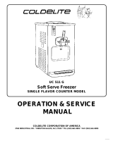
Model 750
Figure 4-1
14
6
13
8
9
10
11
7
5
4
12
2
1
15
3
16
17
Item Description Part No.
1 Cover A.-Hopper X38458-SER
2 Gasket-Hopper Cover 038375
3 Tube A.-Feed X29429-2
4 Panel-Rear 020891
5 Panel-Upper Side Right 042317
6 Pan-Drip 050766
7 Panel-Right Side 050742
8 Shield-Splash 022763
9 Tray-Drip 013690
Item Description Part No.
10 Panel-Side Left 050741
11 Leg-4” SS w/O-ring 013458
12 Louver-Side 051192
13 Stud-Nose Cone 022822
14 Panel A.-Front X50754
15 O-ring-.643 OD x .077 W 018572
16 O-ring-3/8 OD x .070 W 016137
17 Orifice 022465-100

4-2
OPERATOR PARTS IDENTIFICATION
Models 750, 751, 754, 774, 791, and 794
Operator Parts Identification
4
Model 751
Figure 4-2
13
8
9
4
11
7
20
5
4
18
2
1
15
3
16
17
12
21
14
10
19
6
18
Item Description Part No.
1 Cover A.-Hopper X38458-SER
2 Gasket-Hopper Cover 038375
3 Tube A.-Feed X29429-2
4 Panel-Rear 013637
5 Panel-Upper Side Right 028823
6 Pan-Drip 11-5/8 Long 027503
7 Panel A.-Lower Side Right X24424-SER
8 Shield-Splash 022763
9 Tray-Drip 14-7/8 x 5-1/8 013690
10 Panel-Upper Side 024426
11 Panel-Service 047170
Item Description Part No.
12 Caster-Swivel 018794
13 Stud-Nose Cone 022822
14 Panel A.-Side-Lower X39075-SER
15 O-ring-.643 OD x .077 W 018572
16 O-ring-3/8 OD x .070 W 016137
17 Orifice 022465-100
18 Louver-Side-Top 051191
19 Panel A.-Front X33237
20 Adaptor A.-Caster X18915
21 Caster-4 Swivel 5/8” Stem w/
Brake
034081

OPERATOR PARTS IDENTIFICATION
4-3
Models 750, 751, 754, 774, 791, and 794
Operator Parts Identification
4
Model 754
Figure 4-3
12
18
19
8
9
13
10
6
5
4
11
2
1
15
3
16
17
7
20
14
Item Description Part No.
1 Cover A.-Hopper X38458-SER
2 Gasket-Hopper Cover 038474
3 Tube A.-Feed X29429-2
4 Panel-Rear 053782
5 Panel-Upper Side Right 028823
6 Panel A.-Side Lower Right X46448-SER
7 Panel-Service 046584
8 Shield-Splash 022766
9 Tray-Drip 014533
10 Caster-Swivel 018794
Item Description Part No.
11 Panel-Upper Side Left 028822
12 Stud-Nose Cone 022822
13 Panel A.-Side Lower Left X46447-SER
14 Louver-Side-Top 051191
15 O-ring-.643 OD x .077 W 018572
16 O-ring-3/8 OD x .070 W 016137
17 Orifice 022465-100
18 Pan-Drip 17-1/4” Long 027504
19 Panel A.-Front X32956
20 Adaptor A.-Caster X18915

4-4
OPERATOR PARTS IDENTIFICATION
Models 750, 751, 754, 774, 791, and 794
Operator Parts Identification
4
Model 774
Figure 4-4
14
19
18
8
9
20
25
6
5
4
11
2
1
15
3
22
23
16
12
13
21
17
10
7
24
Item Description Part No.
1 Cover A.-Hopper X38458-SER
2 Gasket-Hopper Cover 20 Qt. 038474
3 Tube A.-Feed X29429-2
4 Panel-Upper Rear Inactive X42574
5 Louver-Side-Top 051191
6 Panel A.-Side Lower-Right X46448-SER
7 Panel-Service 047077
8 Shield-Splash 022766
9 Tray-Drip 014533
10 Caster-4” Swivel 5/8 Stem/Brake 034081
11 Panel-Upper Side Left 028822
12 Pan-Drip 17-1/4” Long 027504
13 Lid with Ladle 1 oz. 036575
Item Description Part No.
14 Pump A.-Syrup-Tan 053794-TAN
15 O-ring-.643 OD x .077 W 018572
16 Panel A.-Side Lower-Left X46447-SER
17 Jar-Syrup-Plastic Shallow 036573
18 Jar-Syrup-Stainless-Shallow 036574
19 Stud-Nose Cone 022822
20 Caster-4” Swivel 5/8” Stem 018794
21 Panel-Lower Rear Inactive 053837
22 O-ring-3/8 OD x .070 W 016137
23 Orifice 022465-100
24 Panel A.-Front-Syrup Inactive X42539
25 Adaptor A.-Caster X18915

OPERATOR PARTS IDENTIFICATION
4-5
Models 750, 751, 754, 774, 791, and 794
Operator Parts Identification
4
Model 774 Topping Pump (053794-)
Figure 4-5
8
5
4
3
1
9
17
16
14
10a
13
2
10
7
6
15
12
11
Item Description Part No.
1 Knob-Plunger-Tan 032762-TAN
1 Knob-Plunger-Brown 032762-BRN
1 Knob-Plunger-Red 032762-RED
2 O-ring-9/16 OD x .103 W 016369
3 Nut-Plunger 036577
4 Collar-Gaging 1/2 oz. 035514
5 Tube-Plunger 032757
6 Insert-Plunger 032758
7 Spring-Plunger 032761
8 Washer-Nylon 032760
9 Plunger 036578
10 Seal Assembly X33057
10a O-ring-13/16 OD x .103 W 019330
11 Body-Syrup Pump 047934
12 Nut-Spout 036821
13 Lid-Pump 036822
14 Tube-Discharge 050912
15 O-ring-1-5/16 OD x .103 W 048149
16 O-ring-1 OD x .103 W 048148
17 Kit-Valve-Captured Ball Shallow 048166-001
Includes:
1 - Body A.-Pump Valve
1 - O-ring-1-5/16 OD x .103W (048149)
1 - Brush-Cleaning (054068)
1 - Instruction Sheet-Installation/Cleaning

4-6
OPERATOR PARTS IDENTIFICATION
Models 750, 751, 754, 774, 791, and 794
Operator Parts Identification
4
Model 791
Figure 4-6
3
4
10
9
8
11
7
2
1
5
3
6
Item Description Part No.
1 Panel A.-Front X41820-SP3
2 Stud-Nose Cone 068410
3 Panel-Side 069038
4 Kit A.-Cover-Hopper X68150
5 Tube A.-Feed-SS-5/32 X29429-2
6 Panel-Rear 041855
Item Description Part No.
7 Caster-4” SWV 5/8 Stem 018794
8 Caster-4” SWV 5/8 Stem W/Brake 034081
9 Tray-Drip 16-7/8L x 5-1/8 020157
10 Shield-Splash 022765
11 Pan-Drip 19-1/2 Long 035034

OPERATOR PARTS IDENTIFICATION
4-7
Models 750, 751, 754, 774, 791, and 794
Operator Parts Identification
4
Model 794
Figure 4-7
17
13
8
9
12
10
11
6
4
5
2
1
15
3
14
16
7
Item Description Part No.
1 Cover-Hopper-14 Qt 041682-GRY
2 Pan-Drip 19 1/2 Long 035034
3 Tube A.-Feed X29429-2
4 Panel-Rear 041855
5 Panel-Side *Left 068691
6 Panel-Side *Right 068692
7 Panel-Service 064000
8 Shield-Splash 022765
9 Tray-Drip 021057
Item Description Part No.
10 Caster-4” SWV 5/8 Stem 018794
11 Adaptor A.-Caster X18915
12 Caster-4” SWV 5/8 Stem w/Brake 034081
13 Stud-Nose Cone 022822
14 O-ring-3/8 OD x .070W 016137
15 O-ring-.643 OD x .077W 018572
16 Orifice 022465-100
17 Panel A.-Front X41820-SP3

4-8
OPERATOR PARTS IDENTIFICATION
Models 750, 751, 754, 774, 791, and 794
Operator Parts Identification
4
Models 750 and 751 Single-Spout Door and Beater Assembly
Figure 4-8
14
2
13
8
11
3
15
16
12
6
1a
10
9
4
1b
1c
7
5
1
Item Description Part No.
1 Handle A.-Draw Nonadj X69016
1a Draw Handle 028804
1b Screw-Adjustment 069014
1c O-ring 1/4OD x .070W 015872
2 Nut-Stud Flat Long 021508
3 Door A.- 1-Spout X51531-10
4 Valve A.- Draw X18303
5 O-ring 7/8OD x .070W 014402
6 Cap-Design 014218
7 O-ring 5/16OD x .070W 016272
Item Description Part No.
8 Plug-Prime 028805
9 O-ring-Prime Plug 016137
10 Pin A.- Pivot X22820
11 Gasket-Door HT 4" 048926
12 Blade- Scraper 035174
13 Beater A.- Helicore X31761
14 Bearing-Front 050216
15 Shaft-Beater 032564
16 Seal-Drive Shaft 032560
/