Page is loading ...

Weather Station ·
ClimaTemp XXL + Multisensor-Set
EN Instruction manual

DE
Besuchen Sie unsere Website über den folgenden QR Code oder Weblink um weitere
Informationen zu diesem Produkt oder die verfügbaren Übersetzungen dieser Anleitung zu
finden.
EN
Visit our website via the following QR Code or web link to find further information on this
product or the available translations of these instructions.
FR
Si vous souhaitez obtenir plus d’informations concernant ce produit ou rechercher ce mode
d’emploi en d’autres langues, rendez-vous sur notre site Internet en utilisant le code QR ou le
lien correspondant.
NL
Bezoek onze internetpagina via de volgende QR-code of weblink, voor meer informatie over dit
product of de beschikbare vertalingen van deze gebruiksaanwijzing.
IT
Desidera ricevere informazioni esaustive su questo prodotto in una lingua specifica? Venga
a visitare il nostro sito Web al seguente link (codice QR Code) per conoscere le versioni
disponibili.
ES
¿Desearía recibir unas instrucciones de uso completas sobre este producto en un idioma
determinado? Entonces visite nuestra página web utilizando el siguiente enlace (código QR)
para ver las versiones disponibles.
CA
Voleu una guia detallada d'aquest producte en un idioma específic? Visiteu el nostre lloc web
a través del següent enllaç (codi QR) per accedir a les versions disponibles.
PT
Deseja um manual detalhado deste produto numa determinada língua? Visite a nossa Website
através da seguinte ligação (QR Code) das versões disponíveis.
www.bresser.de/P7002420
www.bresser.de/warranty_terms
GARANTIE · WARRANTY · GARANTÍA · GARANZIA

3
Contents
1 Imprint (German) ............................................................................................................................................4
2 Validity note ....................................................................................................................................................4
3 About this Instruction Manual.......................................................................................................................4
4 General safety instructions ...........................................................................................................................4
5 Parts overview Base station..........................................................................................................................6
6 Parts overview Multisensor Set ....................................................................................................................7
7 Scope of delivery............................................................................................................................................7
8 Screen display ................................................................................................................................................8
9 Before starting operation...............................................................................................................................9
10 Setting up power supply................................................................................................................................9
11 Installing the multisensor set......................................................................................................................10
12 Automatic time setting.................................................................................................................................11
13 Manual time setting and other user defined settings ...............................................................................11
14 Setting the wind direction............................................................................................................................11
15 Time zone setting .........................................................................................................................................11
16 Display change .............................................................................................................................................12
17 Alarm setting.................................................................................................................................................12
18 Temperature alarm setting ..........................................................................................................................12
19 Receiving measurements automatically ....................................................................................................13
20 Temperature alarm setting ..........................................................................................................................13
21 Precipitation..................................................................................................................................................13
22 Set weather status and air pressure above N.N ........................................................................................13
23 Weather trend ...............................................................................................................................................14
24 Barometric / Atmospheric Pressure ...........................................................................................................14
25 Wind speed and direction............................................................................................................................15
26 Wind chill factor............................................................................................................................................16
27 EC Declaration of Conformity .....................................................................................................................16
28 Disposal.........................................................................................................................................................16
29 Warranty ........................................................................................................................................................17

4 / 20
1 Imprint (German)
Bresser GmbH
Gutenbergstr. 2
46414 Rhede
Germany
http://www.bresser.de
For any warranty claims or service enquiries, please refer to the information on "Warranty" and "Ser-
vice" in this documentation. We apologize for any inconvenience caused by the fact that we cannot
process enquiries or submissions sent directly to the manufacturer's address.
Errors and technical changes excepted.
© 2019 Bresser GmbH
All rights reserved.
The reproduction of this documentation - even in extracts - in any form (e.g. photocopy, print, etc.) as
well as the use and distribution by means of electronic systems (e.g. image file, website, etc.) without
the prior written permission of the manufacturer is prohibited.
The designations and brand names of the respective companies used in this documentation are gen-
erally protected by trade, trademark and/or patent law in Germany, the European Union and/or other
countries.
2 Validity note
This documentation is valid for the products with the following article numbers:
7002420
Manual version: 0919
Manual designation:
Manual_7002420_ClimaTemp-XXL_en_BRESSER_v092019a
Always provide information when requesting service.
3 About this Instruction Manual
NOTICE
These operating instructions are to be considered a component of the device.
Read the safety instructions and the operating manual carefully before using this device.
Keep this manual in a safe place for future reference. When the device is sold or given to someone
else, the instruction manual must be provided to the new owner/user of the product.
4 General safety instructions
DANGER
Danger of suffocation!
Improper use of this product may result in suffocation, especially for children. It is therefore imperative
that you observe the following safety information.
• Keep packaging materials (plastic bags, rubber bands, etc.) away from children! There is a
DANGER OF CHOKING [These pose a CHOKING HAZZARD]

5 / 20
• This product contains small parts that can be swallowed by children! There is a DANGER OF
CHOKING [These pose a CHOKING HAZZARD]
DANGER
Risk of electric shock
This device has electronic parts operated via a power source (power supply and/or batteries). Im-
proper use of this product can cause an electric shock. An electric shock can cause serious or poten-
tially fatal injuries. The following safety information must be observed at all times.
• Children must only use the device under adult supervision! Only use the device as described in the
manual; otherwise, you run the risk of an electric shock.
DANGER
Risk of explosion
Improper use of this product can cause an explosion. The following safety information must be ob-
served at all times to prevent an explosion.
• Do not expose the device to high temperatures. Use only the recommended batteries. Do not
short-circuit the device or batteries, or throw them into a fire! Excessive heat or improper handling
could trigger a short-circuit, a fire or an explosion!
NOTICE
DANGER of material damage!
Improper handling may result in damage to the unit and/or accessories. Therefore, use the device only
in accordance with the following safety information.
• Never disassemble the device. In the event of a fault, please contact your specialist retailer. The
specialist retailer will contact the service centre and send the device for repair if necessary.
• Do not immerse the unit in water!
• Do not expose the device to impacts, vibrations, dust, constant high temperatures or excessive hu-
midity. This can result in malfunctions, short-circuits or damage to the batteries and components.
• Use only the recommended batteries. Always replace weak or empty batteries with a new, com-
plete set of batteries at full capacity. Do not use batteries from different brands or with different ca-
pacities. Remove the batteries from the unit if it has not been used for a long time.
NOTICE
Risk of voltage damage!
The manufacturer is not liable for damage related to improperly installed batteries!

6 / 20
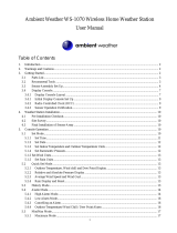
5 Parts overview Base station
4
5
6
11
13
10
9
14
15
8
1
3
2
12
7
A
Illustration1: All parts of the base station
1 Housing 2 Display
3 Indoor sensor 4 MODE/SET button (change display mode
or settings)
5 DOWN/RAIN HISTORY button (decrease
value or show 30 days precipitation his-
tory)
6 UP/RCC/ALARM button (increase value or
enable alarm)
7 RAIN SINCE/CLEAR button (show precip-
itation since last reset or delete stored
precipitation values)
8 Wall mount fixture
9 WEATHER/ABS/REL button (set weather
or change barometric pressure type)
10 RESET button (reset all settings)
11 Stand, fold-out 12 Battery compartment
Battery compartment cover 14 RAIN ALERT button (set and enable pre-
cipitation alert)
15 OUT-TEMP ALERT button (set and en-
able outdoor temperature alert)

7 / 20
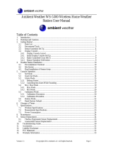
6 Parts overview Multisensor Set
3
2
1
4
5
6
7
8
9
12
11
10
14
13
15
16
16
17
18
B
C
D
E
Illustration2: Multisensor Set: Thermo-hygrometer (top left) and windmeter/rain gauge (right)
1 Wall mount fixture 2 Signal transmission indicator
3 Display 4 Housing
5 °C/°F button (display change between °C
or °F)
6 RESET button (reset all settings)
7 Battery compartment 8 Modular plug
9 Battery compartment cover 10 Wind vane
11 Wind cups 12 Rain gauge
13 Connection cable with modular plug 14 Mounting tube (severeal parts)
15 Mounting shoe 16 Fixing screws
17 Tube clamps 18 Mounting screws and nuts
7 Scope of delivery
Base unit (A), thermo-hygrometer (B), windmeter/rain gauge (C), connection cable (D), mounting
utensils (E)
Also required (not included):
Station: 2 pcs. Mignon batteries (1.5V, AA type)
Sensor: 3 pcs. Mignon batteries (1.5V, AA type)
Small Phillips screwdriver

8 / 20
8 Screen display
1
2
3
4
5
6
9
8
7
10
11
12
21
19
18
17
16
15
14
13
2022
23
Illustration3: Screen display of the base station
1 AM/PM information in 12-hour time mode 2 Current time (hours:minutes:seconds)
3 Beaufort scale for wind force classification
(1 to 12)
4 Outdoor sensor symbol (when measure-
ment values are displayed)
5 Wind speed in km/h 6 Wind gust
7 Wind chill (in °C or °F) 8 Total precipitation (30 days) (in MM)
9 Daily precipitation (24 hours) (in MM) 10 Indoor temperature (in °C or °F)
11 Outdoor temperature (in °C or °F) 12 Humidity outdoors (in %)
13 Humidity indoors (in %) 14 Higheset/lowest value for outdoor temper-
ature (24 hours history)
15 Wind direction 16 Barometric pressure type (ABS = absolute
or REL = relative)
17 Symbol for barometric pressure tendence
(rising, steady or falling)
18 Barometric pressure value (in MB/HPA)
19 Weather forecast 20 Symbol for radio signal

9 / 20
21 Current time (seconds) or weekday or
alarm time (display depends on the selec-
ted display mode)
22 Symbol for active alarm
23 Moon phase
9 Before starting operation
NOTICE
Avoid connectivity disruptions!
To avoid connectivity disruptions between the devices, consider the following points before starting
operation.
1. Place base station (receiver) and remote sensor (sender) together as close as possible.
2. Set up power supply for the base station and wait until the indoor temperature is displayed.
3. Set up power supply for the remote sensor.
4. Position the base station and the remote sensor within the effective transmission range.
5. Ensure that the base station and remote sensor are assigned to the same channel.
When changing batteries always change batteries in the main unit as well as all remote units and re-
place them in the correct order, so the remote connection can be re-established. If either of the
devices is mains-powered, the power supply must be disconnected for a short moment also for this
device when exchanging the batteries. If batteries are exchanged in only one of the devices (i.e. the
remote sensor) the signal can’t be received or can’t be received correctly.
Note, that the effective range is vastly affected by building materials and position of the main and re-
mote units. Due to external influences (various RC devices and other sources of interference), the
maximum distance can be greatly reduced. In such cases we suggest to position the main unit and the
remote sensor at other places. Sometimes all it takes is a relocation of one of these components of a
few inches!
10 Setting up power supply
Base unit
1. Remove the battery compartment cover.
2. Insert the batteries into the battery compartment. Ensure that the battery polarity (+/-) is correct.
3. Replace the battery compartment cover.
Thermo-Hygrometer
4. Remove the battery compartment cover.
5. Insert the batteries into the battery compartment. Ensure that the battery polarity (+/-) is correct.
6. Replace the battery compartment cover.
NOTICE!The power supply of the wind / rain gauge is ensured via the cable connection to the
thermo-hygrometer. (For more information, see the chapter 'Installing the multisensor set')

10 / 20
11 Installing the multisensor set
Illustration4: Mounting example
1. Assemble the individual parts of the mounting tube.
2. Carefully run the connection cable from the windmeter / rain gauge through the mounting tube and
the mounting shoe.
3. Insert one end of the mounting tube into the opening below the windmeter / rain gauge and the
other end into the opening of the mounting shoe.
CAUTION!Make sure that the cable is not being damaged when inserting the tube!

11 / 20
4. Attach the windmeter/rain gauge and the mounting shoe to the mounting tube with the fixing
screws through the drill holes.
5. Attach the mounting shoe to a horizontally and vertically aligned pole or a wall with the enclosed
mounting material in at least 2 meters height.
6. Remove the battery compartment cover of the thermo-hygrosensor.
7. Insert the modular plug on the other end of the cable into the modular socket of the thermo-hygro
sensor.
CAUTION!Before inserting or removing the modular plug, press down the locking lug!
8. Mount the thermo-hygrosensor below the windmeter/rain gauge.
12 Automatic time setting
After the power supply was established, the clock will automatically search for the radio signal. The
clock will automatically search for the radio signal.
If the radio signal is received correctly, the date and time will be set automatically and the radio control
signal icon turns on.
If the clock fails to receive the time signal, go ahead with the following steps:
1. Press DOWN/RAIN HISTORY button and UP/RCC/ALARM button for approx. 2 seconds to re-initi-
ate radio signal reception.
2. If the device is still not receiving the signal, the time must be set manually.
Read the detailed manual for more information about manual time setting and other user defined set-
tings (see download information on page 2).
13 Manual time setting and other user defined
settings
1. In normal display mode, press MODE/SET button for approx. 3 seconds to switch to settings
mode.
2. Digits to be set are flashing.
3. Press DOWN/RAIN HISTORY button or UP/RCC/ALARM button to change the value.
4. Press the MODE/SET button to confirm the setting and move to the next setting.
5. Settings order: 12/24 hours mode > RCC on/off > time zone (-12 to +12 hours) > hours > minutes
> seconds > year > month > day > language > temperature unit > barometric pressure unit > wind
speed unit > precipitation unit > wind direction
6. Finally press MODE/SET button to save the settings and exit settings mode.
14 Setting the wind direction
To adjust the wind direction, proceed as follows:
1. Press the MODE/SET button for approx. 3 seconds to enter the settings mode.
2. Press the MODE/SET button repeatedly until the wind direction setting is shown in the display at
the end (all directions flash).
3. Align the wind vane with the wind turbine in a northerly direction (tip points north).
4. Press the UP/RCC/ALARM or DOWN/RAIN HISTORY button to set the wind direction indicator on
the display to North.
5. Press the MODE/SET button to confirm the setting.
15 Time zone setting
To set a different time zone, proceed as follows:

12 / 20
1. Press and hold MODE button for approx. 3 seconds to change to time setting mode.
2. Press the MODE button multiple times until the display shows the time offset 00 Hr.
3. Press UP or DOWN button to select the desired time deviation in hours (-23 up to +23 hours).
4. Finally press the MODE button to save the settings and exit the setting mode.
16 Display change
In normal display mode, press the DOWN/RCC button to toggle the time display between 12-hour or
24-hour mode (AM/PM time information is displayed or hidden accordingly)
In normal display mode, press the UP/CF button to toggle between °C and °F when displaying the
temperature unit.
In normal display mode, press the CH button several times to display channels 1, 2, 3 or automatically
alternating one after another.
NOTICE!The display of values for different channels requires the connection of several suitable
wireless sensors (not included).
In normal display mode, press the ALERT button several times to display the set temperature alarm
values one after another.
17 Alarm setting
1. Press MODE button to switch to alarm time display.
2. Press and hold ALARM button for approx. 2 seconds to enter the alarm time setting mode (AL).
3. Digits to be set are flashing.
4. Press UP or DOWN button to change the value.
5. Press ALARM button to confirm and continue to the next setting.
6. Settings order: Hours > Minutes
7. Finally press the ALARM button to save the settings and exit the setting mode. Alarm will be activ-
ated automatically. The symbol will be displayed.
8. Press MODE button in normal display mode to display the alarm time.
9. Press ALARM button during the alarm time display to disable the alarm. The symbol will not be
displayed.
18 Temperature alarm setting
1. In normal time display mode, press DOWN button for approx. 2 seconds to enter temperature
alarm time setting mode.
2. Digits to be set are flashing.
3. Settings order: ON/OFF (Temperature alarm on/off) > Temperature highest limit > Temperature
lowest limit > Exit
4. Press UP or DOWN button to change the value.
5. Press SET button to confirm and continue to the next setting.
6. The temperature settings mode will be quit automatically after 30 seconds of inactivity. All settings
done before will be saved.
7. When outdoor temperature reaches highest or lowest limit, the temperature alarm symbol will flash
and an alarm will sound for approx. 3 seonds. This will be repeated with an interval of 1 minute un-
til the temperature has fallen below the limit again.
NOTICE!NOTICE! Select temperature alarm OFF from the temperature settings mode to dis-
abled the temperature alarm permanently.

13 / 20
19 Receiving measurements automatically
Once batteries are installed, the base station will display the measurement readings. Readings from
the remote sensor will be displayed within 3 minutes after powering it on.
20 Temperature alarm setting
1. In normal time display mode, press DOWN button for approx. 2 seconds to enter temperature
alarm time setting mode.
2. Digits to be set are flashing.
3. Settings order: ON/OFF (Temperature alarm on/off) > Temperature highest limit > Temperature
lowest limit > Exit
4. Press UP or DOWN button to change the value.
5. Press SET button to confirm and continue to the next setting.
6. The temperature settings mode will be quit automatically after 30 seconds of inactivity. All settings
done before will be saved.
7. When outdoor temperature reaches highest or lowest limit, the temperature alarm symbol will flash
and an alarm will sound for approx. 3 seonds. This will be repeated with an interval of 1 minute un-
til the temperature has fallen below the limit again.
NOTICE!NOTICE! Select temperature alarm OFF from the temperature settings mode to dis-
abled the temperature alarm permanently.
21 Precipitation
The precipitation which was collected over a certain period is displayed on the base station in milli-
meters or inches and is based on the current precipitation rate.
Rainfall rate Daily rainfall Weekly rainfall Monthly rainfall
Select display mode
Press the RAIN button several times until the desired time range is displayed:
RATE Current precipitation rate in the past hour
DAILY Total precipitation rate of the current day, measured from midnight
WEEKLY Total precipitation rate of the current week
MONTHLY Total precipitation rate of the current month
Select measurement unit (millimeters or inch)
1. Press the RAIN button for approx. 3 seconds to change to measurement unit settings.
2. Press UP or DOWN button to change between mm (millimeters) and in (inch).
3. Finally press the RAIN button to save the settings and exit the setting mode.
NOTICE!Readings are updated automatically every 6 minutes.
22 Set weather status and air pressure above N.N
NOTICE!For a correct display of the weather forecast, the current weather status and the air
pressure above N.N. must be set correctly immediately after commissioning. The first weather
forecast will be displayed approximately 6 hours after the set-up.

14 / 20
NOTICE!These settings should also be made again when chnaging the location of the unit.
1. After switching on the unit, press the WEATHER/ABS/REL button for 3 seconds. The weather
symbol on the display flashes.
2. Select the graphic symbol corresponding with the current weather status by pressing the UP or
DOWN button.
3. Press WEATHER/ABS/REL button to enter the next setting. The air pressure value flashes.
4. Set the current value for the air pressure above N.N. by pressing the UP or DOWN key.
5. NOTICE!Information on the current value for the air pressure above N.N. can be found on
the Internet at https://www.dwd.de/DE/leistungen/beobachtung/beobachtung.html
6. Finally, press the WEATHER/ABS/REL button to save the settings and return to the normal display
mode.
23 Weather trend
The weather station will calculate a weather trend for the next 12 hours on basis of the measured val-
ues.
1
2
3
4
5
Illustration5: Weather trend indicators
1 Sunny 2 Partly cloudy
3 Cloudy 4 Rain
5 Snow
24 Barometric / Atmospheric Pressure
Atmospheric Pressure is the pressure at any location on earth, caused by the weight of the column of
air above it. One atmospheric pressure refers to the average pressure and gradually decreases as alti-
tude increases. Meteorologists use barometers to measure atmospheric pressure. Since variation in
atmospheric pressure is greatly affected by weather, it is possible to forecast the weather by measur-
ing the changes in pressure.
1. Press the BARO button to enter the setting mode.
2. Press the BARO button again, to change the unit between inHg / mmHg / hPa.
3. Press the BARO button for 3 seconds to change between absolute and relative atmospheric pres-
sure.
• ABSOLUTE: the absolute atmospheric pressure of your location.
• RELATIVE: the relative atmospheric pressure based on the sea level.
Set relative atmospheric pressure value
4. Get the atmospheric pressure data of the sea level (it is also the relative atmospheric pressure
data of your home area) through the local weather service, internet and other channels.
5. Hold the BARO button for approx. 3 seconds, until ABSOLUTE or RELATIVE flashes.

15 / 20
6. Press the UP or DOWN button to switch to RELATIVE mode.
7. Press the BARO button again, and the number for RELATIVE flashes.
8. Press UP or DOWN button to change the value.
9. Press the BARO button to save and exit the setting mode.
NOTE
10. The default relative atmospheric pressure value is 1013 mb/hPa (29.91 inHg), which refers to the
average atmospheric pressure.
11. When you change the relative atmospheric pressure value, the weather indicators will change
along with it.
12. The built-in barometer can notice the environmental absolute atmospheric pressure changes.
Based on the data collected, it can predict the weather conditions in the forthcoming 12 hours.
Therefore, the weather indicators will change according to the detected absolute atmospheric
pressure after you operate the clock for 1 hour.
13. The relative atmospheric pressure is based on the sea level, but it will change with the absolute at-
mospheric pressure changes after operating the clock for 1 hour.
25 Wind speed and direction
Reading the wind direction
Wind direction indic-
ator
Meaning
Real-time wind direction
Wind directions appeared in the last 5 minutes (max. 6)
Select display mode
Press the WIND button several times until the desired rate is displayed:
• AVERAGE: average of all wind speed numbers recorded in the previous 30 seconds
• GUST: highest wind speed (gust) recorded from last reading

16 / 20
The wind level provides a quick reference on the wind condition and is indicated by a series of text
icons:
Wind level LIGHT MODERATE STRONG STORM
Speed 1 – 19 km/h 20 – 49 km/h 50 – 88 km/h > 88 km/h
Select wind speed unit
1. Press the WIND button for approx. 3 seconds to enter the setting mode.
2. Press the UP or DOWN button to change the unit between mph (miles per hour), m/s (miles per
second), km/h (kilometer per hour) or knots.
3. Press the WIND button to save the settings and exit the setting mode.
26 Wind chill factor
Press the INDEX button several times until WIND CHILL is displayed.
Note:
The wind chill factor is based on the common effects of temperature and wind speed.The displayed
wind chill is calculated solely from temperature and wind speed and is measured by the outdoor
sensor.
27 EC Declaration of Conformity
Hereby, Bresser GmbH declares that the equipment type with item number 7002420 : is in compli-
ance with Directive: 2014/30/EU. The full text of the EU declaration of conformity is available at the
following internet address: www.bresser.de/download/7002420/CE/7002420_CE.pdf
28 Disposal
Dispose of the packaging materials properly, according to their type, such as paper or card-
board. Contact your local waste-disposal service or environmental authority for information
on the proper disposal.
Do not dispose of electronic devices in the household garbage!
As per Directive 2012/19/EC of the European Parliament on waste electrical and electronic
equipment and its adaptation into German law, used electronic devices must be collected
separately and recycled in an environmentally friendly manner.
Do not dispose of batteries and rechargeable batteries with the household waste. You are leg-
ally required to return used batteries and rechargeable batteries. After they are used, the bat-
teries can be returned free of charge to our point of sale or to a nearby location (for example,
retailers or municipal collecting points).

17 / 20
Batteries and rechargeable batteries are marked with a symbol of a crossed-out dustbin and
the chemical symbol of the pollutant. “Cd” stands for Cadmium, “Hg” stands for mercury and
“Pb” stands for lead.
29 Warranty
The regular guarantee period is 2 years and begins on the day of purchase. To benefit from an exten-
ded voluntary guarantee period as stated on the gift box, registration on our website is required.
You can consult the full guarantee terms as well as information on extending the guarantee period and
details of our services at www.bresser.de/warranty_terms.


DE
AT
CH
BE
Bei Fragen zum Produkt und eventuellen
Reklamationen nehmen Sie bitte zunächst mit
dem Service-Center Kontakt auf, vorzugsweise
per E-Mail.
E-Mail: service@bresser.de
Telefon*: +49 28 72 80 74 210
BRESSER GmbH
Kundenservice
Gutenbergstr. 2
46414 Rhede
Deutschland
* Lokale Rufnummer in Deutschland (Die Höhe der Gebühren je
Telefonat ist abhängig vom Tarif Ihres Telefonanbieters); Anrufe aus
dem Ausland sind mit höheren Kosten verbunden.
GB
IE
Please contact the service centre first for any
questions regarding the product or claims,
preferably by e-mail.
e-mail: ser[email protected]
Telephone*: +44 1342 837 098
BRESSER UK Ltd
Suite G3, Eden House
Enterprise Way
Edenbridge, Kent TN8 6HF
United Kingdom
* Number charged at local rates in the UK (the amount you will be
charged per phone call will depend on the tariff of your phone
provider); calls from abroad will involve higher costs.
FR
BE
Si vous avez des questions concernant ce
produit ou en cas de réclamations, veuillez
prendre contact avec notre centre de services
(de préférence via e-mail).
e-mail: sav@bresser.fr
Téléphone*: 00 800 6343 7000
BRESSER France SARL
Pôle d'Activités de Nicopolis
260, rue des Romarins
83170 Brignoles
France
* Prix d'un appel local depuis la France ou Belgique
Service
NL
BE
Als u met betrekking tot het product vragen
of eventuele klachten heeft kunt u contact
opnemen met het service centrum (bij voorkeur
per e-mail).
e-mail: [email protected]
Teléfono*: +31 528 23 24 76
Folux B.V.
Smirnoffstraat 8
7903 AX Hoogeveen
Nederlands
* Het telefoonnummer wordt in het Nederland tegen lokaal tarief
in rekening gebracht. Het bedrag dat u per gesprek in rekening
gebracht zal worden, is afhankelijk van het tarief van uw telefoon
provider; gesprekken vanuit het buitenland zullen hogere kosten
met zich meebrengen.
ES
PT
Si desea formular alguna pregunta sobre el
producto o alguna eventual reclamación, le
rogamos que se ponga en contacto con el
centro de servicio técnico (de preferencia por
e-mail).
e-mail: servicio.iberia@bresser-iberia.
es
Teléfono*: +34 91 67972 69
BRESSER Iberia SLU
c/Valdemorillo,1 Nave B
P.I. Ventorro del cano
28925 Alcorcón Madrid
España
* Número local de España (el importe de cada llamada telefónica
dependen de las tarifas de los distribuidores); Las llamadas des del
extranjero están ligadas a costes suplementarios.
/