Page is loading ...

USER’S MANUAL
Revision 1.0
X10DAL-i

Manual Revision 1.0
Release Date: March 31, 2015
Unless you request and receive written permission from Super Micro Computer, Inc., you may not
copy any part of this document.
Information in this document is subject to change without notice. Other products and companies
referred to herein are trademarks or registered trademarks of their respective companies or mark
holders.
Copyright © 2015 by Super Micro Computer, Inc.
All rights reserved.
Printed in the United States of America
The information in this user’s manual has been carefully reviewed and is believed to be accurate.
The vendor assumes no responsibility for any inaccuracies that may be contained in this document,
and makes no commitment to update or to keep current the information in this manual, or to notify
any person or organization of the updates. Please Note: For the most up-to-date version of this
manual, please see our Website at www.supermicro.com.
Super Micro Computer, Inc. ("Supermicro") reserves the right to make changes to the product
described in this manual at any time and without notice. This product, including software and docu-
mentation, is the property of Supermicro and/or its licensors, and is supplied only under a license.
Any use or reproduction of this product is not allowed, except as expressly permitted by the terms
of said license.
IN NO EVENT WILL SUPER MICRO COMPUTER, INC. BE LIABLE FOR DIRECT, INDIRECT,
SPECIAL, INCIDENTAL, SPECULATIVE OR CONSEQUENTIAL DAMAGES ARISING FROM THE
USE OR INABILITY TO USE THIS PRODUCT OR DOCUMENTATION, EVEN IF ADVISED OF
THE POSSIBILITY OF SUCH DAMAGES. IN PARTICULAR, SUPER MICRO COMPUTER, INC.
SHALL NOT HAVE LIABILITY FOR ANY HARDWARE, SOFTWARE, OR DATA STORED OR USED
WITH THE PRODUCT, INCLUDING THE COSTS OF REPAIRING, REPLACING, INTEGRATING,
INSTALLING OR RECOVERING SUCH HARDWARE, SOFTWARE, OR DATA.
Any disputes arising between the manufacturer and the customer shall be governed by the laws of
Santa Clara County in the State of California, USA. The State of California, County of Santa Clara
shall be the exclusive venue for the resolution of any such disputes. Supermicro's total liability for
all claims will not exceed the price paid for the hardware product.
FCC Statement: This equipment has been tested and found to comply with the limits for a Class
A digital device pursuant to Part 15 of the FCC Rules. These limits are designed to provide
reasonable protection against harmful interference when the equipment is operated in a commercial
environment. This equipment generates, uses, and can radiate radio frequency energy and, if not
installed and used in accordance with the manufacturer’s instruction manual, may cause harmful
interference with radio communications. Operation of this equipment in a residential area is likely
to cause harmful interference, in which case you will be required to correct the interference at your
own expense.
California Best Management Practices Regulations for Perchlorate Materials: This Perchlorate
warning applies only to products containing CR (Manganese Dioxide) Lithium coin cells. “Perchlorate
Material-special handling may apply. See www.dtsc.ca.gov/hazardouswaste/perchlorate”.
WARNING: Handling of lead solder materials used in this
product may expose you to lead, a chemical known to
the State of California to cause birth defects and other
reproductive harm.

Preface
This manual is written for system integrators, PC technicians, IT professionals, and
knowledgeable end users. It provides information for the installation and use of the
X10DAL-i motherboard.
About This Motherboard
The Super X10DAL-i motherboard supports dual Intel E5-2600v3 Series proces-
sors (Socket R3) that offer Intel Microarchitecture 22nm Processing Technology,
delivering performance, power efciency, and feature sets optimized for small-form
factor workstation platforms. With the PCH C612 built in, the X10DAL-i motherboard
supports Intel® Node Manager 3.0, Intel® Management Engine, Intel® Thunderbolt
Technology, and 2133 MHz DDR4 memory. This motherboard is ideal for worksta-
tions used for medical imaging applications. Please refer to our website (http://www.
supermicro.com) for CPU and memory support updates.
Manual Organization
Chapter 1 describes the features, specications and performance of the mother-
board. It also provides detailed information about the Intel C612 chipset.
Chapter 2 provides hardware installation instructions. Read this chapter when in-
stalling the processor, memory modules, and other hardware components into the
system. If you encounter any problems, see Chapter 3, which describes trouble-
shooting procedures for video, memory, and system setup stored in the CMOS.
Chapter 4 includes an introduction to the BIOS, and provides detailed information
on running the CMOS setup utility.
Appendix A provides BIOS error beep codes.
Appendix B lists software installation instructions.
Appendix C details UEFI BIOS recovery instructions.
Preface
iii

iv
Conventions Used in the Manual
Pay special attention to the following symbols for proper system installation and to
prevent damage to the system or injury to yourself:
Warning: Important information given to ensure proper system installation or to avoid
damaging the components or the motherboard,
Note: Additional important information provided for correct system setup.
X10DAL-i Motherboard User's Manual

Preface
v
Contacting Supermicro
Headquarters
Address: Super Micro Computer, Inc.
980 Rock Ave.
San Jose, CA 95131 U.S.A.
Tel: +1 (408) 503-8000
Fax: +1 (408) 503-8008
Email: [email protected] (General Information)
[email protected] (Technical Support)
Website: www.supermicro.com
Europe
Address: Super Micro Computer B.V.
Het Sterrenbeeld 28, 5215 ML
's-Hertogenbosch, The Netherlands
Tel: +31 (0) 73-6400390
Fax: +31 (0) 73-6416525
Email: [email protected] (General Information)
[email protected] (Technical Support)
[email protected] (Customer Support)
Website: www.supermicro.nl
Asia-Pacic
Address: Super Micro Computer, Inc.
3F, No. 150, Jian 1st Rd.
Zhonghe Dist., New Taipei City 235
Taiwan (R.O.C)
Tel: +886-(2) 8226-3990
Fax: +886-(2) 8226-3992
Email: [email protected]
Website: www.supermicro.com.tw

vi
Table of Contents
Preface
About This Motherboard ................................................................................................ 3
Manual Organization ..................................................................................................... 3
Conventions Used in the Manual .................................................................................. 4
Contacting Supermicro .................................................................................................. 5
Chapter 1 Overview
1-1 Overview ......................................................................................................... 1-1
Checklist .......................................................................................................... 1-1
X10DAL-i Quick Reference ............................................................................. 1-4
Motherboard Features ..................................................................................... 1-7
1-2 Processor and Chipset Overview...................................................................1-11
1-3 Special Features ........................................................................................... 1-12
Recovery from AC Power Loss ..................................................................... 1-12
1-4 System Health Monitoring ............................................................................. 1-12
Fan Status Monitor with Firmware Control .................................................. 1-12
Environmental Temperature Control ............................................................. 1-12
System Resource Alert ................................................................................. 1-12
1-5 ACPI Features ............................................................................................... 1-13
1-6 Power Supply ................................................................................................ 1-13
1-7 Super I/O ....................................................................................................... 1-14
Chapter 2 Installation
2-1 Standardized Warning Statements ................................................................. 2-1
Battery Handling .............................................................................................. 2-1
Product Disposal ............................................................................................. 2-3
2-2 Static-Sensitive Devices .................................................................................. 2-4
Precautions ..................................................................................................... 2-4
Unpacking ....................................................................................................... 2-4
2-3 Motherboard Installation .................................................................................. 2-5
Tools Needed .................................................................................................. 2-5
Location of Mounting Holes ............................................................................ 2-5
Installing the Motherboard .............................................................................. 2-6
2-4 Processor and Heatsink Installation................................................................ 2-7
Installing the LGA2011 Processor ................................................................. 2-7
Installing a Passive CPU Heatsink ................................................................2-11
Removing the Heatsink ................................................................................. 2-12
2-5 Installing and Removing the Memory Modules ............................................. 2-13
X10DAL-i Motherboard User's Manual

vii
Table of Contents
Installing & Removing DIMMs ....................................................................... 2-13
Removing Memory Modules ......................................................................... 2-13
2-6 Control Panel Connectors and I/O Ports ...................................................... 2-16
Backpanel Connectors and I/O Ports ........................................................... 2-16
Ethernet Ports .......................................................................................... 2-17
Universal Serial Bus (USB) ...................................................................... 2-18
5.1 HD (High-Denition) Audio ................................................................ 2-19
Front Accessible Audio Header ................................................................ 2-19
Front Control Panel ....................................................................................... 2-20
Front Control Panel Pin Denitions............................................................... 2-21
NMI Button ............................................................................................... 2-21
Power LED .............................................................................................. 2-21
HDD LED .................................................................................................. 2-22
NIC1/NIC2 LED Indicators ....................................................................... 2-22
Overheat (OH)/Fan Fail LED.................................................................... 2-23
Power Fail LED ........................................................................................ 2-23
Reset Button ........................................................................................... 2-24
Power Button ........................................................................................... 2-24
2-7 Connecting Cables ........................................................................................ 2-25
Power Connectors ................................................................................... 2-25
Fan Headers ............................................................................................. 2-26
Chassis Intrusion ..................................................................................... 2-26
Internal Speaker ....................................................................................... 2-27
Power LED/Speaker ................................................................................. 2-27
TPM Header/Port 80 Header ................................................................... 2-28
Standby Power Header ............................................................................ 2-28
I-SGPIO 1/2 & S-SGPIO Headers ........................................................... 2-29
SATA_DOM Power Connectors ............................................................... 2-29
SPDIF_In/SPDIF_Out Headers ................................................................ 2-30
Power SMB (I
2
C) Connector .................................................................... 2-30
COM Header ............................................................................................ 2-31
2-8 Jumper Settings ............................................................................................ 2-32
Explanation of Jumpers ................................................................................ 2-32
GLAN Enable/Disable .............................................................................. 2-32
CMOS Clear ............................................................................................. 2-33
Watch Dog Enable/Disable ...................................................................... 2-33
I
2
C Bus to PCI-Exp. Slots ........................................................................ 2-34
Manufacturer Mode Select ....................................................................... 2-34

viii
Onboard Audio Enable ............................................................................. 2-35
USB 0/1 Wake-up Enable ........................................................................ 2-36
2-9 Onboard LED Indicators ............................................................................... 2-37
GLAN LEDs .............................................................................................. 2-37
Onboard Power LED ............................................................................... 2-37
2-10 SATA 3.0 Connections .................................................................................. 2-38
SATA 3.0 Connections .............................................................................. 2-38
Chapter 3 Troubleshooting
3-1 Troubleshooting Procedures ........................................................................... 3-1
Before Power On ............................................................................................ 3-1
No Power ........................................................................................................ 3-1
No Video ......................................................................................................... 3-2
System Boot Failure ..................................................................................... 3-2
Losing the System’s Setup Conguration ....................................................... 3-2
Memory Errors ............................................................................................... 3-3
When the System Becomes Unstable ............................................................ 3-3
3-2 Technical Support Procedures ........................................................................ 3-5
3-3 Battery Removal and Installation .................................................................... 3-6
Battery Removal .............................................................................................. 3-6
Proper Battery Disposal .................................................................................. 3-6
Battery Installation ........................................................................................... 3-6
3-4 Frequently Asked Questions ........................................................................... 3-7
3-5 Returning Merchandise for Service................................................................. 3-8
Chapter 4 BIOS
4-1 Introduction ...................................................................................................... 4-1
Starting BIOS Setup Utility .............................................................................. 4-1
How To Change the Conguration Data ......................................................... 4-1
How to Start the Setup Utility ......................................................................... 4-2
4-2 Main Setup ...................................................................................................... 4-2
4-3 Advanced Setup Congurations...................................................................... 4-4
4-4 Event Logs ....................................................................................................4-30
4-5 Security Settings ........................................................................................... 4-32
4-6 Boot Settings ................................................................................................. 4-35
4-7 Save & Exit ................................................................................................... 4-37
Appendix A BIOS POST Error Beep Codes
A-1 BIOS POST Error Beep Codes .......................................................................A-1
Appendix B Software Installation Instructions
B-1 Installing Software Programs ..........................................................................B-1
B-2 Conguring SuperDoctor® 5 ........................................................................... B-2
X10DAL-i Motherboard User's Manual

ix
Table of Contents
Appendix C UEFI BIOS Recovery Instructions
C-1 An Overview to the UEFI BIOS ......................................................................C-1
C-2 How to Recover the UEFI BIOS Image (-the Main BIOS Block)....................C-1
C-3 To Recover the Main BIOS Block Using a USB-Attached Device..................C-1

Chapter 1: Overview
1-1
Chapter 1
Overview
1-1 Overview
Checklist
Congratulations on purchasing your computer motherboard from an acknowledged
leader in the industry. Supermicro boards are designed with the utmost attention to
detail to provide you with the highest standards in quality and performance.
Please check that the following items have all been included with your motherboard.
If anything listed here is damaged or missing, contact your retailer.
The following items are included in the retail box:
•One (1) Supermicro Mainboard
•Six (6) Serial ATA cables (CBL-0044L x6)
•One (1) I/O Shield (MCP-260-00077-0N)
•One (1) Quick Reference Guide (MNL-1701-QRG)
Note: For your system to work properly, please follow the links below to
download all necessary drivers/utilities and the user's manual for your
motherboard.
•Supermicro product manuals: http://www.supermicro.com/support/manuals/
•Product Drivers and utilities: ftp://ftp.supermicro.com/
•Safety Information: http://www.supermicro.com/about/policies/safety_infor-
mation.cfm.
If you have any questions, please contact our support team at support@
supermicro.com.

1-2
X10DAL-i Motherboard User's Manual
Motherboard Image
Note: All graphics shown in this manual were based upon the latest PCB
Revision available at the time of publishing of the manual. The motherboard
you've received may or may not look exactly the same as the graphics
shown in this manual.

Chapter 1: Overview
1-3
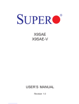
Motherboard Layout
Note: For the latest CPU/Memory updates, please refer to our website at
http://www.supermicro.com/products/motherboard/ for details.
BT1
JPCIE3
LEDPWR
I-SGPIO2
LE6
JBT1
BIOS
LICENSE
JPI2C1
JTBT1
J24
JPWR1
JPWR2
JF1
JD1
JHD_AC1
JSPDIF_OUT
JSPDIF_IN
J21
JL1
JSD1
JSD2
JSTBY1
JTPM1
JVRM2
JVRM1
JPAC1
JPL2
JPL1
JPUSB1
JBR1
JI2C2
JPME2
JI2C1
J23
SP1
FAN3
FANA
FAN6
FAN4
FAN2
FAN1
MAC CODE
X10DAL-i
BAR CODE
AUDIO FP
HD AUDIO
(3.0)
USB5/6
(3.0)
USB7/8(3.0)
USB1/2
USB0
USB3/4
S-SATA2
S-SATA0
S-SATA1
S-SATA3
I-SATA5
CPU1 SLOT1 PCI-E 3.0 X8 (IN X16)
I-SATA4
CPU2 SLOT2 PCI-E 3.0 X4 (IN X8)
I-SATA3
I-SATA2
I-SATA1
CPU1 SLOT3 PCI-E 3.0 X16
I-SATA0
CPU1 SLOT5 PCI-E 3.0 X16
P2-DIMME1
P1-DIMMC1
P2-DIMMF1
P1-DIMMD1
P2-DIMMH1
P1-DIMMB1
P1-DIMMA1
LAN2
P2-DIMMG1
LAN1
COM1
I-SGPIO1
S-SGPIO
PCH SLOT6 PCI-E 2.0 X4 (IN X8)
JWD1
Rev. 1.02
1
FAN5
CPU1
CPU2
Battery
PCH
BIOS

1-4
X10DAL-i Motherboard User's Manual
Notes:
•See Chapter 2 for detailed information on jumpers, I/O ports and JF1 front
panel connections.
•" " indicates the location of "Pin 1".
•Jumpers/LEDs not indicated are for testing only. Also, components that are not
documented in this manual are reserved for internal use only.
•Use only the correct type of onboard CMOS battery as specied by the manu-
facturer. Do not install the onboard battery upside down to avoid damaging the
motherboard.
X10DAL-i Quick Reference
BT1
JPCIE3
LEDPWR
I-SGPIO2
LE6
JBT1
BIOS
LICENSE
JPI2C1
JTBT1
J24
JPWR1
JPWR2
JF1
JD1
JHD_AC1
JSPDIF_OUT
JSPDIF_IN
J21
JL1
JSD1
JSD2
JSTBY1
JTPM1
JVRM2
JVRM1
JPAC1
JPL2
JPL1
JPUSB1
JBR1
JI2C2
JPME2
JI2C1
J23
SP1
FAN3
FANA
FAN6
FAN4
FAN2
FAN1
MAC CODE
X10DAL-i
BAR CODE
AUDIO FP
HD AUDIO
(3.0)
USB5/6
(3.0)
USB7/8(3.0)
USB1/2
USB0
USB3/4
S-SATA2
S-SATA0
S-SATA1
S-SATA3
I-SATA5
CPU1 SLOT1 PCI-E 3.0 X8 (IN X16)
I-SATA4
CPU2 SLOT2 PCI-E 3.0 X4 (IN X8)
I-SATA3
I-SATA2
I-SATA1
CPU1 SLOT3 PCI-E 3.0 X16
I-SATA0
CPU1 SLOT5 PCI-E 3.0 X16
P2-DIMME1
P1-DIMMC1
P2-DIMMF1
P1-DIMMD1
P2-DIMMH1
P1-DIMMB1
P1-DIMMA1
LAN2
P2-DIMMG1
LAN1
COM1
I-SGPIO1
S-SGPIO
PCH SLOT6 PCI-E 2.0 X4 (IN X8)
JWD1
Rev. 1.02
1
FAN5
CPU1
CPU2
Battery
PCH
BIOS

Chapter 1: Overview
1-5
JPME1 ME Recovery Pins 2-3 (Normal)
X10DAL-i Jumpers
Jumper Description Default Setting
JBT1 Clear CMOS See Chapter 2
JI
I2
C1/JI
I2
C2 SMBus to PCI-E slots Pins 2-3 (Disabled)
JPAC1 Audio enable Pins 1-2 (Enabled)
JPL1 GLAN1 Enable/Disable Pins 1-2 (Enabled)
JPL2 GLAN2 Enable/Disable Pins 1-2 (Enabled)
JPME2 ME (Manufacture) Mode Select Pins 1-2 (Normal)
JPUSB1 USB 0/1 Wake-up Enable Pins 1-2 (Enabled)
JWD1 Watch Dog Pins 1-2 (Reset)
J21 LAN controller EEPROM update Open (Disabled)
X10DAL-i Connectors
Connectors Description
Audio_FP Audio connector for front access
HD Audio 5.1 HD (6-channel High-Denition) + SPDIF audio connector
BT1 Onboard CMOS battery (See Chapter 3 for used battery disposal)
COM1 Serial port header
CPU1 Slot1 PCI-E 3.0 x 8 in 16 slot
CPU2 Slot2 PCI-E 3.0 x 4 in 8 slot (This slot is available when CPU2 is installed.)
CPU1 Slot3/Slot5 PCI-E 3.0 x16 slots
PCH Slot6 PCI-E 2.0 x4 in x8 slot (See the note below for Thunderbolt AOC sup-
port.)
FAN1-6, FANA CPU/System fan headers
J24 ATX 24-pin power connector
JD1 Speaker/Power LED indicator
JF1 Front panel control header
JL1 Chassis intrusion header
JPI2C1 Power supply SMBbus I
2
C header
JPWR1/JPWR2 12V 8-Pin power connectors
JSD1/JSD2 SATA DOM (Device_On_Module) power connection headers 1/2
JSPDIF_In SPDIF_(Sony/Philips Digital Interface)_In header
JSPDIF_Out SPDIF_(Sony/Philips Digital Interface)_Out header
Note: This motherboard supports the latest Thunderbolt technology. For
proper Thunderbolt support, please install the Thunderbolt add-on card on
PCH Slot6 and connect the GPIO cable from the Thunderbolt add-on card
to the GPIO header (JTBT1) on the motherboard for TBT hot-plug support.
JBR1 BIOS Recovery Pins 2-3 (Normal)

1-6
X10DAL-i Motherboard User's Manual
Warning: To prevent damage to the power supply or motherboard, please use a power
supply that contains a 24-pin and two 8-pin power connectors. Be sure to connect
these power supply connectors to the 24-pin power connector (J24) and two 8-pin
power connectors (JPWR1, JPWR2) on the motherboard. Failure in doing so will void
the manufacturer warranty on your power supply and motherboard.
JSTBY1 Standby power header
JTBT1 GPIO (General-Purpose I/O) header for Thunderbolt add-on card (See
the note on page 1-5 for Thunderbolt AOC support.)
JTPM1 TPM (Trusted Platform Module)/Port 80 header
LAN1/LAN2 Gigabit Ethernet ports 1/2
I-SATA0-5 Serial_Link ATA (SATA 3.0) connections 0-5 supported by Intel PCH
(I-SATA4/5 support Supermicro SuperDOMs [Devices-on-Module] with
power pins built-in)
S-SATA 0-3 Serial_Link ATA (SATA 3.0) connections 0-3 supported by Intel SCU
SP1 Onboard buzzer (internal speaker)
I-SGPIO 1/2, S-SGPIO Serial_Link General_Purpose IO (SGPIO) headers (I-SGPIO 1: I-SA-
TA0-3, I-SGPIO 2: I-SATA4/5, S-GPIO: S-SATA0-3)
USB 3/4 (3.0) Rear USB 3.0 ports 3/4 on the IO backpanel
USB 1/2 (2.0) Front USB 2.0 ports 1/2 for front access
USB 5/6 (3.0) Rear USB 3.0 ports 5/6 on the IO backpanel
USB 7/8 (3.0) Front-accessible USB 3.0 connections 7/8
USB 0 (2.0) Type A USB 2.0 USB connection header
X10DAL-i LED Indicators
LED Description State
LEDPWR Power LED Solid On: Power On, Blinking: Suspend to RAM

Chapter 1: Overview
1-7
Motherboard Features
CPU
• Dual Intel
®
E5-2600v3 Series Processors (Socket R
LGA 2011); each processor supports two full-width
Intel QuickPath Interconnect (QPI) links (with support
of up to 9.6 GT/s per QPI link).
Memory
• Integrated memory controller supports up to 512 GB
of Load Reduced (LRDIMM) or 256 GB Registered
(RDIMM) ECC DDR4 2133/1866/1600 MHz memory
modules in 8 DIMM slots.
Note 1: Memory speed support is dependent on
the CPUs installed on the motherboard.
Note 2: For the latest memory updates, please
refer to the Tested Memory List posted on our
website (http://www.supermicro.com/products/
motherboard).
• Virtualization: VT-x, VT-d, and VT-c
Chipset
• Intel® C612 Chipset (PCH)
Expansion
• Two (2) PCI-Express 3.0 x16 slots (CPU1 Slot3,
CPU1 Slot5),
• One (1) PCI-Express 3.0 x8 in x16 slot (CPU1 Slot1),
• One (1) PCI-Express 3.0 x4 in x8 slot (CPU2 Slot2),
• One (1) PCI-Express 2.0x4 in x8 slot (PCH Slot6)
(See the note on Page 1-5.)
Slots
Network
• Two (2) i210 Gigabit (100/1000 Mb/s) Ethernet con-
trollers for LAN 1/LAN 2 ports.
SATA/SAS Connections
• SATA Ports • Six (6) SATA 3.0 ports sup-
ported by Intel PCH (I-SATA
0-5)
Note: I-SATA4/5 sup-
port Supermicro Su-
perDOMs [Devices-
on-Module] with power
pins built-in)
• Four (4) SATA 3.0 ports
supported by Intel SCU
(S-SATA 0-3)
• RAID RAID 0, 1, 5, 10

1-8
X10DAL-i Motherboard User's Manual
Peripheral
Devices
USB Devices
• Four (4) USB 3.0 connections on the IO backpanel
(USB 3/4, 5/6)
• Two (2) USB 3.0 connections for front access (USB
7/8)
• Two (2) USB 2.0 connections for front access (USB
1/2)
• One (1) Type A USB 2.0 header (USB 0)
I/O Devices
Audio
• ALC888S Audio controller
• Rear 5.1 High-Denition + SPDIF audio (HD Audio)
(Note: 7.1 can be supported via SPDIF)
• Audio header for front access (Audio_FP)
• SPDIF_In/SPDIF_Out (Sony_Philips Digital Inter-
face)_In/Out headers
Power Con-
nectors
System Power Connectors
• One (1) 24-pin Main power (J24)
• Two (2) 8-pin CPU power connectors (JPWR1/2)
Super IO
Super IO
• NCT 7904
BIOS
• 16MB AMI SPI BIOS
®
• DMI 2.3, PCI 2.3, ACPI 1.0/2.0/3.0, Plug & Play
(PnP) and SMBIOS 2.3
Thunderbolt Technology Support
• Intel Thunderbolt Technology supported
Note: This motherboard supports the latest
Thunderbolt technology. For proper Thunder-
bolt support, please install the Thunderbolt
add-on card on PCH Slot6 and connect the
GPIO cable from the Thunderbolt add-on card
to the GPIO header (JTBT1) on the mother-
board for Thunderbolt hot-plug support.
Power
• ACPI/APM Power Management
• Main switch override mechanism
• Keyboard Wake-up from Soft-Off USB
• Power-on mode for AC power recovery
Cong.

Chapter 1: Overview
1-9
System-
Health
CPU Monitoring
Monitoring
• Onboard voltage monitors for 1.05V, 1.25V, 1.5V,
+3.3V, 3.3VSB, +5V, +5V Standby, +12V, chipset,
memory, CPU1/2 vcores, and battery voltages.
• CPU/System overheat LED and control
• CPU Thermal Trip support
• Thermal Monitor 2 (TM2) support
Fan Control
• Low noise fan speed control
LED Indicators
• System/CPU Overheat LED
• Suspend-state LED
System
Management
System Management
• PECI (Platform Environment Conguration Interface)
2.0 support
• System resource alert via SuperDoctor® 5
• Thermal Monitor 2 (TM2) support
• Chassis Intrusion Header and Detection
• SuperDoctor® 5, Watch Dog, NMI
Dimensions
• 12.00" (L) x 10.00" (W) (304.80 mm x 254.00 mm)
Note: Both CPUs need to be installed for full access to the PCI-E slots,
DIMM slots, and onboard controllers. Refer to the block diagram on page
1-10 to determine which slots or devices may be affected.

1-10
X10DAL-i Motherboard User's Manual
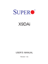
System Block Diagram
Note 1: This is a general block diagram and may not exactly represent
the features on your motherboard. See the Motherboard Features pages
for the actual specications of each motherboard.
Note 2: This block diagram is intended for your reference only.
Note 3: Both CPUs need to be installed for full access to the PCI-E slots,
DIMM slots, and onboard controllers. Refer to the block diagram above to
determine which slots or devices may be affected.
Debug Card
Block Diagram Rev. 1.02
X10DAL-i
#5/6/7/8
PCH
USB
TPM HEADER
BIOS
HEADER
#1
SLOT 5
5 PHASE
160W
P2
P2
P1
VR12.5
P1
#1-4
#1-3
#1-2
SLOT 3
PCI-E X16
2
SNB CORE
DDR4
SNB CORE
DDR4
5 PHASE
160W
VR12.5
PCI-E X16
#3
#2-3
#2-4
TDP:6.5W (WORKSTATION)
5W (SERVER)
USB & SATA useage different
Idle:0.45W
5V:1.2A
3.3V:0.1A
3.3 STBY:0.2A
1.05 PCH
1.05 ASW
1.5 PCH
PVCCIO 1.0/0.95
LAN2
I210
LAN1
#2
#3
#4
PCI-E X8
SLOT 2
#2D
I210
SLOT 6
PCI-E X4 in X8
RJ45
RJ45
SLOT 1
PCI-E X8 in X16
#1
#0
#5
#4
#3
#2
#6
#7
#8
#9
Super I/O
NCT6776
COM
AUDIO
ALC888S
Audio
Ports
SATA
#2-2
1866/2133
#2-1
DDR4
1866/2133
DDR4
#1-1
USB
CPU1
CPU2
#2
#1
DMI
#1 #2A
#3
2
DMI
QPI
9.6G
QPI
9.6G
PCI-E x16 G3
PCI-E x16 G3
PCI-E x8 G3
PCI-E x4 G2
LPC
SPI
USB 2.0
USB 3.0
SATA 3.0
x2 in Header
x1 in Type A
x2 in Header
x4 in Rear I/O
2
DMI
4GB/s
PCI-E x4 G3

Chapter 1: Overview
1-11
1-2 Processor and Chipset Overview
Built upon the functionality and the capability of the Intel E5-2600v3 Series proces-
sors (Socket R v3 LGA 2011) and the C612 chipset, the X10DAL-i motherboard
provides the performance and feature sets required for small-form factor worksta-
tion platforms, optimized for medical imaging applications.
With support of Intel QuickPath interconnect (QPI) Technology, the X10DAL-i of-
fers point-to-point serial interconnect interface with a transfer speed of up to 9.6
GT/s, providing superb system performance.
The C612 chipset provides extensive IO support, including the following features:
•DDR4 288-pin memory support
•Support for MCTP protocol and ME
•GSX capable of GPIO expansion
•Improved I/O capabilities to high-storage-capacity congurations
•SPI Enhancements
•Intel® Node Manager 3.0
Note: Node Manager 3.0 support is dependent on the power supply used
in the system.
/