Page is loading ...

STRIP NAILER
NR 65AK
LIST No. 1099 Sep. 2001
POWER TOOLS
TECHNICAL DATA
AND
SERVICE MANUAL
SPECIFICATIONS AND PARTS ARE SUBJECT TO CHANGE FOR IMPROVEMENT
N
MODEL
NR 65AK

Notice for use
Specifications and parts are subject to change for improvement.
Refer to Hitachi Power Tool Technical News for further information.

REMARK:
Throughout this TECHNICAL DATA AND SERVICE MANUAL, a symbol(s)
is(are) used in the place of company name(s) and model name(s) of our
competitor(s). The symbol(s) utilized here is(are) as follows:
Symbols Utilized
Competitors
Company Name
Model Name
PASLODE
5250/65SPP
Y
SENCO
SN60MC
R

Page
CONTENTS
1. PRODUCT NAME..................................................................................................................1
2. MARKETING OBJECTIVE ....................................................................................................1
3. APPLICATIONS .....................................................................................................................1
4. SELLING POINTS .................................................................................................................1
5. SPECIFICATIONS .................................................................................................................2
5-1. Specifications........................................................................................................................ 2
5-2. Nail Selection ........................................................................................................................ 3
5-3. Nail Driving Force ................................................................................................................. 4
6. COMPARISONS WITH SIMILAR PRODUCTS .....................................................................5
7. PRECAUTIONS IN SALES PROMOTION ............................................................................6
7-1. Instruction Manual ............................................................................................................... 6
7-2. Warning Label ....................................................................................................................... 6
7-3. Related Laws and Regulations ............................................................................................. 7
8. MECHANISM AND OPERATION PRINCIPLE ......................................................................7
8-1. Mechanism ........................................................................................................................... 7
8-2. New Mechanism ................................................................................................................. 10
8-3. Operation Principle ............................................................................................................. 14
9. TROUBLESHOOTING GUIDE ............................................................................................16
9-1. Troubleshooting and Correction.......................................................................................... 16
9-2. Possible Causes and Corrections of Air Leakage............................................................... 20
10. DISASSEMBLY AND REASSEMBLY ...............................................................................22
10-1. General Precautions in Disassembly and Reassembly .................................................... 22
10-2. Disassembly and Reassembly of the Output Section ....................................................... 23
10-3. Disassembly and Reassembly of the Control Valve Section ............................................ 25
10-4. Disassembly and Reassembly of the Driving Section ...................................................... 28
10-5. Disassembly and Reassembly of the Cap and the Magazine Section ............................. 31
11. INSPECTION AND CONFIRMATION AFTER REASSEMBLY .........................................36
12. STANDARD REPAIR TIME (UNIT) SCHEDULES ............................................................37
Assembly Diagram for NR 65AK

--- 1 ---
1. PRODUCT NAME
Hitachi 2-1/2" Strip Nailer, Model NR 65AK
2. MARKETING OBJECTIVE
There is an increasing demand for the metal hardware used for framing work to resist earthquakes and
hurricanes. Although competitors have already put their nailers specifically designed for the metal hardware, they
do not meet the market requirements sufficiently because they are reputed as "low strength", "trouble-prone",
and "large and heavy". The new Model NR 65AK strip nailer clears the above problems and features the
following:
1. Compact and lightweight (2.9 kg)
2. New-type pushing lever is adopted:
(1) Easy to aim at the desired nailing position
(2) No need of lever shifting operation
(3) High strength
3. Easy to drive nails at corners thanks to the short center height
4. Easy to adjust nail lengths
The new nails specifically designed for the Model NR 65AK are also provided (refer to page 3). The Model NR
65AK has already been registered under the trade name of "STRAP TITE" as a strip nailer specifically designed
for the metal hardware.
3. APPLICATIONS
Metal hardware with pre-punched holes to wood stud installation only (straps, joint hangers, framing anchors).
4. SELLING POINTS
Exhaust direction easily
changeable
Aluminum magazine
Racket grip for comfort and
temperature protection
Lightweight 2.9 kg (6.4 lbs.) for easy one-handed operation
38 mm
(1-1/2")
Short center height
Nail gate is easily
adjustable to the nail
lengths.
Well-balanced design locating
its center of gravity at the handle
Easy to aim at the desired
nailing position
No need of lever shifting
operation
High strength
New-type pushing lever

--- 2 ---
Optional accessories
Nail capacity
2.9 kg (6.4 lbs.)
1.8 ltr/cycle at 6.9 bar (1.8 ltr/cycle at 7 kgf/cm
2
) (0.063 ft
3
/cycle at 100 psi)
Corrugated cardboard box
2 nails/sec.
Driving speed
448 mm x 335 mm x 85 mm
(17-5/8" x 13-3/16" x 3-3/8")
44 nails (2 strips)
Dimensions
(Length x Height x Width)
Nail feed system
3/8 NPT thread
Standard accessories
Weight
Spiral spring
Air consumption
Air inlet
Package dimensions
(Length x Height x Width)
Packaging
476 mm x 383 mm x 132 mm
(18-3/4" x 15" x 5-7/32")
Eye protector (Code No. 875769)
..............................................................
1
Hex. bar wrench for M5 screw (Code No. 944459)
....................................
1
Hex. bar wrench for M4 screw (Code No. 944458)
....................................
1
Hex. bar wrench for M3 screw (Code No. 943277)
....................................
1
Pneumatic tool lubricant (1 oz oil feeder) (Code No. 877153)
Pneumatic tool lubricant (4 oz oil feeder) (Code No. 872042)
Pneumatic tool lubricant (1 quart can) (Code No. 876212)
5. SPECIFICATIONS
5-1. Specifications
Reciprocating piston type
Model
Driving system
NR 65AK
Operating pressure
5.4 --- 8.3 bar (5.5 --- 8.5 kgf/cm
2
, 80 --- 120 psi) (Gauge pressure)

--- 3 ---
5-2. Nail Selection
The Model NR 65AK utilizes heat treated round-head nails collated with paper into bands of 22 pieces.
Applicable nail dimensions are shown below. However, it is recommended to use genuine HITACHI nails to
ensure satisfactory driving quality.
WARNING
Use only genuine HITACHI heat treated nails for this NR 65AK to avoid serious injury from ricocheting
nails. The use of any other nails and non-heat treated nails could result in dangerous tool malfunction
and/or nail malfunction, causing serious injury.
Select adequate nail size to meet proper metal hardware requirement needed for application, designed
by metal hardware manufacturer and regulated by the applicable building code.
CAUTION: Ensure that nails are as specified in Fig. 1. Other nails will cause jamming of nails and
subsequent damage to the nailer.
280"
(7.1 mm)
1-1/2" (38 mm)
Min.
Fig. 1 Dimensions of nails
Max.
280"
(7.1 mm)
2-1/2" (64 mm)
.162"
(4.1 mm)
(8d) .131 x 1-1/2" (3.3 x 38 mm)
(10d) .148 x 1-1/2" (3.8 x 38 mm)
(10d) .148 x 2-1/2" (3.8 x 64 mm)
(16d) .162 x 2-1/2" (4.1 x 64 mm)
Paper-collated strip nails
Full-head nails
.131"
(3.3 mm)

--- 4 ---
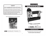
5-3. Nail Driving Force
Fig. 2 shows by type of wood and nail the nailer output energy provided by the supply pressure and the nailing
energy required for driving the nail flush. Air pressure which exceeds the intersecting point between the nailer
output energy and the required nailing energy for driving the nail allows the nail to be fully driven.
For example, when driving a nail of 3.3 mm dia. x 38 mm length (0.131" x 1-1/2") into a workpiece of hemlock with
the Model NR 65AK, a pressure of about 5.5 bar (5.7 kgf/cm
2
, 80 psi) allows the nailer to drive the nail flush with
the wood surface. A pressure beyond this value causes the nail head to be driven below the wood surface.
Fig. 2 should be used as a reference only because those values vary depending on the type of wood, moisture
content, and grain of wood.
Fig. 2 Required nailing energy and nailer output energy
Air pressure setting to drive nail flush with NR 65AK
Hemlock
HITACHI NR 65AK
Y
R
3.3 x 38 mm (0.131" x 1-1/2")
3.8 x 38 mm (0.148" x 1-1/2")
3.8 x 64 mm (0.148" x 2-1/2")
4.1 x 64 mm (0.162" x 2-1/2")
200 250100 150
(mm
2
)
0.15
0.2
0.25
0.3 0.35 0.4
(in
2
)
80
60
40
20
1000
800
600
400
200
100
80
60
40
20
80
60
40
20
1000
800
600
400
200
100
80
60
40
20
Required nailing energy Nailer output energy

--- 5 ---
7.8 mm
2.6 mm
(.1")
Handle grip
Shank dia.
Applicable
nails
Head dia.
Collation
Length
38 mm -- 64 mm
(1-1/2" -- 2-1/2")
Racket grip
(Comfortable grip)
Paper
7.1 mm (.28")
3.3 mm -- 4.1 mm
(.131" -- .162")
Rubber
(Not elastic)
Paper
3.3 mm -- 4.1 mm
(.131" -- .162")
Rubber
(Not elastic)
Paper
7.1 mm (.28")
3.3 mm -- 4.1 mm
(.131" -- .162")
38 mm -- 64 mm
(1-1/2" -- 2-1/2")
7.1 mm (.28")
38 mm -- 64 mm
(1-1/2" -- 2-1/2")
6. COMPARISONS WITH SIMILAR PRODUCTS
Maker
HITACHI
Air consumption at 6.9
bar (7 kgf/cm
2
, 100 psi)
Operating pressure
Center height
Direction change of
exhaust air
Magazine type
(Material)
Tool-less
(360 deg)
Weight
Dimensions
(L x H x W)
Method of locate
Change nail length
The center of gravity
5.4 --- 8.3 bar
(5.5 --- 8.5 kgf/cm
2
)
(80 --- 120 psi)
448 mm x 335 mm x 85 mm
(17-5/8" x 13-3/16" x 3-3/8")
Model name
NR 65AK
1.8 ltr/cycle
(0.63 ft
3
/cycle)
44 nails
(2 strips)
Rear loading
(Aluminum)
Nail capacity
Nail point
2.9 kg (6.4 lbs.)
Adjust the nail gate
Located at the
handle for good
balance (Fig. 3)
38 mm
(1-1/2")
465 mm x 346 mm x 114 mm
(18-5/16" x 13-5/8" x 4-1/2")
365 mm x 330 mm x 111 mm
(14-1/2" x 13" x 4-3/8")
5.4 --- 8.3 bar
(5.5 --- 8.5 kgf/cm
2
)
(80 --- 120 psi)
5.4 --- 8.3 bar
(5.5 --- 8.5 kgf/cm
2
)
(80 --- 120 psi)
2.5 ltr/cycle
(0.88 ft
3
/cycle)
2.2 ltr/cycle
(0.77 ft
3
/cycle)
Top loading
(Plastic)
Rear loading
(Aluminum)
None
None
Probe
Nail point
Turn the lever
(Fig. 4)
Change position of
the nail rail
(Fig. 5)
4.1 kg (9 lbs.) 3.6 kg (7.7 lbs.)
Fig.3
Driver blade shape
Center height
The center of gravity
10.8 mm
(.42")
7.8 mm
(.3")
5.8 mm
(.23")
(.3")
5.5 mm
(.21")
Fig.4
Probe
The lever
Fig.5
The nail rail
44 --- 48 nails
(2 strips)
30 nails
(1 strip)
60 mm
(2-3/8")
51 mm
(2")
YR
Nail gate

--- 6 ---
7. PRECAUTIONS IN SALES PROMOTION
In the interest of promoting the safest and most efficient use of the Model NR 65 AK Nailer by all of our customers,
it is very important that at the time of sale the salesperson carefully ensures that the buyer seriously recognizes
the importance of the contents of the Instruction Manual, and fully understands the meaning of the precautions
listed on the Warning Label attached to each tool.
7-1. Instruction Manual
Although every effort is made in each step of the design, manufacture, and inspection to provide protection
against safety hazards, the dangers inherent in the use of any pneumatic tool cannot be completely eliminated.
Accordingly, general precautions and suggestions for use of pneumatic tools, and specific precautions and
suggestions for the use of the pneumatic nailer are listed in the Instruction Manual to enhance the safe, efficient
use of the tool by the customer.
Salespersons must be thoroughly familiar with the contents of the Instruction Manual to be able to offer
appropriate guidance to the customers during sales promotion.
7-2. Warning Label
Each Model NR 65AK unit is provided with a Warning Label (illustrated below) which lists basic safety precautions
in its use. Carefully ensure that customers fully understand and follow these precautions before using the tool.

--- 7 ---
7-3. Related Laws and Regulations
As nailers and staplers are designed to instantaneously drive nails and staples, there is an ever-present danger of
misfiring and subsequent possible serious injury. Accordingly, close attention in handling is absolutely necessary
at all times. Carefully ensure that the customer is fully aware of the precautions listed in the Instruction Manual
provided with each unit.
While there are no specific safety regulations, there are related items in various general safety regulations with
which the salespersons should be familiar in order to properly advise the customer. Please check your national
and/or local regulations for applicable items. Some applicable items are outlined below.
The U.S.A:
OSHA 1926.102 Eye and face protection
1926.302 Power-operated hand tools
ANSI SNT-101-1993 Portable, Compressed-Air-Actuated,
Fastener Driving Tools-Safety Requirements for
8. MECHANISM AND OPERATION PRINCIPLE
8-1. Mechanism
As illustrated in Fig. 6, NR 65AK can be generally divided into four sections:
output section, control valve section, driving section and magazine section. Most of the parts of the above
sections except the control valve section have been newly designed for maximum performance in a strip nailer.
Features of the main parts are described below.
Output section
...................
Most of the parts have been newly designed, though its basic construction is the
same as that of the Model NV 45AC. The piston unit employs O-rings at the
sliding portion in the same manner as the Model NV 45AC instead of a piston
ring.
Control valve section
..........
This section is common to the Models NR 90AC and NV 65AH except for plunger
spring (B).
Driving section
....................
All the parts have been newly designed. Especially, three pushing levers are
its own characteristics. The plastic guard shielding the pushing levers has been
newly designed to keep the pushing levers from contact with dust.
Magazine section
................
All the parts have been newly designed. The magazine made of aluminum forms
two nail head paths with the guide plate. The nail feeder made of plastic has
been newly designed.

--- 8 ---
This tool has a sequential trip mechanism (single shot) for use when precision nail placement is necessary.
You must first depress the nail point where you want to drive a nail and then pull the trigger. After the nail is
driven, completely release the trigger and lift the tool off the work surface.
This tool is not designed for contact trip operation (bounce fire), and not available for contact trip valve units.
And this tool has a new pushing lever (safety) mechanism, this is a different push lever mechanism from another
nailers. The position of the pushing lever when the nail feeder is pulled back is shown as below.
When nails are loaded and the trigger is depressed, the pushing lever comes down and when the pushing lever
touches the workpiece, a nail is driven.
Nose
At firing
Pushing lever
Nose
Pushing lever
Pushing lever
At non-firing
Nose
Workpiece

--- 9 ---
Output section
Fig. 6 Construction
Top Cover [3]
Accumulator
Piston (H) [17]
(Driver blade)
Control valve section
Head Valve
(A) [10]
Exhaust Vent
Cylinder [15]
Piston
Bumper [19]
Nose [20]
Guard [23]
Pushing
Lever (A) [30]
Control valve section
Plunger Spring (B) [46]
Plunger (A) [47]
Valve Bushing (A) [49]
Valve Bushing (B) [40]
Valve Piston (B) [44]
Feeder Plate [81]
Nail Feeder [83]
Magazine Cover [71]
Magazine section
Body Ass'y [18]
Nail Gate [72]
Driving section
Pushing
Lever (B) [28]
Magazine [74]
O-Ring [16]
Cap [35]

--- 10 ---
Trigger [52]
Fig. 7
Fig. 8
8-2. New Mechanism
(1) Pushing lever mechanism
(a) The tip of Pushing Lever (A) [30] is at the back of
the nail point after loading nails in the Magazine
[74]. Thus, the nail point can be easily inserted
into the hole in the metal connector (Fig. 7).
Nail point
Pushing Lever (A)
[30]
Magazine [74]
Trigger [52]
Nail point
The hole
Workpiece
Metal connector
Plunger (A) [47]
Trigger
Arm [50]
(b) After inserting the nail point into the hole in the
metal connector, pull the Trigger [52] to make
the tip of Pushing Lever (A) [30] contact with
the surface of the metal connector. Then the
Trigger Arm [50] pushes up Plunger (A) [47]
and the nailer is started to drive nails (Fig. 8).

--- 11 ---
Fig. 9
Fig. 10
Trigger [52]
Nail point
Pushing Lever (A)
[30]
Trigger Arm [50]
Hole
Plunger (A) [47]
(c) By pulling the Trigger [52] when there is no
workpiece near the nail point, the Trigger Arm
[50] pushes up Pushing Lever (C) [24] and at the
same time Pushing Levers (A) and (B) [30] and
[28] move. At this time, Pushing Lever (B) [28]
turns in the direction going far from Pushing
Lever (A) [30] through the guide groove of the
Nose [20]. Thus Pushing Lever (B) [28] comes
off the groove of Pushing Lever (A) [30] (Fig. 9).
Pushing
Lever (C)
[24]
Nose [20]
Pushing Lever (B) [28]
Pushing
Lever (B)
[28]
Pushing
Lever (A)
[30]
Pushing
Lever (C)
[24]
Groove of Pushing
Lever (A) [30]
Pushing Lever
(B) [28]
(d) Push up the tip of Pushing Lever (A) [30]. Then
only Pushing Lever (A) [30] moves while Pushing
Levers (B) and (C) [28] and [24] do not move.
Since Plunger (A) [47] is not pushed up, the nailer
does not start (Fig. 10).
Guide groove
Come off
Enlarged

--- 12 ---
(2) Lockout feature mechanism
This tool is equipped with a lockout feature that
prevents the tool from being activated when there
are 4 or less nails in the Magazine [74].
When the number of nails in the Magazine [74]
becomes five or less, the Pushing Lever Stopper
[80] moves the bent portion of Pushing Lever (C)
[24] downward. The status of Pushing Lever (C)
[24] at this time is shown in Fig. 10. Thus the nailer
does not start even if the Trigger [52] is pulled or the
pushing lever is pushed up.
(3) Nail gate mechanism
(a) When nails are loaded in the Magazine [74], the end of the Shaft [59] is inserted into the groove of the Nail
Gate [72] and the Nail Gate [72] cannot move. Therefore, only the nails whose lengths match the position of
the Nail Gate [72] can be loaded in the Magazine [74] (Fig. 12).
Trigger [52]
Nail Feeder [83]
Pushing Lever (C)
[24]
Magazine [74]
Pushing Lever
Stopper [80]
Bent portion
Fig. 11
Fig. 12
Groove of
Nail Gate
[72]
Nail Gate [72]
Shaft [59]
Magazine [74]
Nail Feeder [83]
Magazne Cover [71]

--- 13 ---
(b) When no nails are loaded in the Magazine [74]:
By removing all the nails from the Magazine [74], the Nail Feeder [83] pushes the end of the Shaft [59] toward
the Nose [20] and the end of the Shaft [59] comes off the groove of the Nail Gate [72]. Thus the Nail Gate
[72] can be moved (Fig. 13). Nails of different length can be loaded by moving the Nail Gate [72].
The following label that lists precautions in the use of the Nail Gate [72] is provided on the Magazine [74].
Ensure that the customers fully understand and follow these precautions before using the tool.
Groove of nail gate
Nail Gate [72] can be moved.
End of Shaft [59]
Nose [20]
Nail Feeder [83]
Shaft [59]
Magazine [74]
Fig. 13
Nail Gate [72]

--- 14 ---
Fig. 14
8-3. Operation Principle
(1) Before nailing: (Fig. 14 and Fig. 15)
1) When compressed air is fed to the main body,
it fills the accumulator ( ).
2) At the same time, the compressed air flows into
the valve piston lower chamber of the control
valve section and forces Valve Piston (B) [44]
upward. Also, the compressed air is fed through
the air supply vent and air passage to the head
valve chamber. As a result, the Head Valve
Spring [8] is pushed down together to seal
Head Valve (A) [10] and Cylinder [15].
(2) When nailing: (Fig. 14 and Fig. 15)
1) When Pushing Lever (A) [30] and Trigger [52]
are operated together and Plunger (A) [47] is
pushed upward, the compressed air in the valve
piston lower chamber is discharged from the
bottom of Plunger (A) [47]. As a result, the
compressed air in the accumulator ( ) pushes
down Valve Piston (B) [44], blocking the air
supply vent and opening the exhaust valve.
2) When the exhaust valve opens, the compressed
air in the head valve chamber is discharged into
the atmosphere through the air passage.
3) When the air pressure applied on the bottom
surface of Head Valve (A) [10] overcomes the
strength of the Head Valve Spring [8], Head
Valve (A) [10] is pushed upward. At this time,
Head Valve (A) [10] seals the Exhaust Cover [5],
blocking the passage to the exhaust vent.
4) When Head Valve (A) [10] goes up, the
compressed air in the accumulator flows rapidly
into the Cylinder [15], forcing Piston (H) [17]
downward to strike the nail. When Piston (H)
[17] passes the cylinder hole, the compressed air
flows into the return air chamber and is
accumulated there.
Fig. 15 Control valve section

--- 15 ---
(3) During return: (Fig. 16 and Fig. 17)
1) When either Pushing Lever (A) [30] or Trigger
[52] is released, Plunger (A) [47] goes down
and the compressed air in the accumulator
flows into the valve piston lower chamber.
2) As the air pressure in the valve piston lower
chamber increases to overcome the air
pressure applied on the upper portion of Valve
Piston (B) [44], Valve Piston (B) [44] is forced
upward. When this occurs, the exhaust valve is
closed and the air supply vent is opened.
3) When the air supply vent opens, the compressed
air in the accumulator ( ) passes through the
air passage and flows into the head valve
chamber to push down Head Valve (A) [10].
As a result, Head Valve (A) [10] and Cylinder
[15] are sealed and, at the same time, Head
Valve (A) [10] and Exhaust Cover [5] are
released to open the exhaust vent.
4) The compressed air at the upper portion of
Piston (H) [17] is discharged into the
atmosphere through the exhaust vent. In this
way, the air pressure at the upper portion of
Piston (H) [17] is reduced, and the greater
pressure of the air accumulated in the return air
chamber pushes Piston (H) [17] upward.
5) If the air pressure at the lower portion of Piston
(H) [17] is higher than that of the atmosphere
after Piston (H) [17] has fully returned, the
excess air pressure is discharged into the
atmosphere through the clearance between the
Piston Bumper [19] and the driver blade.
Fig. 16
Fig. 17 Control valve section

--- 16 ---
Remove the adhesive
fragments and apply oil to
the nail feeder, ribbon
spring, guide rail and the
nail rail.
<Driving section: nose,
pushing lever
>
Nail inlet groove of the nose
is abnormal (deformed,
burrs or damaged).
Adhesive fragments are in
the nail inlet groove.
Problem
Possible cause
( : Most-common cause)
Inspection method Remedy
9. TROUBLESHOOTING GUIDE
9-1. Troubleshooting and Correction
1) Nails cannot
be driven.
<Nails>
Magazine is not loaded with
specified genuine nails.
Magazine is loaded with
abnormal nails (bent nails,
large or small round-head
nails, abnormal collation,
etc.).
Nails or collating band
clogs.
Collating band is deformed
or torn.
<Magazine section>
Magazine is abnormal
(deformed or damaged).
Nail feeder is abnormal
(deformed or damaged).
Ribbon spring is abnormal
(deformed or damaged).
Guide plate is abnormal
(deformed, burrs, damaged
or fatigued).
Nail rail is abnormal
(deformed, burrs, damaged
or fatigued).
Adhesive fragments are on
the guide plate and the nail
rail or they need oil.
Check if the magazine is
normally loaded with
specified nails.
Check if the nail feeder
operates smoothly in the
magazine.
Check if nails (one strip)
move smoothly in the
magazine.
Use specified nails.
Remove the abnormal nails
and load the magazine with
normal nails.
Check if nails (one strip) are
fed smoothly into the nail
injection port of the nose.
Pushing lever
Check the operation of the
pushing lever.
Repair or replace the
defective parts.
Repair or replace the
defective part.
Remove the adhesive
fragments.
Correct or replace the parts.
/