(Continued on the next page )
EtherNet/IP Communication Converter
IMR02E06-E2
Thank you for purchasing this RKC product. In order to achieve maximum performance and
ensure proper operation of your new instrument, carefully read all the instructions in this
manual. Please place this manual in a convenient location for easy reference.
This manual describes the basic operation method of the COM-ML. For the installation, the
communication data, the detail handling procedures and various function settings, please
read if necessary the following separate manuals.
• COM-ML [For SRZ] Installation Manual (IMR02E05-E): Enclosed with COM-ML
• COM-ML [For SRZ] Communication Data List (IMR02E07-E): Enclosed with COM-ML
• COM-ML [For SRZ] Instruction Manual (IMR02E08-E): Separate
(Download or sold separately)
The above manuals can be downloaded from our website:
URL: http://www.rkcinst.com/english/manual_load.htm
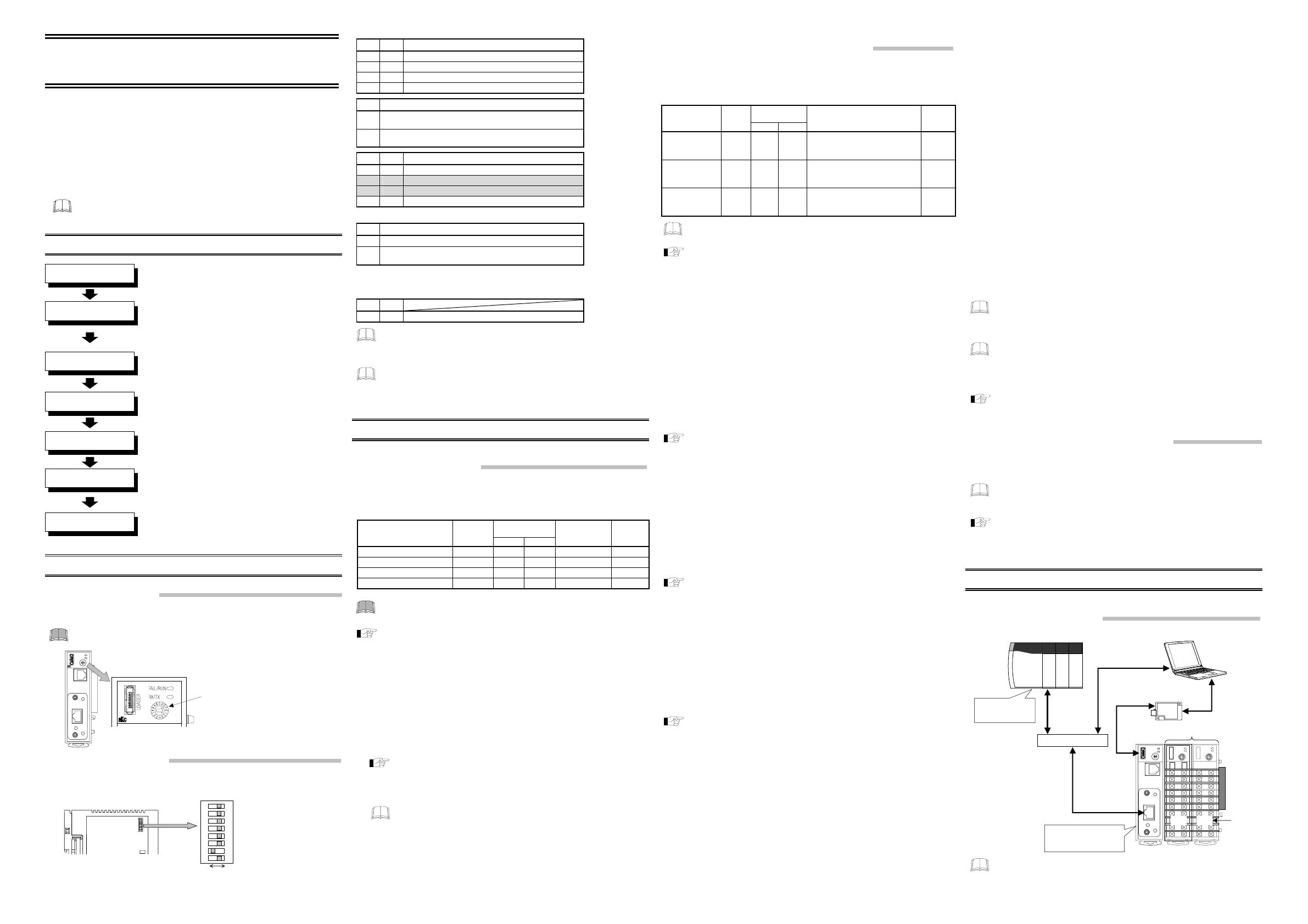
1. PROCEDURE FOR USING THE COM-ML
2. HOST COMMUNICATION SETTINGS
2.1 Address Settings
Set the address for host communication. Use a small flat-blade screwdriver to configure the
setting.
Set the address such that it is different to the other addresses on the same
line. Otherwise, problems or malfunction may result.
Host communication
address setting switch
Setting range:
0 to F [0 to 15: decimal numbers]
Factory set value: 0
COM-M
2.2 DIP Switch Settings
Use the DIP switch to set the speed and protocol of host communication, default IP address
setting, and DIP switch enable/disable.
Left side view
DIP switch
ON OFF
8 7 6 5 4 3 2
1
ON
1 2 Host communication speed
OFF OFF 4800 bps
ON OFF 9600 bps
OFF ON 19200 bps
ON ON 38400 bps
3 Communication protocol/Data bit configuration
OFF
RKC communication
(Data 8-bit, without parity, Stop 1-bit)
ON
Modbus
(Data 8-bit, without parity, Stop 1-bit)
6 7 Default IP address setting
OFF OFF Do not execute the default IP address setting
ON OFF Do not set this one
OFF ON Do not set this one
ON ON Execute the default IP address setting *
* See Default IP address setting (follows).
8 DIP switch enable/disable
OFF Enable (enable the DIP switch settings)
ON
Disable (enable the host communication or loader
communication settings)*
* The only host communication or loader communication settings that
are enabled are the host communication speed and protocol and the
data bit configuration.
4 5
OFF OFF Fixed
When the communication protocol is set with the DIP switch, the data bit
configuration is automatically set to “data 8-bit, without parity, stop 1-bit.” To
change to another data bit configuration, set the configuration in host
communication or loader communication.
If you wish to set the data bit configuration, host communication speed, and
communication protocol in host communication or loader communication, first set
DIP switch No. 8 to ON.
3. INITIAL COMMUNICATION DATA SETTINGS
Configure the initial communication data settings.
3.1 IP Address Settings
Set the IP address of the COM-ML.
The IP address can be set in host communication or loader communication.
Refer to the following RKC communication identifiers and Modbus register addresses to set
the IP address.
Modbus
register address
Name
RKC
identifier
HEX DEC
Data range
Factory
set value
First-byte of IP address QB 801B 32795 0 to 255 192
Second-byte of IP address QC 801C 32796 0 to 255 168
Third-byte of IP address QD 801D 32797 0 to 255 1
Fourth-byte of IP address QE 801E 32798 0 to 255 1
(Factory set value for COM-ML IP address: 192.168.1.1)
For the IP address, check with the administrator of the network (LAN) to
which the COM-ML is connected.
For information on connecting the COM-ML to a host computer, see COM-ML
[For SRZ ] Installation Manual (IMR02E05-E).
Default IP address setting
The IP address can be set to the factory set value using the DIP switches.
1. Turn off the power of COM-ML.
2. Turn on No. 6 and No. 7 of DIP switch.
3. Turn on the power of COM-ML.
4. The FAIL/RUN lamp will flash green for about 5 seconds and then light solidly.
At this point, the IP address changes to the factory set value “192.168.1.1” and the
DHCP selection will change to “0: DHCP is invalid.”
For DHCP selection, see COM-ML [For SRZ] Instrucation Manual
(IMR02E08-E).
5. Turn off the power of the COM-ML once again and return DIP switches No. 6 and No. 7
to OFF.
If DIP switches No. 6 and No. 7 are left ON, the set IP address will revert to
the factory set value every time the power is turned on.
6. Turn the power of the COM-ML back on. This completes the procedure.
3.2 EtherNet/IP Communication Settings
Configure settings necessary for EtherNet/IP communication.
In addition to host communication and loader communication, the settings can be used to
enable EtherNet/IP explicit message communication.
Items configured are “Communication data items setting,” “Number of measured data items
(IN),” and “Number of setting data items (OUT).”
Modbus
register address
Name
RKC
identifier
HEX DEC
Data range
(data size indicated in brackets [ ])
Factory
set value
Communication
data items setting
QG 8020
・
・
・
8051
32800
・
・
・
32849
RKC communication: 0 to 65535
Modbus: 0000H to FFFFH
[50]
65535
(FFFFH)
Number of
measured data
items (IN)
QH 8052
・
・
・
8083
32850
・
・
・
32899
0 to 128
0: Not used
[50]
0
Number of
setting data items
(OUT)
QI 8084
・
・
・
80B5
32900
・
・
・
32949
0 to 127
0: Not used
[50]
0
EtherNet/IP communication methods supported by the COM-ML are “I/O
Communication” and “Explicit Message Communication.”
For information on explicit message communication, see 4.4 Tool Settings and
4.6 Explicit Message Communication.
Communication data items setting
Set the object model “Controller communication data item setting object (0xC5: C5Hex)”
(hereafter called “0xC5”).
• 0xC5 attributes 100 to 149 (50 items) correspond to CH1 to CH50 of identifier QG of RKC
communication, and to Modbus register addresses 8020H to 8051H.
• In each item, set the Modbus register address (first address only) of all communication
items used in EtherNet/IP communication (I/O communication and explicit message
communication).
• Set items used in I/O communication (these can also be used in explicit message
communication) in attributes 100 and following without any intervals, and then set items
that are only used in explicit message communication.
• The data order in I/O communication is the same as the 0xC5 attribute order. Set the
number of data used in each item in 0xC6 and 0xC7.
• Set 65535 (FFFFH) in unused items. Communication items following attributes set to
65535 (FFFFH) are not used in I/O communication.
For object models and register addresses of communication items, see COM-ML
[For SRZ ] Communication Data List (IMR02E07-E) and COM-ML [For SRZ]
Instruction Manual (IMR02E08-E).
Number of measured data items (IN)
Set the object model “Controller communication measurement item setting object (0xC6:
C6Hex)” (hereafter called “0xC6”).
• In the attribute numbers of 0xC6 that are the same as the attribute numbers of the
communication items used in the measurement items (IN) of I/O communication (in the
communication items set in 0xC5), set the data size used.
• 0xC6 attributes 100 to 149 (50 items) correspond to CH1 to CH50 of identifier QH of RKC
communication and to Modbus register addresses 8052H to 8083H.
• Data up to a total of the set values in the attributes of 0xC6 (cumulative total from attribute
100) of 128 (0080H) are valid.
For object models, see COM-ML [ For SRZ] Communication Data List
(IMR02E07- E) and COM-ML [For SRZ] Instruction Manual (IMR02E08- E).
Number of setting data items (OUT)
Set the object model “Controller communication setting item (OUT) setting object (0xC7:
C7Hex)” (hereafter called “0xC7”).
• In the attribute numbers of 0xC7 that are the same as the attribute numbers of the
communication items used in the setting items (OUT) of I/O communication (in the
communication items set in 0xC5), set the data size used.
• 0xC7 attributes 100 to 149 (50 items) correspond to CH1 to CH50 of identifier QI of RKC
communication and to Modbus register addresses 8084H to 80B5H.
• Data up to a total of the set values in the attributes of 0xC7 (cumulative total from attribute
100) of 127 (007FH) are valid.
For object models, see COM-ML [ For SRZ] Communication Data List
(IMR02E07- E) and COM-ML [For SRZ] Instruction Manual (IMR02E08- E).
[Setting example]
Using CH1 to CH4 of the measured value (PV) and set value (SV) of the Z-TIO module in
I/O communication
Setting condition: Measured data items (IN): Measured value (PV), Set value (SV)
Setting data items (OUT): Set value (SV)
Assigned destination of communication item:
Measured value (PV): Attribute 100
Set value (SV): Attribute 101
RKC communication
• Communication item assignment (0xC5 setting)
Measured value (PV): Setting position: CH1 of identifier QG
Set value: 508 [First Modbus register address (DEC)]
Set value (SV): Setting position: CH2 of identifier QG
Set value: 2780 [First Modbus register address (DEC)]
• Number of measured data items (IN) (0xC6 setting)
Measured value (PV): Setting position: CH1 of identifier QH
Set value: 4 [For 4 channels]
Set value (SV): Setting position: CH2 of identifier QH
Set value: 4 [For 4 channels]
• Number of setting data items (OUT) (0xC7 setting)
Measured value (PV): Setting position: CH1 of identifier QI
Set value: 0 [Not used]
Set value (SV): Setting position: CH2 of identifier QI
Set value: 4 [For 4 channels]
Modbus
• Communication item assignment (0xC5 setting)
Measured value (PV): Setting position: 8020H
Set value: 01FCH [First Modbus register address (HEX)]
Set value (SV): Setting position: 8021H
Set value: 0ADCH [First Modbus register address (HEX)]
• Number of measured data items (IN) (0xC6 setting)
Measured value (PV): Setting position: 8052H
Set value: 0004H [For 4 channels]
Set value (SV): Setting position: 8053H
Set value: 0004H [For 4 channels]
• Number of setting data items (OUT) (0xC7 setting)
Measured value (PV): Setting position: 8084H
Set value: 0000H [Not used]
Set value (SV): Setting position: 8085H
Set value: 0004H [For 4 channels]
Set the data of CH1 to CH4 of the set value (SV) in the registers of each (RKC
communication: CH1 to CH4 of identifier S1; Modbus: 0ADCH to 0ACFH). The
data of the communication item set in each attribute of 0xC5 is also assigned to
the same attribute of the “controller object” (0x64: 64Hex).
I/O communication does the sending and receiving of the data with Assembly
object (0x04: 04Hex). Measured data items (IN) uses attribute 3 of instance 100,
and setting data items (OUT) uses attribute 3 of instance 101. The tool is used
in verification and setting of measured data items (IN) and setting data items
(OUT).
• For the I/O communication that used a tool, see 4.4 Tool Settings and 4.5 I/O
Communication.
•
For the method of accessing 0x64, see 4.6 Explicit Message Communication.
3.3 Other Communication Data Settings
Set communication data other than the items set in Section 3.2 (PID constants of the Z-TIO
and Z-DIO modules, event set values, etc.) using host communication, loader
communication, or explicit message communication of EtherNet/IP communication.
Host communication or loader communication is used to configure the IP address
setting, and thus it is possible to continue configuring EtherNet/IP communication
settings or other communication data settings after the IP address setting.
For each of the communication setting items, see COM-ML [ For SRZ]
Communication Data List (IMR02E07-E) and COM-ML [For SRZ] Instruction
Manual (IMR02E08-E).
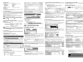
4. USAGE EXAMPLE
The example given in this section is based on the system configuration below.
4.1 System Configuration
EtherNet/IP
Programmable controller (PLC)
EtherNet/IP
communication converter
COM-ML
Rockwell Automation
ControlLogix 5555
Personal compute
SRZ
unit
Z-TIO module
Module
address
1 2
Loader
communication
(For initial settings)
USB communication
converter
COM-K
Network hub
EtherNet/IP
Ethernet
Loader communication is used for the initial communication data settings.
CO
ML
Quick Instruction
Manual
ll Rights Reserved, Copyright 2007, RKC INSTRUMENT INC.
Host communication
settings
Installation and wiring
IP address settings
EtherNet/IP
communication settings
See 2. HOST COMMUNICATION SETTINGS
• See COM-ML [For SRZ] Installation Manual
(IMR02E05-E)
• For information on the SRZ, see Z-TIO Instruction
Manual (IMS01T01-E) and Z-DIO Instruction Manual
(IMS01T03-E).
• See 3.2 EtherNet/IP Communication Settings
• See 4.4 Tool Settings
Factory set value:
19200 bps
Factory set value:
RKC
communication
[For SRZ]
Other communication
data settings
EtherNet/IP
communication
Controller (SRZ) settings
• See 4.2 Controller Settings
• See Z-TIO Host Communication Quick Instruction
Manual (IMS01T02-E) and Z-DIO Instruction Manual
(IMS01T03-E)
See 3.1 IP Address Settings
• See 3.3 Other Communication Data Settings
• See COM-ML [ For SRZ] Communication Data List
(IMR02E07- E) and COM-ML [For SRZ] Instruction
Manual (IMR02E08- E)
• See 4.5 I/O Communication
• See 4.6 Explicit Message Communication
Factory set value:
Enabled
Factory set value:
Do not execute
the default IP
address setting


 1
1
 2
2


RKC INSTRUMENT COM-ME-1 User manual
RKC INSTRUMENT COM-JL Installation guide
Allen-Bradley ControlLogix 1756-ENBT User manual
 Z-Com IMS01T05-E2 User manual
Mitsubishi Electric GOT2000 Series Connection Manual
Mitsubishi GOT2000Series Connection Manual
Micro Motion 5700 Integration Guide
Omron V680S to ControlLogix L71 User guide
Klein Tools 32794 Specification
